| PREV.: Counterbalance Applications of Multi-Function Valves | NEXT: Unloading Valves | Article Index | Home |
AMAZON multi-meters discounts AMAZON oscilloscope discounts There are three specific load conditions which make a simple counterbalance valve application undesirable. They are: over-center loads, varying loads, and press applications where maximum tonnage is required. However, by externally piloting the counterbalance valve from the opposite supply line to the actuator, the overcenter counterbalance valve im proves both system performance and efficiency. |
OVERCENTER LOADS
The term overcenter comes from the fact that, in many applications, the machinery’s geometry causes the load conditions to change from resistive to overrunning. This principle is represented in the example.
In the position shown, you can see that the load is resisting the extension of the cylinder. If a 3000 lbs. force is required at point A to move the load, and the cylinder has a piston area of one square inch, then 3000 PSI pressure is created in the fluid being supplied by the pump. At any pressure over 100 to 200 PSI, the overcenter counterbalance valve is piloted wide open, offering little resistance to flow from the rod end of the cylinder.
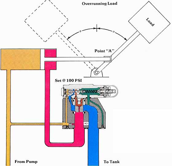
Above: (See
Color code legend for
above image)
After the load moves past the center line, the geometry of the load forces now pulls on the cylinder rod. When the load is at the same angle on the other side of center, a 3000 lb. load force is trying to extend the cylinder. Since the effective area on the rod end of the cylinder is slightly less than one square inch, a pressure slightly higher than 3000 PSI is needed to keep the load from free falling.
Because the overcenter type counterbalance is externally piloted, its opening and closing is not affected by pressure conditions in the rod end of the cylinder. It only responds to a pressure signal in its external pilot line, or, in this case, in the blind end of the cylinder.
When the load goes overcenter, the load forces try to pull the cylinder’s piston ahead of the oil supply from the pump. Under these conditions, there is no resistance to flow from the pump. In fact, the moment the piston gets ahead of the oil stream, a vacuum condition is created on the blind end of the cylinder.
We said earlier that, because of the pressure override characteristics of the multifunction valve, a change in pressure was necessary to fully open the valve. In our example, if the valve is set at 100 PSI cracking pressure, the full open position does not occur until a pilot pressure of 200 PSI is reached.
As the load moves overcenter, pressure is lost in the blind end of the cylinder. Consequently, a tendency for the closing of the counterbalance valve exists. The counterbalance valve resists the motion of the load with whatever pressure is necessary to maintain a 100 to 200 PSI pressure in the fluid being supplied by the pump.
You will notice that we have explained the operation of our overcenter counterbalance valve in only one direction of operation. For reverse motion of the load, a similar valve would have to be used on the blind end of the cylinder.
OVERCENTER VALVES WITH VARYING LOAD CONDITIONS
The major advantage of using an externally piloted over-center type counterbalance valve, with varying load, is that it greatly improves system efficiency. We said earlier, in our discussion of the simple counterbalance valve, that the pressure setting of the valve should be set slightly higher than the maximum load induced pressure. We also mentioned that any reduction in load meant that a higher pressure had to be supplied to the opposite end of the actuator to compensate for the loss in load induced pressure. In turn, this unnecessarily high pressure is converted into heat as flow is forced across the counterbalance.
When the externally piloted counterbalance is used, the valve becomes insensitive to the load induced pressure. The valve allows movement of the overhung load as long as a minimum pressure (approximately 100 PSI, depending on valve setting) is maintained in the opposite end of the actuator. You can see that, under these conditions, the hydraulic system never substantially adds to the heat generated in lowering the load, Of course, there is no way to prevent the potential energy of the load from being converted into heat, since the energy must be expelled as the load lowers. This must be taken into consideration when you are calculating the heat generated in the hydraulic system.
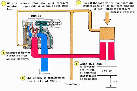
(See Color code legend for above image)
OVERCENTER VALVES ALLOW HIGHER PRESSING FORCE
The third major advantage of using a remotely piloted over- center type counterbalance valve is that full tonnage can be produced after the load has come into contact with a mechanical stop. Let us consider a down acting press with a relatively heavy upper platen.
In the example, as the platen moves through free air, its weight must be counterbalanced to prevent it from falling. If a simple internal pilot valve were to be used in this application, during the final pressing operation, the rod end of the piston would also be exposed to the pressure needed to counterbalance the weight of the platen during approach. This would be undesirable in this application, since the up acting counterbalancing force would, in effect, subtract the weight of the platen from the available pressing force. On the other hand, an externally piloted valve is wide open the moment pressure on the top of the cylinder’s piston exceeds the setting of the valve. This vents all pressure from the rod end of the cylinder. Under these conditions, the total pressing force available is calculated by adding the weight of the platen to the force due to system pressure over the top area of the piston.
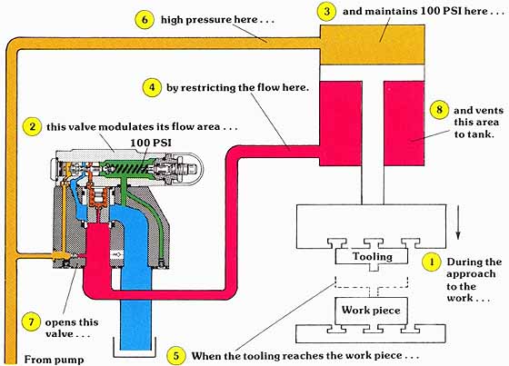
(See Color code legend for above image)
BRAKING WITH AN EXTERNALLY PILOTED COUNTERBALANCE VALVE
A problem sometimes arises when using an externally piloted counterbalance valve with fast moving, high inertia loads. If, for instance, we wanted to stop an inertia load in some mid position, the “x” port of the counterbalance would be vented when the directional control is centered. In losing pilot pressure, the counterbalance valve would slam closed, immediately stopping the motion of the load. If such a load, moving at a high speed, were to be brought to a stop quickly, damaging pressure peaks could develop in the service line between the actuator and the counterbalance valve. Therefore, in systems with high inertia loads, a port or crossport relief should be used in conjunction with the externally piloted counterbalance valve.
| Top of Page | PREV.: Counterbalance Applications of Multi-Function Valves | NEXT: Unloading Valves | Home |