| PREV.: Sequence Applications for Multi-Function Valves | NEXT: Overcenter Counterbalance Valves | Article Index | Home |
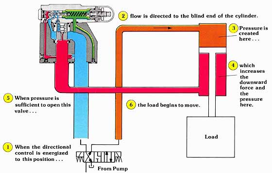
AMAZON multi-meters discounts AMAZON oscilloscope discounts Counterbalancing is an often-used term which actually covers several distinctly different valve applications. Unfortunately, this generality of meaning came about because all operations are related to the mass or inertia of the load rather than to the different valve applications. To aid in understanding this, we will discuss the individual applications and valve variation requirements. We will take a look at the different load conditions which determine whether the application is one of counterbalancing, overcenter, or braking. But first let us consider the simplest definition of counterbalancing. |
A counterbalance valve develops a pressure force in its actuator, which equally counteracts the force of the load. Counterbalancing is required whenever gravity can move the load faster than the speed intended by the hydraulic system. One criteria for the energy conscious designer is that the load conditions causing motion should always be the same. Let us now take a closer look at a simple counterbalance valve in application.
In this circuit, the basic counterbalance configuration of the multi-function valve is internally piloted and drained. In actuality, the valve is quite similar to a relief valve. The major difference is that a reverse free flow check valve is usually a necessity. The check valve permits a free flow of fluid towards the actuator in the reverse direction of operation.
Counterbalance valves can usually be internally drained, since the outlet of the valve is connected to tank through the directional valve whenever the valve is functioning. However, there is nothing preventing the use of the external drain in systems with high or fluctuating return line pressures.
In this example, when the directional control valve is centered, both the rod end of the cylinder, and the outlet of the multi-function valve, are connected to tank. It is important to choose a directional valve with this center configuration for two reasons.
The first reason is that directional controls shift in a small fraction of a second. If the valve were to block the outlet of the counterbalance valve rapidly, even if the counterbalance were to remain open, the oil coming from the rod end of the cylinder would have nowhere to go. This would eliminate the cushion stopping of the cylinder, which is one of the main ad vantages of a counterbalance valve in the first place. If we allowed the outlet of the counterbalance to be connected to tank when the directional control is centered, a cushioned stopping of the load would occur.
The second reason for using a directional control as shown is that it is important to preclude the possibility of a pressure build up on the top side of the cylinder. If the directional valve blocks all ports in center condition, high pressure from the pump could leak across the close tolerances of the spool and build on the blind end of the cylinder. As we will show, if the pressure builds high enough, the counterbalance valve will open, allowing the load to drift.
Above: (See
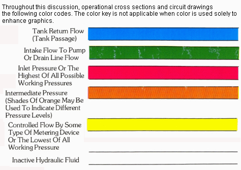
Color code legend for
above image)
For a better understanding, let us assign some arbitrary values to the previous circuits. Assume that the load is pulling on the cylinder rod with enough force to generate a pressure over the rod end area of the piston of 3000 PSI. Under these conditions, the counterbalance valve would be set slightly higher (3100 PSI) so that it would remain closed, supporting the load on a captured column of fluid.
At this point, it is important to note that although the load is supported by the counterbalance valves, it is not safe to assume that it is positively locked into position. Most industrial counterbalance valves are in some way related to a spool design. Leakage, although minimal, could allow the load to drift, especially if the load was held for extended time periods. As will be shown in a later section, the line contact sealing of a pilot operated check valve is the only way to assure positive holding of the load.
When the directional control is energized, pump flow is directed to the blind end of the cylinder. Since the piston can not move against the blocked column of fluid on its opposite side, a resistance to flow causes the pressure to rise on the top side of the piston. This increases the downward force, which in turn increases the pressure on the block column of fluid at the rod end of the cylinder. Assuming proper setting of the counterbalance, a minimal pressure on the top of the piston opens the valve, allowing downward movement of the load.
The pressure override characteristics of the multifunction valve allow it to open gradually over a 100 to 150 PSI pressure increase on the top side of the piston. Since pressure must be maintained in the blind end of the cylinder to keep the load in motion, the counterbalance modulates to pass just enough fluid to keep the cylinder from running away from the pump supply. The gradual opening and closing of the counterbalance valve causes smooth acceleration and deceleration of the load.
In our initial description of the counterbalance valve, we said that load conditions should be more or less constant. Any suspended weight has potential energy, or, better still, a potential for doing work. Ideally, since potential energy is available for doing the work, no additional energy should have to be supplied by the hydraulic system. In actual practice, however, we have shown that some energy is necessary to override the counterbalance. Of course, the closer the counterbalance is set to the actual load induced pressure, the more efficient the system becomes.
In our previous example, if we were to remove the load, all of the downward force would have to come from the hydraulic system. Assuming that we did not alter the setting of the counterbalance, all this hydraulic energy would be unnecessarily converted into heat as the pressurized fluid was forced over the counterbalance valve.
When punch pressure is equal to, or greater than, sequence valve setting, sufficient pilot pressure exists to hold the valve in the wide open position. Pressure in both the clamp and punch circuits equalizes at the higher pressure needed for the punching operation.

(See Color code legend for above image)
| Top of Page | PREV.: Sequence Applications for Multi-Function Valves | NEXT: Overcenter Counterbalance Valves | Home |