| PREV.: Pilot-Operated Multi-Function Valves | NEXT: Counterbalance Applications of Multi-Function Valves | Article Index | Home |
AMAZON multi-meters discounts AMAZON oscilloscope discounts The clamp and work circuit is the classical example of a sequence application. There is good reason for this, since there is no other method which solves this problem as simply. A pressure sequence valve assures a constant holding force in System I, while permitting System II to operate at any load induced pressure up to the pressure value of System I. If System II requires a higher pressure level than that needed to do the preliminary work in System I, the System will still perform satisfactorily up to the pressure level set on the main system relief. It is important to note, however, that when System II achieves a pressure level higher than that set on the sequence valve, System I will also be exposed to this higher pressure. If the work piece or machinery in System I could be damaged by this higher pressure, other precautions must be taken. These precautions could include sizing the actuators differently to obtain the desired force, or using a reducing valve in series with the System I actuator. |
The circuit shows a typical installation of a pressure sequence valve. A close look at the cross section will show you that most sequence valves are assembled with an internal pilot supply, but that they must always have an external drain. Upon actuation of the advance solenoid, the circuit automatically functions as follows:
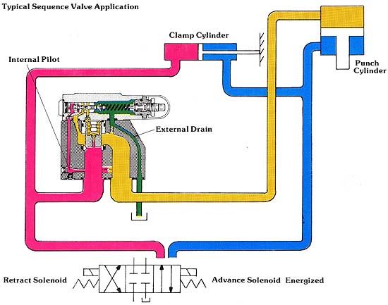
Above: Typical Sequence Valve Application. (See
Color code legend for
above image)
When the advance solenoid is energized, pump flow is directed to the blind end of the clamp cylinder, and to the inlet port of the sequence valve. Initially, the pressure in the line supplying the clamping cylinder is not high enough to open the sequence valve; hence, the full pump flow is available for cylinder extension. Upon reaching the work piece, the clamp cylinder stalls. Since the oil being supplied has nowhere to go, the pressure rises to the level which opens the sequence valve. The oil is then directed to the blind end of the punch cylinder.
During extension of the punch, there is little or no resistance to flow, as the punch is traveling through free air. Without the sequence valve in the circuit, the tendency would be for the pressure to equalize in both the clamp and the punch circuit, at the pressure level needed to extend the punch.
The sequence valve, however, will not allow this equalization of pressure to occur. The moment too much flow is allowed to enter the punch circuit, pressure drops slightly in the clamping circuit. This drop in pressure results in a relaxation of force holding the pilot spool in the original wide open position. The main poppet closes against the flow stream until an orifice is created which will pass the full output of the pump at a pressure drop sufficient to maintain clamping pressure at valve setting.
When the punch reaches the work piece, pressure rises to whatever level is necessary to pierce the material. This pressure can be less than, equal to, or greater than the minimum pressure required for the clamp circuit.
If the punch operates at any pressure lower than that required for the clamping circuit, the sequence valve modulates its orifice to maintain its inlet pressure at valve setting. At the same time, as load induced pressure increases in the punch circuit, the pressure drop across its main con trol spool decreases. Since the flow across an orifice is related to pressure drop, the sequence valve progressively moves its main poppet to a more open position, so that it can pass the full output flow of the pump.
When punch pressure is equal to, or greater than, sequence valve setting, sufficient pilot pressure exists to hold the valve in the wide open position. Pressure in both the clamp and punch circuits equalizes at the higher pressure needed for the punching operation.
(See Color code legend for above image)
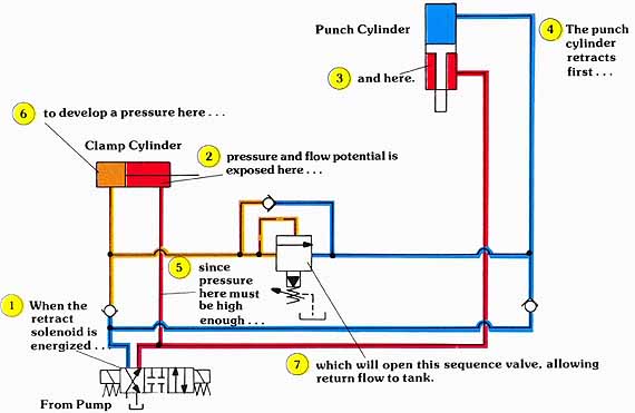
Depending on the mechanical design of the clamping mechanism, and the punch operation being performed, this example circuit may or may not provide satisfactory operation. That is, when the cycle is reversed, there is no assurance as to which cylinder will retract first. This will depend on which circuit has the path of least resistance to flow. Our example is given only to highlight the operating principle of a sequence application.
The example is but one of many sequence variations which could be used to solve the particular problem at hand. By the simple addition of two check valves in the circuit, we assure that during reversal of the circuit, the punch cylinder will always be the first to retract.
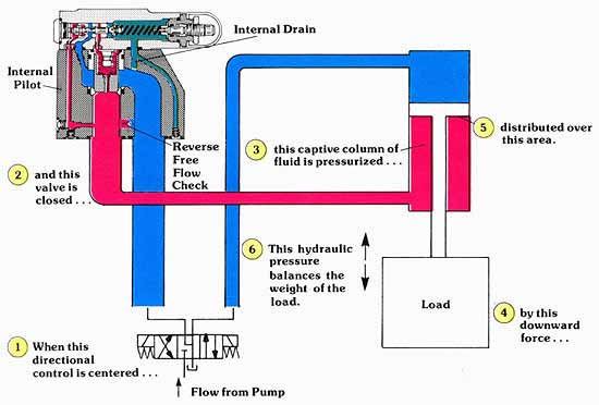
This circuit assures a specific order to the interaction of the clamp and punch circuits in both operating directions. It does not, however, assure a positive pre-determined clamping force in the retract mode. You will notice that the rod end of the clamp cylinder is also exposed to the pressure needed to retract the punch cylinder. Even though there is a captured column of fluid between the blind end of the clamp cylinder piston, the check valve, and the closed sequence valve, any leakage would create a tendency for the retraction of the clamping cylinder. Nevertheless, this circuit could provide sufficient clamping force for the withdrawal of the punch, especially on very tight systems with fast cycle rates.
USING A RELIEF VALVE IN A SEQUENCE APPLICATION
It is often possible to use a relief in a sequence operation, provided that the selected model can:
1. Be externally drained.
2. Withstand an operating system pressure on its outlet (tank) port. The only problem is that during valve operation, a continuous flow in the “Y” drain port exists.
In comparing the pilot section of the relief valve with that of the multi-function valve, you will notice one important difference. To keep the relief valve open, the pilot relief must be relieving fluid from the chamber on top of the main poppet. Depending on valve design and size, this pilot flow can be in the neighborhood of 3/4 to 1 1/2 GPM. At 3000 PSI, this can result in an efficiency loss of two or three horsepower. This heat generation and loss of speed in System II are not a problem with a multi-function valve used in a sequence operation.
One important advantage of the multi-function valve’s pilot head is that it opens and closes the main valve poppet with an insignificant amount of pilot flow. The actual flow required is only that which is displaced during stroking of the pilot spool. Likewise, the “Y” drain connection is only to rid the spring chamber of the oil which leaks by the pilot spool. Consequently, we can add to the overall efficiency of the total system by selecting the proper valve for sequence applications.
(See Color code legend for above image)
| Top of Page | PREV.: Pilot-Operated Multi-Function Valves | NEXT: Counterbalance Applications of Multi-Function Valves | Home |