| PREV.: Direct-Operated Multi-Function Valves | NEXT: Sequence Applications for Multi-Function Valves | Article Index | Home |
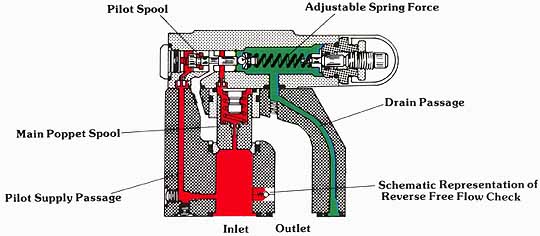
AMAZON multi-meters discounts AMAZON oscilloscope discounts The pilot-operated version of the multi-function pressure control can handle larger flow rates, generally with less pressure override than direct operated models. However, in most applications of the multi-function valve, pressure override is not nearly as critical as pressure override in relief applications. In fact, high pressure override characteristics can be desirable in some counterbalance applications. We will, however, postpone this discussion until we discuss applications of the multi-function valves. The cross-sectional illustration shows that the pilot section functions much like the direct operated valve. The only difference is that a high flow cartridge poppet is installed in series with the inlet of the pilot valve. Let us now consider the operation of this valve. |
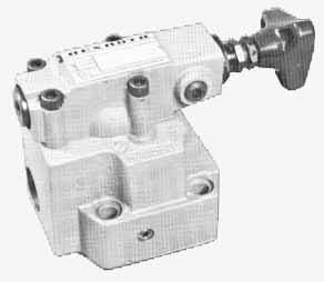
Above: A pilot-operated multi-function valve from Rexroth.
STATIC CLOSED CONDITION
In the closed condition, pressure in the pilot supply passage (“X”) cannot create a force large enough to overcome the set ting of the adjustable pilot spring. The pilot spring holds the pilot spool in the farthest left position, which closes the chamber above the main poppet. Through the orifice in the center of the main poppet, inlet pressure is exposed equally above and below the poppet. The slightly larger area, and the light spring force above the main poppet, keep the poppet closed as long as the pilot spool is held in position by the adjustable spring force.
(See Color code legend for above image)
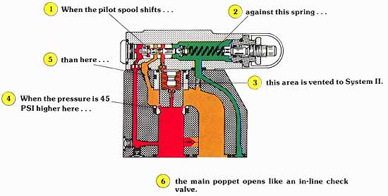
DYNAMIC VALVE OPENING
When pilot pressure is high enough to shift the pilot spool against the spring, the top side of the poppet is vented to System II pressure. Under these conditions, the main poppet functions like a simple in-line check valve. The valve allows flow from inlet to outlet as long as System I pressure is slightly higher (45 PSI) than that in System II. This pressure is needed to move the main poppet against the spring.
(See Color code legend for above image)
PILOT SPOOL DESIGN
Unlike the relief valve, it is desirable to have the multi- function valve open and close more gradually. Since the purpose of this valve is not to protect the system from over- pressure, a slower opening provides smooth transitions between the static and dynamic positions of the valve. In unloading and sequencing application, this minimizes the compression shocks normally referred to as water hammer. In counterbalance and braking applications, a cushioning is imposed on the movement of the load. Let us now look at the design of the pilot section to see how this gradual opening is achieved.
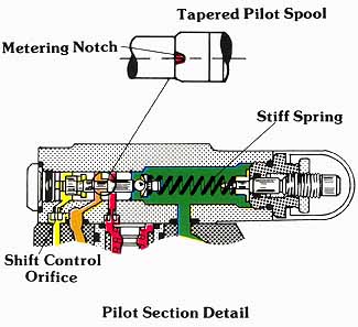
Above:
Pilot Section Detail. (See Color code legend for
above image)
If we want the main poppet to open slowly, we must provide a gradual decay in pressure above it. Likewise, in closing, the reestablishment of the static condition must be achieved gradually. This function is easily achieved by using a properly designed spool working in conjunction with a relatively stiff spring.
The pilot spool is designed with a slight taper on its sealing land. The edge of the land is also provided with ‘V” grooved metering notches. The combination of “V” grooves and tapered land provides for a gradual opening of the top of the main poppet to System II.
Although the pilot spool only strokes approximately 1/8”, the stiff spring also aids in gradual valve opening. That is, pilot pressure, which is sufficient to provide initial opening of the spool, may not be high enough to move it to the fully opened position. The net result is that, as pilot pressure builds on the left hand area of the pilot spool, the spool steadily strokes to the right against the spring. The top area of the poppet is vented through a gradually increasing orifice, which allows a smooth opening to System II. This opening, although related to set pressure for a given pilot spring, optimally occurs over a 100 to 150 PSI change in pilot pressure.
In some higher pressure applications, a high flow potential exists in the “X” pilot line. This high energy potential could adversely affect proper operation by causing the pilot spool to shift too quickly. To avoid this possibility, an orifice is in stalled in the supply line to the pilot spool end. This limits the flow potential to or from the pilot spool, which, in turn, restricts its shifting speed.
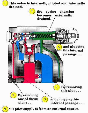
“X” and “Y” PORT CONNECTIONS
(See Color code legend for above image)
Note: Illustration is to show operating principles only. It does not depict the true port locations of NFPA standard mounting interfaces or access locations for internal plugs.
We have already discussed the possibility of converting internal and external pilot supplies and drains for the direct operated multi-function pressure controls. The cross- sectional illustration shows that the same possibilities exist for the pilot operated versions. The use of these various arrangements will be discussed in the application descriptions which follow.
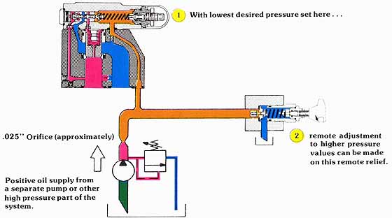
REMOTE PRESSURE ADJUSTMENT
One precaution which should be considered is that multi- function valves are not easily adjustable from an external source. First, we do not have an “X” port connection which can be used to modulate the pressure on top of the main poppet to a value lower than that set on the pilot valve. As already explained, the “X” port for multi-function valves serves an entirely different purpose.
Second, we cannot use the “Y” port method of remote adjustment. The problem here is that the only flow of oil into the spring chamber is leakage by the pilot spool. We do not have a positive oil supply as we did in the pilot section on either the pilot-operated relief or the reducing valve. Consequently, if remote adjustment is absolutely necessary, we must select an externally drained valve, and then supply the spring chamber with a positive pressure source. As shown in the following example, this method can be quite cumbersome.
(See Color code legend for above image)
| Top of Page | PREV.: Direct-Operated Multi-Function Valves | NEXT: Sequence Applications for Multi-Function Valves | Home |