| PREV.: Reducing Valve Symbols | NEXT: Pilot-Operated Multi-Function Valves | Article Index | Home |
AMAZON multi-meters discounts AMAZON oscilloscope discounts MULTIPLE FUNCTION PRESSURE CONTROLSIn industrial hydraulics there are basically three general purpose valve types available for pressure controls. We have already covered two of these types, namely, relief and reducing valves. This leaves us with the multi-function family of valves. Depending on the arrangement of pilot lines, drain lines, and the inclusion of an optional built-in reverse free flow check, these valves can perform various functions. The functions include: sequence, counterbalance, unloading, overcenter and braking. To complicate the selection even further, the valves are offered in both direct and pilot operated versions. We will first discuss the construction and variations of each and then will discuss their operation in various types of applications. |
DIRECT OPERATED MULTIFUNCTION VALVES
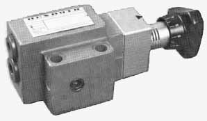
Above: A direct-operated multi-function valve from Rexroth.
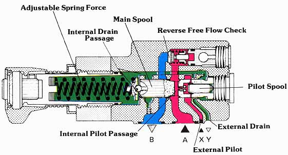
Multi-function valves are quite similar to relief valves in that the spring holds the spool or poppet in the closed position. Internal or external pilot pressure, from various sources, works against the spring, and causes the valve to open when the pressure setting has been reached. The working direction of flow is from the valve’s inlet to outlet, with both valve ports capable of withstanding full system pressure. Since these valves are often mounted in the service lines to the actuator, their housing is designed to accept an optional reverse free flow check. To better understand the various assembly possibilities, let us consider the following cross-sectional illustration.
Essentially, the valve consists of a spool which slides in a close fitting bore in the valve housing. The spool blocks the inlet from outlet, until the pressure on the right hand area of the spool overcomes the spring force. The small pilot spool serves to reduce the effective area on which pressure can work. You will notice that, with the spool installed, the net area is the same as the diameter of the pilot spool. Since the pilot spool slides in a clearance fit, oil leakage past this spool is connected to the drain passage.
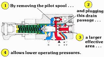
For lower pressure operation, the spool is removed, and the chamber on the right of the main spool is blocked from the drain passage with an internal plug. The valve will now shift at a considerably lower pressure, since the effective area is now the full diameter of the main spool.
(See Color code legend for above image)
(See Color code legend for above image)
“X” PORT PILOT PRESSURE CONNECTION
As shown in the illustration, the pilot pressure can be taken internally from the valve’s inlet through axial and radial drillings in the spool. For internally piloted valves, the external “X” connection is plugged in the valve housing. With this assembly, the valve works much like a relief valve, in that pressure at the valve’s inlet shifts the spool to an open position once the pressure setting has been reached. As will be shown, internally piloted valves are normally used in sequence and some counterbalance applications.
(See Color code legend for above image)
“X” Pilot Conversion
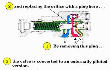
For other applications, it is usually necessary to have the valve shift in relationship to a pressure in another part of the circuit. By opening the external connection and replacing the orifice in the spool with a plug, the pressure signal is converted to some external source. In this assembly, the pressure at the valve’s inlet can build to the pressure setting of the main system relief, even if the pressure required to shift this valve is set quite low. The valve will not open until it is signaled to do so by the external source. As will be shown, this assembly is generally used for unloading and over-center type counterbalancing applications.
(See Color code legend for above image)
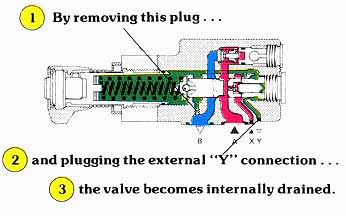
“Y” Drain Conversion
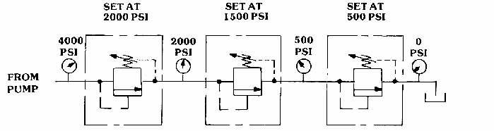
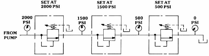
Back pressure in the spring chamber is additive to the pressure setting of the valve, as it is in any type of pressure control. Generally speaking, multi-function valves can be internally drained whenever the valve’s outlet is connected to tank during the period when the valve is functioning. If an operating system pressure is developed in the valve’s outlet, it must be externally drained. With some counterbalance and most unloading applications, the valve can be internally drained. The effects of internal or external draining are shown in the following examples of multi-pressure valves, connected in series:
Above:
Internally Drained Valves Function Like Resistances in Series
Above:
Externally Drained Valves Are Not Affected By Downstream Pressure
| Top of Page | PREV.: Reducing Valve Symbols | NEXT: Pilot-Operated Multi-Function Valves | Home |