Hydraulic Reducing Valve Symbols

PREV.: Reducing Valve with Primary Control and Heat Generation with Pressure-Reducing Valves NEXT: Multiple Function Pressure Controls Article Index Home


AMAZON multi-meters discounts AMAZON oscilloscope discounts

Like pressure-relief valve symbols, reducing valve symbols can represent either direct or pilot operated valves. You will notice that symbols for reducing valves are similar to those of relief valves, except for two major changes.

First, since the reducing valve is normally open, the flow arrow is in line with the inlet and outlet ports to the square box. This shows that the valve passes fluid freely until pilot pressure overcomes the spring force. At this point, the flow arrow is pushed out of alignment with the inlet and outlet, which closes off the flow.

Second, since the reducing valve is sensing pressure at its outlet, the pilot line differs from that of the relief. In the reducing valve symbol, the pilot line works against its control spool by sensing outlet pressure. Also, since a reducing valve must always have a drain connection to its spring chamber, the “Y” port external drain is always shown.

Various reducing valve symbols are shown below:

   
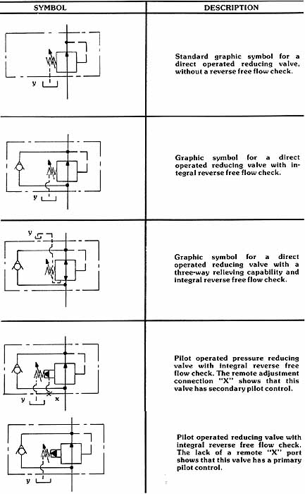
Above: Hydraulic Reducing Valve Symbols. If you can't read the text, hover your cursor over each symbol for a pop-up text caption to appear.

Top of Page PREV.: Reducing Valve with Primary Control and Heat Generation with Pressure-Reducing Valves NEXT: Multiple Function Pressure Controls Home

Wednesday, March 4, 2020 9:57

Make-Up Check Port Relief Valve Directional Control From Pump From Pump Directional Control Fly wheel Hydraulic Motor Crossport Reliefs X port Y drain P1 P2 Tank 1. When the pilot relief opens... 2. a constant pilot flow is established... 3. by this pressure compensated flow control. 4. The pressure in the pilot circuit determines... 5. the outlet pressure on this area needed to close the main spool. 6. The main spool orifices flow to the secondary system, which keeps outlet pressure in equilibrium with pilot pressure. Main System Flow (GPM) Inlet to outlet pressure: 3000 PSI delta P, 1500 PSI delta P Pilot Flow in^3/Min 3. This feeds back an inaccurate downstream pressure... 4. and lessens the pilot oil flow. 2. creates turbulence downstream of the main control spool. 1. A high flow rate… Pressure Compensated Flow Control Metered Pilot Flow Pilot Relief Over Pressure Relief Protection Drain Port High Pressure Inlet Reduced Pressure Outlet Gauge Port 1. When this pilot relief is closed... 2. the pressure above the control spool is the same... 5. Consequently, the main control spool is held in the WIDE OPEN POSITION, since there is a larger opening force than closing force. 4. The pressure at the outlet is only slightly lower than that at the inlet because of pressure drop due to flow. 3. as the pressure at the inlet, since the pilot system is static. 1. When the secondary system become static... 2. leakage by the main control spool… 3. could cause downstream pressure to equalize... 5. However, this relief opens when pressure builds to 45 PSI above that set on the pilot... 4. with inlet pressure... 6. which limits the pressure build-up downstream of the valve. Symbol DESCRIPTION Standard graphic symbol for a direct operated reducing valve, without a reverse free flow check. Graphic symbol for a direct operated reducing valve with integral reverse free flow check. Graphic symbol for a direct-operated reducing valve with a three-way relieving capability and integral reverse free flow check. Pilot operated-pressure reducing valve with integral-reverse free-flow check. The remote adjustment connection X shows that this valve has secondary pilot control. Pilot-operated reducing valve with integral-reverse free flow check. The lack of a remote X port shows that this valve has a primary pilot control.