| PREV.: Pilot-Operated Reducing Valves | NEXT: Symbols | Article Index | Home |
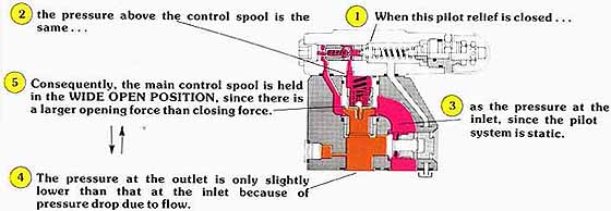
AMAZON multi-meters discounts AMAZON oscilloscope discounts Before we discuss the operation of a reducing valve with primary control, let us first consider the reason for this design. It is a known fact that when an orifice is introduced into a flow stream, turbulence is also introduced, down stream of the orifice, Of course, the higher the flow rate, the more turbulence downstream of any given orifice. With high flow, high pressure reducing valves, the turbulence downstream of the main control spool causes a loss in pressure at that point in the flow stream (Venturi effect). This loss in pressure reduces the pressure drop across the pilot circuit orifices, which lessens the pilot oil flow. Under these conditions, a reducing valve with secondary control becomes ineffective in maintaining a constant downstream pressure. |
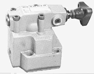
Above: A Reducing Valve with Primary Control
When the piloting relief opens, a decay in pressure occurs above the main control spool, since a flow is created across the orifices in the pilot circuit. This causes an imbalance of forces on the main spool, which tends to move it vertically upward. An upward motion of the spool orients the center line of the radial drilling in the spool higher than the center line of the radial drilling in the stationary sleeve, in which it slides. The open area for flow is, thus, reduced, creating an orifice through which oil must flow in passing from the primary to the secondary port. Hence, a self-regulating pressure drop is imposed, in concert with the pressure levels dictated by the pilot circuit. Likewise, a full shut-off occurs when the secondary circuit becomes static.
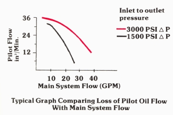
Above: Typical Graph Comparing Loss of Pilot Oil Flow With Main System
Flow
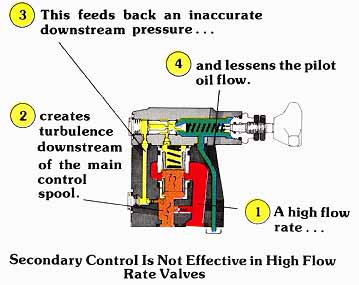
Above: Secondary Control Is Not Effective in High Flow Rate Valves. (See
Color code legend for above diagram)
A reducing valve with primary control can be used, to achieve higher flow rates with better stability. With this design, the pilot oil is supplied from the high pressure inlet of the valve. The pilot head incorporates a pressure compensated flow control which maintains a pilot flow of approximately 40 in.3/min flow stream. Since the top of the main control spool is exposed to this pilot flow, the force holding the valve open is determined by the pressure setting of the pilot relief. Let us now consider the operation of this design.
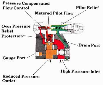
Above: (See Color code legend for above diagram)
As long as the inlet pressure is lower than the setting of the pilot relief, the pressure on top of the main spool is equal to the pressure at the inlet of the valve. This pressure force, along with the spring force, holds the main spool in the wide open position, allowing free flow to the secondary circuit. As load induced pressure increases, so does the inlet pressure and the force holding the main spool open.
Above: (See Color
code legend for above diagram)
The moment the inlet pressure exceeds the setting of the pilot relief, a constant pilot flow is established. The pressure determined by the pilot relief regulates the maximum pressure, holding the reducing valve in the open position. As load induced pressure increases on the opposite area of the main control spool, so does the force trying to close the valve. The moment the closing force exceeds the forces holding the valve open, the main spool moves upward, orificing the flow to the secondary circuit. Hence, secondary system pressure is maintained at a level which balances the pressure in the pilot circuit.

Above: (See Color code legend for above
diagram)
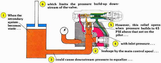
When the actuator on the reducing valve’s outlet stalls, a slight increase in outlet pressure overcomes the forces holding the valve open, and moves the main spool to the fully closed position. Under these conditions, the secondary outlet is totally isolated from the primary circuit and the pilot circuit of the valve, Of course, leakage across the sliding fits of the main control spool could cause the secondary system pressure to equalize with that of the primary system.
To avoid the possibility of pressure build-up in a static secondary circuit, a small relief valve is incorporated in the main spool. This relief valve has its pressure port exposed to the secondary outlet, and relieves oil to the pilot circuit. The relief valve is nothing more than a ball held on its seat by a light spring force. To open this relief, the pressure in the secondary circuit must overcome the spring force (45 PSI) and the pressure in the pilot circuit working against the back side of the ball. However, since outlet pressure is equal to pilot pressure, the net result is that the relief valve opens when the secondary system reaches a pressure 45 PSI higher than setting. Since the relief valve relieves oil to the pilot circuit, its maximum flow capability is limited to ap proximately 60 cubic inches per minute. Although this is satisfactory for relieving leakage oil, it cannot relieve a re verse flow from the actuator.
Above: (See Color code legend for above diagram)
REMOTE PRESSURE ADJUSTMENT FOR PRIMARY CONTROL REDUCING VALVES
As shown, this design does not modulate the pressure above and below the spool (or poppet) in the conventional pilot operated manner. Since there is no “X” port where we can remotely modulate the pressure above the main control spool, we must use the “Y” port to create this function. A complete description of the use of the “Y” port for remote adjustment, and of the precautions to be taken in its use, has been given in the section of this manual which deals with pilot operated relief valves.
HEAT GENERATION WITH PRESSURE REDUCING VALVES
Reducing valves, in general, are unique in their ability to in dependently adjust force in a secondary system. Likewise, they are the only valves which can be used to isolate components with low pressure ratings from the rest of the higher pressure system. However, we caution the designer to be discrete in his selection of a reducing valve function. We must always weigh the design flexibility offered by reducing valves against their undesirable heating capability.
The pressurized fluid at a reducing valve’s outlet has less potential for doing work than the fluid which was exposed at its inlet. This is true since a loss in pressure shows up down stream as a loss of force potential. Since energy cannot be destroyed, the loss of energy shows up as heat in the hydraulic system. Of course, the lower the pressure in the secondary system, the more heat is generated. Remember:
BTU/hr= 1.5 x GPM x PSI (Lost)
Consequently, it is left to the designer to keep the secondary system pressure as close to that in the primary system as possible. You can see that this becomes even more important in high flow systems. In these, if the pressure differential is too great, it is worthwhile to consider a separate pump for the lower energy secondary system.
| Top of Page | PREV.: Pilot-Operated Reducing Valves | NEXT: Symbols | Home |