| PREV.: Direct-Operated Valves | NEXT: Reducing Valve with Primary Control | Article Index | Home |
AMAZON multi-meters discounts AMAZON oscilloscope discounts
Like pilot-operated relief valves, pilot-operated reducing valves perform the same function as their direct operated counterparts. Consequently, pilot operated reducing valves must be used for higher flow rates, since increased spring force, with increased displacement, has adverse effects on the performance characteristics of direct operated models. Today pilot operated pressure reducing valves are designed with both primary and secondary controls. We now wish to study the operation and characteristics of both of these types.
We will discuss the operation of the secondary control first, since this valve is really nothing more than a mirror image, so to speak, of a pilot operated relief valve. First of all, you will notice that the pilot section senses pressure in the secondary (outlet) port rather than the inlet, as with relief valves. As long as the pilot relief remains closed, pressures are equal above and below the main control spool. You will notice that the light spring force holds the main control spool in the fully open position, while, in contrast, the relief valve is held closed in the static pressure balanced condition. The valve remains fully open, connecting the primary port to the secondary system until secondary system pressure overcomes the spring setting of the pilot valve.
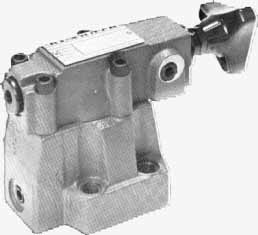
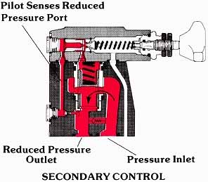
Above: (left) a typical pilot-operated reducing valve; (right) secondary control -- a cross section of the Rexroth valve on the left (See Color code legend for above image)
When the piloting relief opens, a decay in pressure occurs above the main control spool, since a flow is created across the orifices in the pilot circuit. This causes an imbalance of forces on the main spool, which tends to move it vertically upward. An upward motion of the spool orients the center line of the radial drilling in the spool higher than the center line of the radial drilling in the stationary sleeve, in which it slides. The open area for flow is, thus, reduced, creating an orifice through which oil must flow in passing from the primary to the secondary port. Hence, a self-regulating pressure drop is imposed, in concert with the pressure levels dictated by the pilot circuit. Likewise, a full shut-off occurs when the secondary circuit becomes static.
Above: (See Color code legend for above
image)
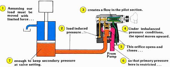
In the dynamic closed position of the pilot operated reducing valve, the spool moves completely upward so that, theoretically, there is no flow area through the radial cross drillings. This position occurs, though only in theory, since there must be a flow of fluid in the pilot circuit to maintain the imbalance on the main spool. To better explain the dynamic closing we will consider a vertical acting, “bottomed out” cylinder.
RELIEVING ABILITY OF PILOT OPERATED REDUCING VALVES
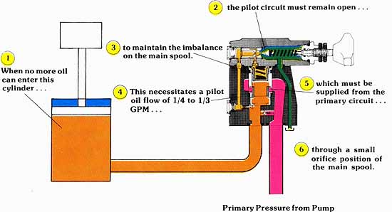
Unfortunately, as you can see in the diagram below, the pilot-operated reducing valve has little ability to rapidly relieve a pressure build-up due to increased load. When the secondary circuit becomes static, the main spool is nearly closed, which except for a small pilot flow, captures a column of fluid between the main spool and actuator. If, for some reason, the actuator encounters an increased load, the pressure down stream of the reducing valve will also increase. Since pilot operated reducing valves, in general, cannot relieve much more than a 1/2 GPM flow rate through their pilot circuits, a separate relief valve should be considered if an increase in load could occur after the secondary system becomes static.
Above: (See Color
code legend for above diagram)
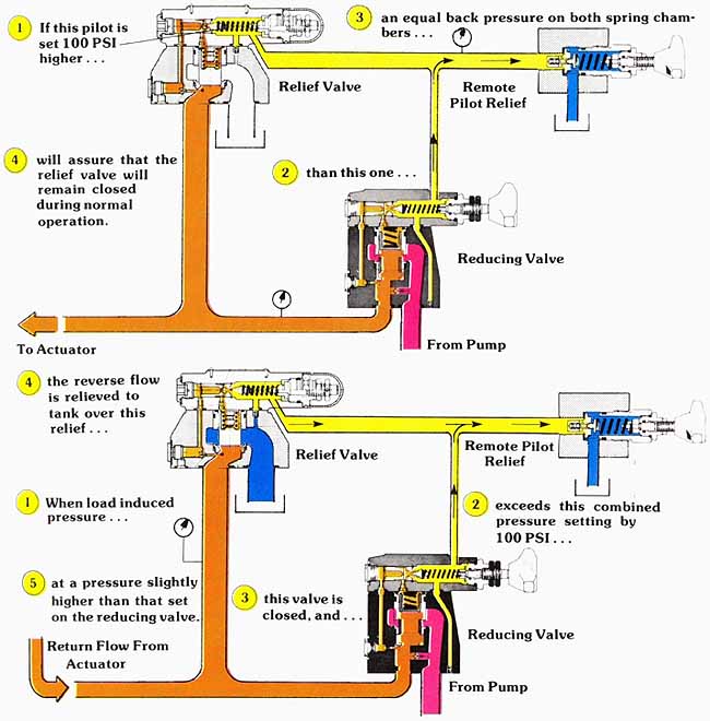
THREE-WAY PRESSURE REDUCING CIRCUIT
When it is necessary for the actuator to “give way” to an excessive load, a separate relief valve can be incorporated to relieve the reverse displacement from the actuator. Actually, this relief valve need be nothing more than a direct operated model, teed into the line between the reducing valve and the actuator. However, a pilot operated model offers better performance characteristics, and the possibility of fail-proof pressure setting. With this type of circuitry, it is important, from an efficiency standpoint always to adjust the relief valve to a pressure slightly higher than that set on the reducing valve. By setting the relief so that it will crack at a pressure of 100 to 200 PSI higher, you can be assured that under nor mal operation, all the output flow of the reducing valve produces work. If the relief valve setting is too close to that of the reducing valve, you can easily see that the flow bypassed by the relief not only affects performance, but that, at the same time, it generates excessive heat. The circuit provides a single pressure adjustment, while at the same time it maintains a constant differential between the relief and reducing valve setting.
Above: (See Color code legend for above
diagram)
REVERSE FREE FLOW
Since reducing valves are often used in the working lines sup plying the actuator, the reducing valve must be able to allow a free flow in the reverse direction. Since the reducing valve is normally open, one would think that there would be no problem in passing a reverse flow through the valve. Unfortunately, with some circuits, you cannot safely assume that the valve will always remain open.
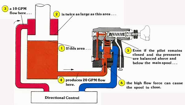
It is possible that high flow forces (hydrodynamic forces) could cause
the main spool to close. This consideration is particularly important when
you are using cylinder actuators with large rods. Under these conditions,
a 2:1 ratio can double the normal flow rate.
Above: (See Color code legend for above
diagram)
In the illustrated circuit, once the reducing valve closes, pressure can build in the fluid which is captured between the actuator and the closed spool. If this pressure builds to the point where the reducing valve pilot opens, the main spool will remain closed. Since we cannot safely assume that the spool will remain open under all circumstances, most reducing valves include a reverse free flow check as a standard feature.
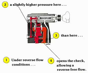
Above: (See Color code legend for above diagram)
As shown in the cross-sectional drawing above, the check valve simply bypasses the reducing valve mechanism under reverse flow conditions. During normal operation, the higher pressure at the valve’s inlet keeps the check valve closed.
| Top of Page | PREV.: Direct-Operated Valves | NEXT: Reducing Valve with Primary Control | Home |