| PREV.: Reducing Valves | NEXT: Pilot-Operated Reducing Valves | Article Index | Home |
AMAZON multi-meters discounts AMAZON oscilloscope discounts For the same reasons, direct operated relief valves normally experience bad pressure override characteristics. With respect to increasing flow, direct operated pressure reducing valves show a drop in outlet pressure. To explain this phenomenon, we can consider the operation of a direct acting reducing valve. |
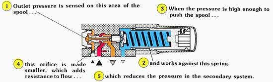
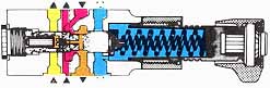
Above: (See Color code legend for above image)
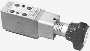
Above: A Direct-Operated Valve (made by Rexroth)
Because reducing valves are variable orifices, their basic design is usually a tapered (metering) spool, held in the open position in the valve housing by an adjustable spring force. For direct operated valves, outlet pressure is exposed to the spool end opposite the spring, and moves the spool toward a more closed position as downstream pressure exceeds the spring setting. Because the orifice can be relatively large for high flows, the spring has to be only slightly compressed. However, to establish an identical pressure drop for low flow, the spring must be compressed further to create a smaller passage through the valve. Consequently, higher downstream pressure results with a decreased flow due to in creased spring force.
Since pressure vs. flow characteristics can only be kept within acceptable limits with low variations in flow, Rexroth only manufactures direct operated reducing valves up to 1/2” line sizes for flow capabilities up to 12 1/2 GPM. For higher flows, a pilot operated valve is used because of its performance advantages.
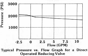
Above: Typical Pressure vs. Flow Graph for a Direct Operated Reducing Valve
Three-Way Characteristics of Direct Operated Valves
Another thing to consider about reducing valves is their ability to maintain reduced pressure in a fully static condition. During actuator motion in the secondary circuit, we have explained how the reducing valve modulates between open and closed to maintain downstream pressure at the desired setting. A problem arises, however, when the secondary circuit becomes static, and the reducing valve fully closes to separate the primary and secondary system pressures.
Under these conditions, an increase in load, or leakage across the reducing valve control spool, could increase the pressure in the secondary circuit higher than is desired. Since the valve has an inlet at high pressure, and an outlet at reduced pressure, a third port must be provided to rid the secondary circuit of leakage oil and/or reverse flow from the actuator. Most reducing valve designs in some way vent this oil, which tends to increase pressure to the spring chamber, where the oil can be externally drained.
Static Venting And Reverse Flow Capability
The easiest method of venting oil, which tends to build pressure in the secondary circuit, is to have a bleed oil passage from the secondary port to the spring chamber. This leakage path, however, adds to the amount of flow out the drain port, which decreases the efficiency of the valve.
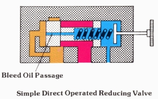
Above: Simple Direct Operated Reducing Valve.
Some direct operated reducing valves have a three-way spool configuration. We previously stated that the reducing valve is normally open, and that it opposes the spring force with a hydraulic force from the secondary circuit. Depending on the pressure and flow potential at the valve inlet, the valve self-adjusts its orifice to obtain the required pressure loss. The valve closes only when the secondary circuit becomes static. A slight increase in outlet pressure above pressure set ting shifts the spool further against the spring into a third position where the outlet is connected to the spring chamber, thus relieving the secondary circuit to tank. The flow capability of this three-way feature is approximately 20% of the maximum flow capacity of the Rexroth valve. When the secondary circuit is stalled, and there is no increase in pressure due to leakage, thermal expansion, or increased load, the valve is closed without leaking excessive oil to tank.
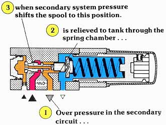
Above: 3-Way Reducing Valve
Sandwich Mounted Reducing Valves

Above: Sandwich-Mounted Reducing Valve
In many hydraulic systems, the reducing function is only needed for one particular actuator. For instance, we may want to limit the torque output of a hydraulic motor, or to limit the thrust of a cylinder in one or both directions. For plumbing convenience in these types of circuits, reducing valves are available for sandwich mounting. These valves are simply mounted between the subplate and the directional control for that particular circuit function.
Depending on the model selected, the pressure reduction can be in the pressure supply to the directional valve, or in one of the service lines from the directional control to the actuator. A “P” port sandwich reducer would offer reduced pressure to either direction of operation. Since the flow is always from the pump supply, through the reducing valve to the pressure port of the directional control, a reverse free flow check is not required.
On the other hand, if the model selected reduces pressure in one of the service lines to the actuator, pressure control is achieved only in one direction of operation. Full system pressure operates the actuator in the reverse direction. Of course, since flow must pass through this type of valve in both directions, a reverse free flow check valve must be included. This allows the flow to by-pass the reducing valve mechanism in the reverse direction of actuator operation.
Due to their compact design, sandwich mounted reducing valves normally drain their spring chambers to the tank port connection of the directional valve. Since pressure in the tank return line can influence the pressure setting, precautions should be taken to keep tank line pressure as low as possible in these systems.
| Top of Page | PREV.: Reducing Valves | NEXT: Pilot-Operated Reducing Valves | Home |