| PREV.: Symbols for Pilot-Operated Reliefs | NEXT: Direct-Operated Valves | Article Index | Home |
AMAZON multi-meters discounts AMAZON oscilloscope discounts As previously stated, reducing valves are used to limit a branch circuit to a pressure lower than the main relief valve setting. Consequently, output force can be regulated in the secondary circuit independent of (at a lower pressure level than) the rest of the system. Reducing valves are always sup plied with an external drain on the spring chamber, since there is always pressure at the inlet and outlet working ports during valve operation. Reducing valves, like relief valves, function by balancing a hydraulic force with a spring force. Consequently, they display similar operating characteristics to those of direct operated or pilot operated reliefs. Unlike relief valves, however, reducing valves are normally open, allowing oil en try to the secondary system. The valve senses the pressure level in the secondary system and tends to close, orificing the oil entering from the primary system, assuming that it is at a higher pressure level. Should the primary system be at a lower pressure level than the setting on the reducing valve, then the reducing valve would remain fully open, and both primary and secondary circuits would be at the pressure level of the primary system. |
Reducing valves, more than any other type of pressure control, modulate between fully open and fully closed positions to keep the outlet pressure constant. Once downstream pressure reaches the reducing valve setting, the valve begins functioning as a self regulating orifice. The valve opens or closes its orifice which reduces or increases resistance to flow from inlet to outlet.
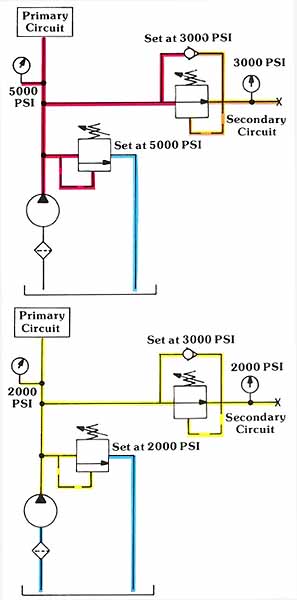
Above: Reducing valves can take only a higher primary pressure and lower it for the secondary circuit. (See Color code legend for above image)
This symbol is complete in showing the main poppet (low pressure, high volume relief), the pilot relief (high pressure, low volume), the orifices which establish pressure decay in the pilot circuit, and the solenoid valve for venting. In common practice, the industry does not use symbols of this complexity. Over the years, it has become standard practice to represent both pilot operated and direct operated reliefs with the simpler direct operated relief valve symbol. This, however, often leads to confusion, since the total function cannot be represented in this manner. Rexroth has developed and will be promoting the use of a new simplified symbol for representing pilot operated reliefs.
Since a reducing valve is nothing more than a self regulating resistance to flow, energy is expelled in the form of heat as inlet pressure is reduced to a lower outlet pressure. The higher the pressure level difference, the higher is the energy level difference and, therefore, the more energy is wasted in the form of heat. Large pressure differentials, especially with high flow rates, should be avoided through the use of a two pump system.
| Top of Page | PREV.: Symbols for Pilot-Operated Reliefs | NEXT: Direct-Operated Valves | Home |