Symbols for Hydraulic Pressure-Control Valves

PREV.: Hydraulic Accumulator Unloading Valves NEXT: Conclusion Article Index Home


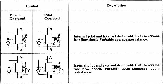
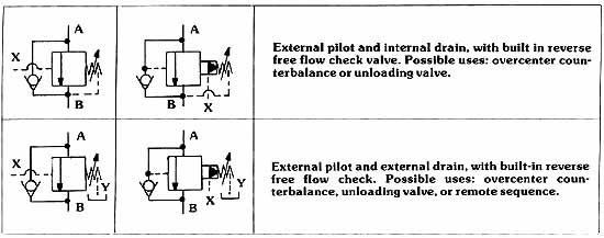
AMAZON multi-meters discounts AMAZON oscilloscope discounts

Since the function of a multifunction valve so closely resembles that of a relief valve, you will notice that the symbols are quite similar. Of course, most multifunction valves include a reverse free flow check, which must also be represented in symbolic form. In the following examples, you will understand the specific valve function being represented by paying strict attention to the arrangement of pilot lines.

MULTI-FUNCTION VALVE SYMBOLS


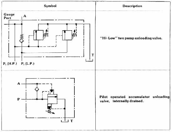
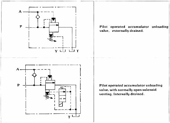
SPECIALTY VALVE SYMBOLS


Hydraulic line color-coded legend. Used in schemaics.

Top of Page PREV.: Hydraulic Accumulator Unloading Valves NEXT: Conclusion Home

Wednesday, March 4, 2020 10:05

Make-Up Check Port Relief Valve Directional Control From Pump From Pump Directional Control Fly wheel Hydraulic Motor Crossport Reliefs X port Y drain P1 P2 Tank 1. When the pilot relief opens... 2. a constant pilot flow is established... 3. by this pressure compensated flow control. 4. The pressure in the pilot circuit determines... 5. the outlet pressure on this area needed to close the main spool. 6. The main spool orifices flow to the secondary system, which keeps outlet pressure in equilibrium with pilot pressure. Main System Flow (GPM) Inlet to outlet pressure: 3000 PSI delta P, 1500 PSI delta P Pilot Flow in^3/Min 3. This feeds back an inaccurate downstream pressure... 4. and lessens the pilot oil flow. 2. creates turbulence downstream of the main control spool. 1. A high flow rate… Pressure Compensated Flow Control Metered Pilot Flow Pilot Relief Over Pressure Relief Protection Drain Port High Pressure Inlet Reduced Pressure Outlet Gauge Port 1. When this pilot relief is closed... 2. the pressure above the control spool is the same... 5. Consequently, the main control spool is held in the WIDE OPEN POSITION, since there is a larger opening force than closing force. 4. The pressure at the outlet is only slightly lower than that at the inlet because of pressure drop due to flow. 3. as the pressure at the inlet, since the pilot system is static. 1. When the secondary system become static... 2. leakage by the main control spool… 3. could cause downstream pressure to equalize... 5. However, this relief opens when pressure builds to 45 PSI above that set on the pilot... 4. with inlet pressure... 6. which limits the pressure build-up downstream of the valve. Internal pilot and external drain, with built-in reverse free flow check. Probable uses: sequence, counterbalance. Internal pilot and internal drain, with built-in reverse free flow check. Probable use: counterbalance. Description Pilot-Operated Direct-Operated Symbol External pilot and external drain, with built-in reverse free flow check. Possible uses: overcenter counterbalance, unloading valve, or remote sequence. External pilot and internal drain, with built in reverse free flow check valve. Possible uses: overcenter counterbalance or unloading valve. Pilot operated accumulator unloading valve, internally drained. Hi- Low two pump unloading valve. Description Symbol Pilot operated accumulator unloading valve, with normally open solenoid venting. Internally drained. Pilot operated accumulator unloading valve, externally drained.