AMAZON multi-meters discounts AMAZON oscilloscope discounts
__3.7 Horizontal single-stage double-suction axially-split pumps (for general purposes)
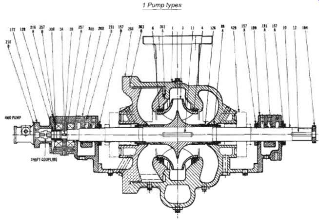
Fig. 10 Double-suction process pump to API 610/ISO 13709
Thirty-five years ago the double suction pump was the predominant water pump for applications where the pipe size exceeded 200 mm. The classic design with a large impeller between two bearings, two stuffing boxes and axially-split pump casing with the pipe connections in the lower half, Fig. 9, is still used for large flows at low heads.
The specific speed per impeller, half for double suction impeller type pumps, is less than that of similar single suction pumps and this results in a corresponding flattening of the H-Q curve.
In borderline cases the lower NPSHr value means that higher speeds can be used. In special instances where it’s desirable to maintain as near pulsation-free flow as possible, as for example, fan pumps for paper machines, double suction pump impellers with staggered blades are used. Sometimes the location of the pump connection flanges can make the use of a double-suction pump advantageous.
Water temperature can be up to 120 degr. with standard cast iron casings. Special bronze casings are sometimes supplied for seawater applications. Impellers can be cast iron or bronze.
Pumps with 250 mm connections can handle 1200 m^3/h at 100m. Larger pumps are available for up to 40000 m^3/h at 40m.
Small pumps have pressure ratings of up to 17 barg reducing to 5 barg for the largest sizes. Power requirements are up to 5.5 MW. Packed stuffing boxes or mechanical seals can be fitted as options.
This style of pump has been available in the past in two slightly different two-stage versions. A two-stage pump with single entry second stage was used as a condensate extraction pump for steam turbo-generators. The pump grew to unmanageable proportions in the 1960s as generators became much larger.
The design concept changed and the condensate extraction pump became a vertical multi-stage pump. A two-stage pump with two double entry impellers has also been available, particularly in the United States. This style of pump was designed when axial thrust was not fully understood and resulted in a hydraulically balanced rotor. Neither of the two-stage designs described here are popular currently in pump applications.
__3.8 Horizontal single-stage double-suction radially-split pumps (for heavy-duty applications includes ISO 13709, API 610 designs)
This pump, see Fig. 10, is not as popular as the end-suction pump. It’s similar in some respects to Part. 3.7 pumps but has center-line mounted radially split casings. Generally with top-top process connections, but side-side and other variations are available. The double entry impeller mounted between two bearings. Rolling bearings are standard, sliding bearings and various lube oil systems can be made to order.
The mechanical seals can be serviced by removing the coupling and bearing housings. A spacer coupling is required. The rotor assembly is withdrawn from the casing, away from the driver.
These pumps tend to be slightly larger than the end-suction pumps. Flows over 5000 m^3/h are possible at heads up to 500m. Suction sizes from 8" to 16" are popular with pressure ratings up to 60 barg. Materials and flanges are similar to Part. 3.6 types.
__3.9 Horizontal two-stage end-suction overhung impeller centrifugal pumps
These pumps are a logical extension to the single-stage pumps described earlier. The design problem to overcome is shaft deflection. The weight of both impellers is cantilevered from the front bearing. Also remember that some space must be left for shaft sealing, further increasing the overhang. Pumps for benign liquids, in days past, could be sealed by a simple soft-packed arrangement. This simple, but very effective arrangement also provided a useful degree of support and damping for the shaft. These effects helped to minimize vibration.
The primary disadvantage to soft-packing is the skill required to pack a box, run the packing-in, and then nurture the packing throughout its useful life with tender loving care. These skills are disappearing and there is no time, now, to bed packing-in properly followed by almost continuous adjustment. The modern mechanical seal is seen as a gift from heaven for accountants, but provides no shaft support and no damping. Shaft diameters must be increased to limit shaft deflection and to increase critical speeds. There is a point reached, when shaft diameter increases, that a between-bearing pump is almost cost comparable ...... except that it has two mechanical seals, not one! Fig. 11 shows a novel approach to the two-stage concept.
The first stage is mixed-flow rather than truly radial. This combination allows the return passage of the diffuser to be slightly smaller than the tip diameter of the second radial stage. The design produces an effective back pullout assembly which greatly enhances maintainability, leaving the casing in situ and process connections undisturbed. Both stages have front and back wear rings; these will provide some dynamic stability as well as reducing internal leakage. This style of pump is aimed at the process industries, particularly paper making. These pumps, in super-duper 25Cr 5Ni 2Mo, can handle 1080 m^3/h and produce differential heads of 220 m. The casings are designed to cope with 25 barg and 180 degr.
The two-stage overhung pump is vigorously disliked by API and many in the Oil & Gas industry. This is probably due to past failures and unreliability. The Oil & Gas industry was renowned though for getting duty conditions wrong in the past, and this pump design may have attracted an unwarranted reputation.
This style of design will be susceptible to vibration, rubbing and seizure when operated well away from BEP, if gas slugs pass through and if started without being primed properly. All of these happen regularly in the Oil & Gas environment. These pumps would tend to fair much better when not used for water and selected for a minimum viscosity 4 cSt. The wear rings would perform as much better bearings.
Future developments will probably center on enhanced bearing materials for the wear rings; the first stage wear rings at least. Improved bearing performance will allow larger pumps to run successfully. Fig. 12 shows a style of wear ring which may become common. Alternatively, a ceramic rolling-contact bearing may be a more reliable option for very clean liquid applications.
__3.10 Vertical single-stage overhung impeller centrifugal pumps for general applications
Vertical single-stage pumps, pumps which have a suction connection and are not submerged, fall into two basic design types.
Some pumps use standard electric motors and have flexible couplings. These pumps have radial and thrust bearings in the pump. The other pump design requires a special electric motor; an electric motor with a thrust bearing. The pump includes a radial bearing but relies on the electric motor for axial setting. Also available, is an almost off-the-shelf horizontal end-suction pump which is mounted vertically. A short, bent pipe section is attached to the usual suction connection to obtain the 'inline' configuration. Vertical single-stage pumps in this category are similar to central heating circulators ...... but …the pump must be supported! The pump does not hang in the pipework; they are too heavy for that.
Pumps with a bearing bracket follow the design rules of horizontal end-suction pumps and use a number of the same parts.
A motor stool is used to support the flanged motor from the pump. These pumps can save floor space but the piping arrangement must be appropriate. Small pumps can handle 400 m^3/h while the largest pump can pass 3500 m^3/h. Differential head can be from 230 m to 900 m. Some pumps can cope with quite cold liquid, down to 185 degr. and up to about 400 degr. Pressure ratings can be light, 24 barg, to heavy-duty, 100 barg.
These pumps can utilize the flexible coupling of purchaser's choice. A wide range of material combinations is possible to suit most applications. Mechanical seal chambers may comply with ISO 21049/API 682 requirements. There are mag-drive versions available when leaks are intolerable.
The pumps without a bearing bracket, like their horizontal equivalents, produce a very small, neat package. Thrust bearings in the motor absorb the pump axial thrust and locate the impeller in the casing. Motor bearings will usually be grease-lubricated and can be re-greased while running. The motor can have a special extended shaft for mounting the impeller directly, or be connected via a solid muff coupling. The coupling can incorporate the pump axial setting adjustment. Space for a mechanical seal is likely to be restricted; double seals with "bells and whistles" might not be possible. Benign liquids, with just traces of hazardous/toxic compounds, might be out-of-bounds.
However, it’s possible to squeeze a lot out of these little packages; variable speed motors are becoming more popular.
Matching the pump to the process conditions, to save energy, is worthwhile economically. Speeds up to 8000 rpm are possible.
Small pumps are limited to 25 m^3/h at differential heads up to 600 m. Larger pumps can handle 500 m^3/h with slightly less head rise, 275 m. Casing design pressures of 40 bar(g) are typical and designs cope from -40 to 400~ One of the most prevalent problems associated with these pumps, is poor piping layout. It’s not unusual to see these pumps in a dogleg from a long, straight, pipe run. The straight length of pipe on the suction connection is usually too short; 5D is the rule-of-thumb for a minimum. Increased turbulence in the impeller produces vibration leading to wear and short bearing life. In a number of cases, the vertical pump was the wrong style for the equipment layout; an end-suction pump would have better!
Fig. 11 A horizontal two-stage end-suction pump
Sulzer Pumps
Fig. 12 Wear rings for better bearing performance
__3.11 Vertical single-stage overhung impeller centrifugal pumps (for chemical applications includes ASME/ANSI B73.2 designs)
There is some confusion regarding the style of inline pumps.
Inline construction requires the suction and discharge connections to be concentric; that is the longitudinal center-line of the suction pipework is also the longitudinal center-line of the discharge pipework. Imagine a straight length of pipe; if a section of pipe is removed an inline pump can replace the pipe section.
Some standards, like BS 4082 U style, have both pump connections on one side of the pump; this cannot be an inline pump. The pump flanges may be specified as identical sizes and rating. There may be disadvantages to using the same schedule pipework on the suction as the discharge.
The basic philosophy of vertical inline pumps is identical to pumps in Part. 3.1. The pump is mounted in the pipework and is not bolted down to foundations. ANSI B73.2 pumps are larger than these, all pumps must be mounted with the motor vertically above the pump and the pump can be optionally supported by a stool. The weight of the pump package is supported by the stool but the pump is free to move to accommodate pipe movement. The Standard is dimensional, to allow interchangeability between manufacturers, but does not specify hydraulic performance. Pump sizes with suction/discharge from 2"/11_89 to 6"/4" are covered; length across flange faces is from 15" to 30". Three pump designs are included within a common envelope. A close coupled design, VM, using a NEMA JM or JP flange mounted motor, with motor shaft and mounting dimensions and tolerances to NEMA MG 1-18.614. Obviously the motor must be moved to inspect the seal or remove the rotating assembly.
The second design, VC, is a short pump shaft rigidly coupled and spaced to a NEMA P-base flange mounted motor. Motor flanges, dimensions and tolerances are to NEMA MG 1-18.620. Removal of the pump rotating assembly or seal does not need the motor to be moved.
The third design option, VB, is for pumps with bearing housings driven through flexible spacer couplings, see Fig. 5. These motors shall be NEMA C-face to NEMA MG 1-11.35 with solid shafts. Again removal of the pump rotating assembly or seal does not need the motor to be moved. Designs VC and VM have specified bearing L10 lives of 26000 hours at rated duty or 17500 hours at maximum load. Pumps to VB shall have bearings suitable for 17500 hours at maximum load. On test, running at 100/105% speed and + 5% rated flow, the unfiltered vibration on the top pump or motor bearing housing shall not exceed 0.25 in/sec or 0.0025 in peak-to-peak displacement.
The Standard specifies pressure ratings of 125 LB for cast iron pumps and 150 LB for steel and stainless steel; 12 and 20 barg.
An option is given for 250 LB and 300 LB flanges. Pressure/temperature ratings are in accordance with ANSi B16.1 and B16.5. Material requirements are similar to Part. 3.5 types with a 0.125" corrosion allowance. Allowable nozzle loads must be specified by the manufacturer for the material offered at the specified operating temperature.
The Standard specifies a seal cavity which must be capable of accepting double seals with a pumping ring for forced circulation of buffer liquid. A packed stuffing box is optional.
At 60Hz pumps are capable of 320 m^3/h at heads of 120 m; 50Hz performance is reduced to 265 m^3/h at heads of 83 m.
The Standard specifies the maximum pump absorbed power to be 172.5 hp, 128 kW. Some manufacturers build a heavier version of the vertical inline pump to the VC design which complies with the requirements of API 610. Removal of the coupling allows seal inspection and replacement without disturbing the motor. In some designs the rotating assembly cannot be removed without detaching the motor stool. Capacities up to 1150 m^3/h at heads up to 230 m are possible at 60 Hz. Suction/discharge sizes go up to 14"/8" and pressure ratings of 100 barg are available on some sizes.
Vertical inline pumps are really end-suction pumps with an extension on the suction nozzle. High suction pressure creates axial thrust which will reduce bearing life. The manufacturer should be asked to confirm the bearing life if any doubt exists about the magnitude of the suction pressure.
__3.12 Vertical multi-stage centrifugal pumps for general applications (including segmental pumps, dH < 300 m, deep well ejector applications, wash water)
The differential head produced by a centrifugal pump is dependant upon the impeller diameter and the speed. In very simple theory, it would be possible to increase the diameter or the speed to produce any desired head. In practice life is more complicated. If a pump for a small flow and high differential was designed with a single impeller running at a 2-pole motor speed, a large diameter and narrow tip width would result. At some stage in the range progression the impeller would become impossible to cast or machine. Also the pump would be large in diameter requiring too much material. Friction losses between the sides of the impeller and pump casing increase proportionally to the fifth power of the impeller diameter resulting in low efficiency. The pump speed cannot be increased indefinitely because impellers can disintegrate under the influence of centrifugal forces which increase with the square of the speed. The solution to the problem is to divide the total differential head across several impellers working in series. The impellers, usually identical, each do a proportion of the work. The segmental pump, or ring section pump, is a popular mass-produced design to fulfill these requirements.
Very small vertical segmental pumps are produced for low flow high head applications. These pumps are similar, in some ways, to the vertical inline pumps shown in Fig. 13. A base, with inline suction and discharge connections and a mounting foot, is used to support the stack of segments and the electric motor. Each segment consist of a diffuser, an impeller and a spacer. The diffuser forms the outer pressure casing and collects the flow from the tip of one impeller and redirects it into the eye of the next impeller. The spacer is used to separate the impellers. On small pumps the seal between diffusers is metal-to-metal; good surface finish and accurate machining being essential. Larger pumps use O rings. The bearings and seals are housed in the base and a motor mounting stool at the top. The complete pump assembly being held together by long tie-rods around the outside of the diffusers. Very small units of this style are limited to 5 to 10 kW. Pumps in cast iron and bronze with pressures up to 25 barg are standard.
Slightly larger versions of segmental pumps have the suction and discharge connections at opposite ends of the pump; horizontal and vertical variations are available in these sizes from one to twenty stages, see Fig. 14. Power requirements would be up to 300 kW. Pumps are available in cast iron, steel, bronze and duplex stainless steel with pressure ratings up to 40 barg.
Various differential heads are achieved by varying the number of stages. In order to maintain good efficiency it’s necessary, for a given head, to increase the number of stages as the volume flow decreases, Fig. 15.
Multi-stage segmental pumps are used in commercial and domestic installations in multi-storey buildings for; water distribution, central heating, steam condensate, fixed fire fighting pumps.
========
[ 1 Wear ring 2 Wear ring 3 Impeller 4 Balancing hole for returning the leakage past the upper sealing clearance 1 3 4 2 ]
Fig. 13 Vertical inline pump with support feet, bearing bracket and extended motor stool for spacer coupling.
=======
One disadvantage of the segmental pump design is the number of seals and potential leak paths in the pressure casing due to the assembly of individual diffusers. For this reason maximum operating temperature is limited to around 170 degr. and applications on hazardous liquids extremely restricted.
Wash water pump packages
For washing purposes, car washing For example, there are off-the-shelf packages available. Typical operating data: flow 40 liters/min with discharge pressure =1.5 MPa or 15 barg, equivalent to a differential head of 150 m. The pump normally supplied is an electrically driven multi-stage centrifugal pump.
To prevent zero flow operation while the liquid flow is shut-off, which would cause overheating of the pump, a minimum flow sensor is included in the package. This monitors the liquid flow through the system and prevents the pump from operating in the event of low water flow. A typical arrangement of a washing package is shown in Fig. 16. The numbers in the illustration refer to:
1. Shut-off valve. For servicing of pump and equipment.
2. Inline suction filter. Prevents contaminants from entering the minimum flow sensor and the pump.
3. Minimum flow sensor. Starts and stops the pump automatically. Connects with single-phase cable to the motor safety switch. The pump must operate with a positive supply pressure where the sensor is fitted.
4. Non-return valve. Prevents water from flowing back into the supply pipe. Essential when connected to municipal drinking water system.
5. Vacuum valve. Activated in the event of the water supply pipe failing to supply the quantity of water required by the pump.
6. Motor safety switch. Switches off electric supply to the motor and triggers alarm signal in the event of a fault arising.
Must always be used when a minimum flow sensor is fitted.
7. Pressure gauge. Fitted to pump's delivery flange.
8. Solenoid valve. Water-proof. Operated by coin slot meter.
9. Cock. To isolate hose.
10. High pressure hose. If the delivery pipeline is long, a larger diameter should be fitted in order to reduce the pressure drop.
11. Wash-gun. Completely rubber covered with shut-off and regulating trigger. Can be adjusted for high velocity jet and fine spray.
12. Coin slot-meter. For self-service vending. Can be set to 10, 15, 20, 25, 30 and 35 minutes. Coin setting as required.
Self-contained wash packages are also available using reciprocating pumps, see Sections 5.14 and 5.15.
Fig. 14 Two typical larger vertical segmental pumps; Sterling SIHI GmbH
Fig. 15 Range chart at 2900 rpm for segmental pumps
1 2 345 Fig. 16 Wash water pump package
Fig. 17 Single-stage vertical wet-pit pump
Fig. 18 Single-stage vertical wet-pit pumps in centrifugal, mixed-flow and axial propeller designs
Fig. 19 Vertical dry-pit pumps
__3.13 Vertical wet-pit pumps
This pump type comprises all those pumps designed to be suspended into the liquid with the drive motor on top. Fig. 17 shows a typical single-stage design where the pump discharge is piped separately through the mounting plate. The pump seal is mounted in the pump casing below liquid level. The thrust bearing is included in the mounting plate assembly.
The style of construction shown in Fig. 17 is limited to fairly low power pumps. The column surrounding the shaft is relatively small in diameter and the discharge pipe helps to increase rigidity of the assembly. As the shaft length increases intermediate bearings must be added to reduce shaft deflection and vibration. Special rubber bearings are available which can operate with water as the sole lubricant.
Larger pumps--centrifugal, mixed-flow and axial propeller, are constructed with a column which encloses the shaft and also acts as the discharge pipe. See Fig. 18. The column diameter is increased to accommodate a reasonable liquid velocity.
The column is extended through the mounting plate to allow a branch to be fitted for the discharge connection. A seal, rated for discharge pressure, must be fitted above the discharge connection. Again, intermediate bearings must be fitted as the column length extends. Pumps are available for flows in excess of 6000 m^3/h at heads up to 150m.
Vertical pumps, especially in the larger sizes, can be prone to vibration problems. The problems are caused by pump or motor shaft unbalance occurring at a frequency which coincides with a natural frequency of the column. Because of this it’s essential that large pumps are tested in the manufacturer's works under conditions which duplicate, as closely as possible, the site operating conditions. Extensive testing and modification is much easier in the works than on site.
A variation of the vertical wet-pit pump is the vertical canned pump. A vertical wet-pit pump is built inside a can or pressure vessel which is also suspended from the mounting plate. The can has a flanged pipe connection, pump suction, which may be attached above or below the mounting plate. This type of design is used for volatile liquids with low NPSHa. The liquid is taken from the suction line elevation down the can to the first stage impeller eye. The NPSHa is increased by the difference in levels between the suction line and the impeller eye. This variation is used extensively for liquefied gas applications.
__3.14 Vertical dry-pit pumps
Vertical dry-pit pumps are quite similar to wet-pit pumps but the pump casing in not immersed in the liquid. The liquid is carried from the pit to the pump suction by concrete ducts or metal pipework. Fig. 19 shows two examples of dry-pit pump installations.
The left hand installation shows a pump with metal suction pipe and a separate discharge pipe. The right hand installation shows a concrete suction duct and the discharge within the column. Pump sizes are similar to wet-pit pumps.