Geometric dimensioning and tolerancing (GD&T) methodology uses an international engineering language of dedicated symbols, rather than words, to detail a product on models and documentation images (drawings). A precise mathematical lexicon describes the form, orientation, and location of a part's features within a zone of tolerance. Illustrations of basic geometric capabilities relating to the datum Reference frame and associated features are shown in FIG. 1.
The units displayed in this section's engineering figures are United States (U.S.) customary units. The International System of Units (SI) is expected to eventually supersede the U.S. customary units. The unit of measure selected should be in accordance with the policy of the user.
Symbols and definitions
To properly gage geometric dimensioned and toleranced parts, it is first necessary to understand the terms and symbols mandated by the American Society of Mechanical Engineers (ASME) Y14.5-2009 and the International Organization for Standardization (ISO), as shown in FIG. 2. The ASME Y14.5M-1994 (R2004) symbols are illustrated in Appendix E. It should be noted that the ASME Y14.5M-1994 (R2004) standard has been updated to ASME Y14.5 2009. Also, the next few years will be a period of transition.
A special note: the terms "MMC," "LMC," and "RFS" no longer are used in Reference to datum features. The current terms are "MMB," "LMB," and "RMB."
Maximum material Condition
Maximum material condition (MMC) is a modifier that, when specified on a tolerance applied to a feature of size, indicates that tolerance applies at the MMC condition of size. For example, consider the minimum diameter of a hole and the maximum diameter of a shaft. MMC is designated by the symbol m. Additional tolerance is available as the feature of size departs from the MMC to LMC. The tolerance can be verified by determining that the tolerance feature(s) does not violate the virtual condition.
MMC, when applied to a feature of size datum Reference, indicates that the datum is derived from the virtual condition of the datum feature.
Maximum material boundary
Maximum material boundary (MMB) is the limit defined by a tolerance or combination of tolerances that exist on or outside the material of the feature(s). It too is designated by the symbol m.
Regardless of Feature Size
Regardless of feature size (RFS) is another modifier requiring that the tolerance of form, runout, or position be met regardless of where the feature lies within its size tolerance. In the ISO and ASME systems, there is no symbol for RFS, and it is assumed unless MMC or LMC is specifically designated. The RFS principle is understood to indicate that a geometric tolerance or datum Reference applies at any increment of size of the feature within its size tolerance. No matter what the produced feature sizes are, RFS permits no additional positional, form, or orientation tolerance.
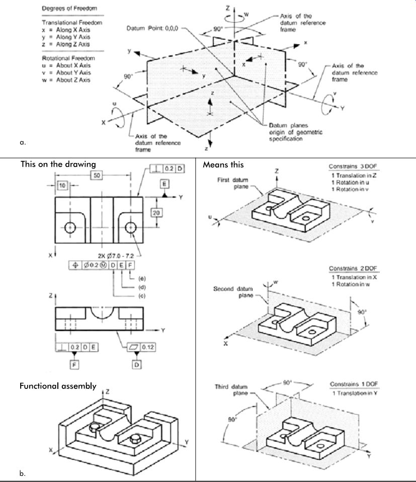
FIG. 1. (a) Datum Reference frame; (b) Sequence of datum features as they
relate to the datum Reference frame; (c) Constrained degrees of freedom for
primary datum features. (Reprinted from ASME Y14.5-2009 with permission of
the American Society of Mechanical Engineers. All rights reserved. No further
copies can be made without written permission.)
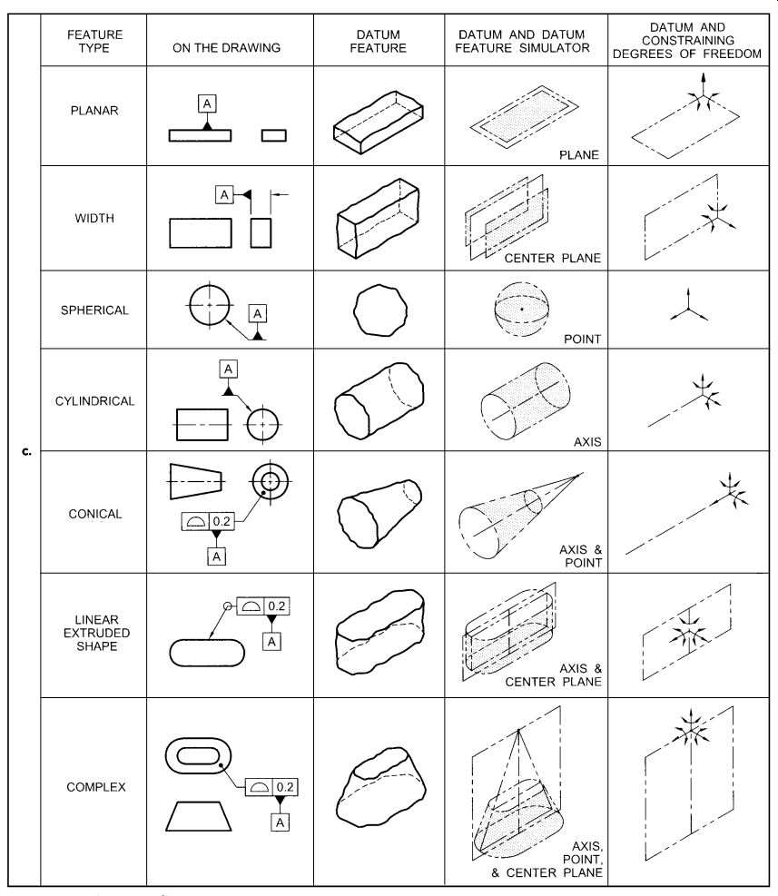
FIG. 1. (continued).
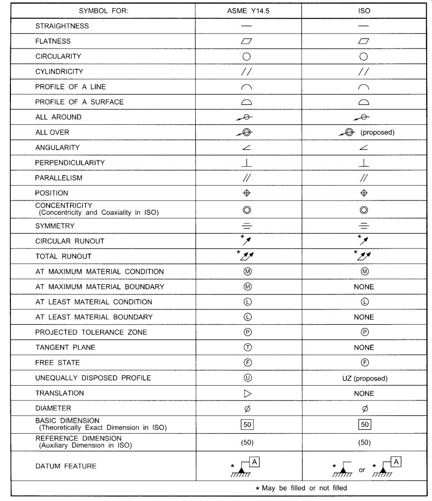
FIG. 2. Geometric characteristic symbols. (Reprinted from ASME Y14.5-2009
with permission of the American Society of Mechanical Engineers. All rights
reserved. No further copies can be made without written permission.)

FIG. 2. (continued).
Least Material Condition
Least material condition (LMC) is a modifier that, when specified on a tolerance applied to a feature of size, indicates that tolerance applies at the LMC condition of size. For example, consider the maximum diameter of a hole and the minimum diameter of a shaft. LMC is designated by the symbol l. Additional tolerance is available as the feature of size departs from the LMC to MMC. The tolerance can be verified by determining that the toleranced feature(s) does not violate the virtual condition.
Least material boundary
The least material boundary (LMB) is the limit defined by a tolerance or combination of tolerances that exists on or inside the material of a feature(s). It too is designated by the symbol l.
Projected tolerance Zone
The projected tolerance zone is used to control the angle of a hole or thread into which a pin, stud, screw, etc., will be assembled. It does this by translating the tolerance zone above the surface of the part to the maximum thickness of the mating part. A projected tolerance zone is indicated by the symbol p.
Basic dimension
Basic dimension is a theoretical value used to describe the exact size, shape, or location of a feature. A basic dimension is considered perfect.
Basic dimensions define the true position or true profile of the feature. A geometric tolerance is required to define the permissible variation from true position or true profile. A basic dimension is symbolized by boxing the dimension [10.00].
Datum feature Symbol
A datum feature symbol identifies the features that establish the relationship between the datum Reference frame and the geometric tolerance features. It is symbolized by boxing the datum letter as shown in FIG. 3. All datums identified with a datum feature symbol are also Referenced in a feature control frame. Datums Referenced in a feature control frame define the features and the sequence used to establish the datum Reference frame from which the geometric tolerance is derived.
Each feature requiring identification as the datum uses a different letter(s). To eliminate confusion, the letters I, O, and Q are not used as Reference letters. Where the alphabet is used up, double letters, such as AA, BB, ZZ, etc., are used.

FIG. 3. Datum feature symbol
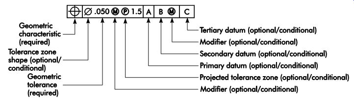
FIG. 4. Feature control frame.
Feature Control frame
The feature control frame is a boxed expression containing the geometric characteristics symbol and the form, runout, location, orientation, or profile tolerances, plus any datum References and modifiers for the feature or datum. Proper symbols and applications are shown in FIG. 4.
Datum References
Datum References follow tolerances as shown in FIGs. 4, 5 and 6. For convenience or conservation of drawing space, the feature control frame and datum feature identification symbol may be combined, as shown in FIG. 7. A common datum, such as an axis or center plane can be established from more than one feature by the use of more than one datum reference letter separated by a dash in a single feature control frame box (see FIG. 8).
Feature control frames are placed on drawings in accordance with standard ASME Y14.5-2009 drawing practices as noted in FIG. 9.
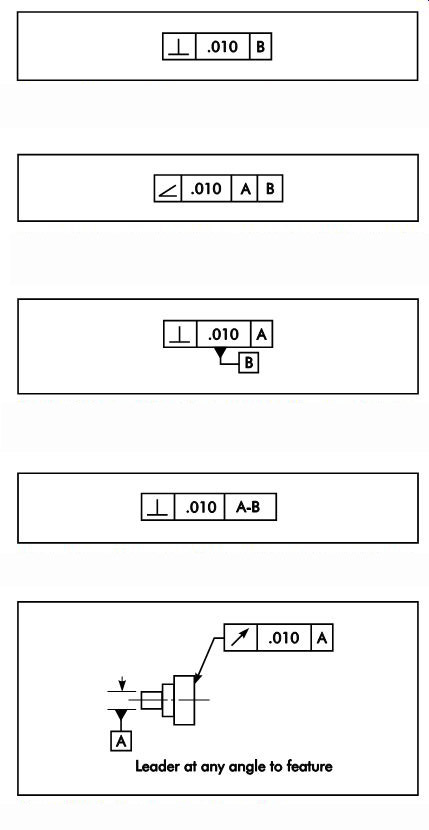
FIG. 5. Single datum Reference following the tolerance.

FIG. 6. Multiple datum References following the tolerance.

FIG. 7. Combined feature control frame and datum feature symbol.

FIG. 8. Common datum for axis or center plane.

FIG. 9. Feature control symbols.
The tolerance value shown in the feature control frame defines the allowable variation from perfect form, orientation, runout, or location of a feature. Where the specified tolerance is to indicate the diameter of a cylindrical zone or boundary, the diameter symbol, _, is placed ahead of the tolerance value in the feature control frame, as shown in FIG. 10. Otherwise the tolerance zone represents the total distance between two parallel lines, planes, the radial distance between two circles or cylinders, or geometric boundaries.
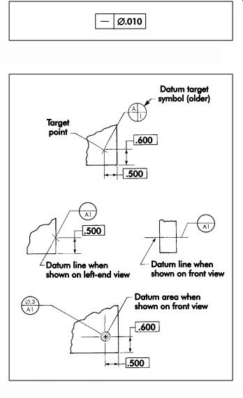
FIG. 10. Tolerance zone.
FIG. 11. Datum targets.
Datum Targets
Datum targets may be used wherever datum locations and sizes are required on castings, forgings, weldments, etc. They aid in repeat ability between manufacturing and inspection and are used to describe the elements of the fixture that contact the part for gaging. The datum target is shown with a circle divided in half.
The lower half denotes the specific datum and the upper half, when used, shows the datum size.
These symbols and their proper applications are shown in FIG. 11.
Virtual Condition
Virtual condition is a constant boundary generated by the collective effects of a size feature's specified MMC or LMC and the geometric tolerance for that material condition. Virtual condition is calculated by the following: holes (MMC - geometric tolerance = virtual condition) or (LMC + geometric tolerance = virtual condition); shafts (MMC + geometric tolerance = virtual condition) or (LMC - geometric tolerance = virtual condition). When MMC or LMC is specified, virtual condition is used to define the size and shape of the datum feature simulator or the boundary of the tolerance feature surface.
Full indicator movement
Full indicator movement (FIM) is the total indicator movement reading observed when properly applied to a part feature; it is the same as full indicator reading (FIR) and total indicator reading (TIR).
Flatness
Flatness is a condition in which all elements of a surface are in the same plane. The flatness tolerance specifies a tolerance zone bordered by two parallel planes, within which the entire surface must lie. No datum is needed or proper with a flatness tolerance. When checking flatness, all elements of the concerned surface also must be within the specified size limits, if applicable, of the part to be acceptable. An example of flatness tolerance and its meaning are shown in FIG. 12.
Straightness
Straightness is a condition where a portion of a surface or an axis is a straight line. When straightness is applied to a cylindrical feature of size, the tolerance zone specifies a cylindrical tolerance zone within which the entire axis must lie. When straightness is applied to an opposed planar feature of size, such as a tab or slot, the tolerance zone specifies a parallel plane tolerance zone within which the center plane must lie. When straightness is applied to a surface element, the tolerance zone is that between two parallel lines within which each surface element must lie. When straightness is applied to a feature of size RFS, the derived median line for an opposed planar feature of size (FOS) or the derived median line for a cylindrical FOS must be within the specified tolerance zone. When straightness is applied to a feature of size MMC or LMC, the surface of the feature must be within the virtual condition (boundary). Examples of straightness tolerances and their meanings are shown in FIG. 13. A functional gage to check a part is shown in FIG. 14.

FIG. 13. Straightness tolerance and its meaning.
Circularity (Roundness)
With respect to a cylinder or cone, circularity is having all points of the surface intersected by any plane at right angles to an axis, equal distances from the axis.
With respect to the sphere, circularity is having all points of the surface intersected by any plane passing through a common center, equal distances from that center.
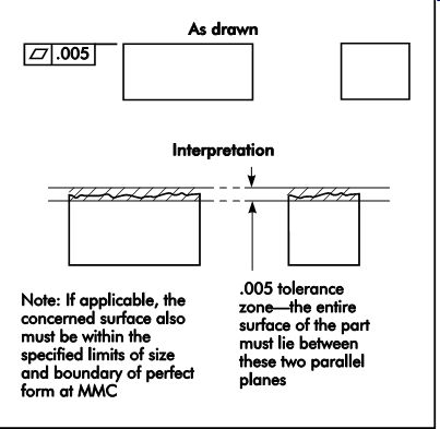
FIG. 12. Flatness tolerance and its meaning.
The circularity tolerance specifies a tolerance zone bounded by two concentric circles, within which each circular element of the surface must lie. No datum is to be specified with a circularity tolerance. When checking circularity, all elements of the surface also must be within the specified size tolerance to be acceptable. Examples of circularity tolerances and their meaning are shown in FIG. 15.
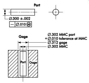
FIG. 14. Functional gage to check straightness of an axis MMC.
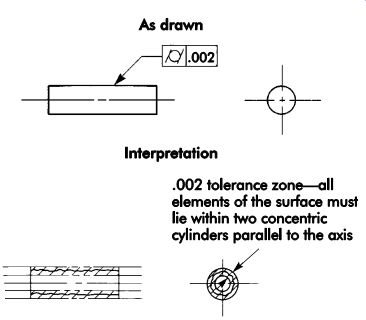
FIG. 16. Cylindricity tolerance and its meaning.
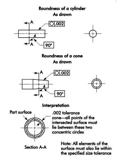
FIG. 15. Roundness tolerance and its meaning.
Cylindricity
Cylindricity is having all points on the surface of a cylinder equal distances from a common axis. Cylindricity tolerance specifies a tolerance zone bounded by two concentric cylinders, within which the surface must lie. Datum is neither needed nor proper with a cylindricity tolerance.
When checking cylindricity, all elements of the concerned surface also must be within the specified size tolerance and the boundary of perfect form at MMC. An example of a cylindricity tolerance and its meaning is shown in FIG. 16.
Profile of a line or Surface
Profile tolerancing is used to specify an allowable deviation from a desired profile. The profile tolerance specifies a uniform boundary along the desired profile within which the elements of the surface or line must lie. Datums may or may not be necessary to establish a proper relationship of the profile to mounting surfaces for assembly purposes, etc. All profiles are defined using basic dimensions. Examples of profile tolerances and their meaning are shown in FIG. 17.
Perpendicularity (Squareness)
Perpendicularity is the condition of a surface, median plane, or axis exactly 90° from a datum plane or datum axis. A perpendicularity tolerance always requires a datum, and is specified by one of the following:
• a tolerance zone bordered by two parallel planes perpendicular to a datum plane or datum axis, within which the surface or median plane of the considered feature must lie;
• a tolerance zone bordered by two parallel planes perpendicular to a datum axis, within which the axis of the considered feature must lie;
• a cylindrical tolerance zone perpendicular to a datum plane, within which the axis of the considered feature must lie, or
• a tolerance zone defined by two parallel lines perpendicular to a datum plane or datum axis, within which all elements of the surface must lie.
A perpendicularity tolerance applied to a surface also controls the flatness of the surface to the ex tent of the stated tolerance and requires the surface to be within the stated limits of size. Examples of perpendicularity tolerances and their meanings are shown in FIG. 18.
Angularity
Angularity is a condition of a surface or axis at a specified angle (other than 90°) from a datum plane or axis. A specified angularity tolerance zone is defined by two parallel planes at a specified basic angle from one or more datum plane or datum axis, within which the surface, axis, or center plane of the feature must lie. A datum is always required, and the desired angle is always shown as a basic angle. When checking angularity, all elements of the concerned feature also must be within the specified size limits of the part to be accepted. On surfaces, the angularity includes a control of flatness to the extent of the angularity tolerance. Examples of angularity tolerances and their meaning are shown in FIG. 19.
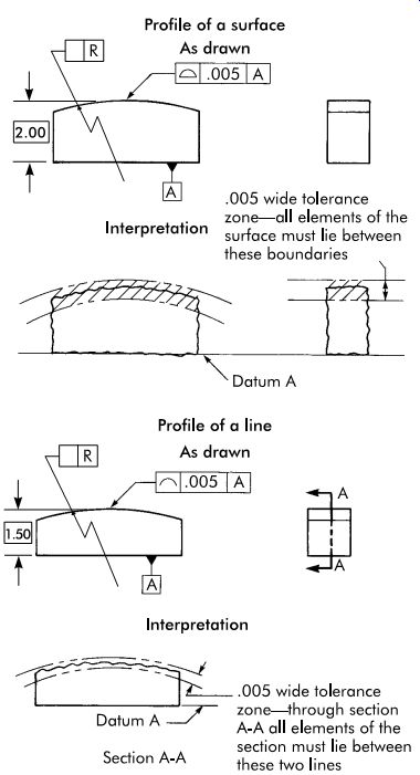
FIG. 17. Profile tolerance and its meaning.

FIG. 18. Perpendicularity tolerance and its meaning.

FIG. 19. Angularity tolerance and its meaning.
Parallelism
Parallelism is a condition of a surface, line, or axis equidistant from a datum plane or axis at all points. A parallelism tolerance always requires a datum, and can be specified by one of the following:
• a tolerance zone bounded by two parallel planes or lines parallel to a datum plane or datum axis, within which the elements of the surface or the axis of the considered feature must lie;
• a cylindrical tolerance zone whose axis is parallel to a datum axis, within which the axis of the considered feature must lie; or
• a cylindrical tolerance zone indicated by a _ preceding the tolerance value.
The parallelism tolerance applied to a surface also controls the flatness of a surface to the extent of the stated tolerance and requires the surface to be within the stated limits of size. Examples of parallelism tolerances and their meaning are shown in FIG. 20.
Runout
Runout is the deviation from the desired form of a part's surface of revolution when the part is rotated 360° around a datum axis. The runout tolerance specifies the maximum FIM allowed during the 360° rotation. Runout tolerance is always applied on an RFS basis and always re quires a datum also specified at RFS. It is used to maintain surface-to-axis control on a part (see FIG. 21).
Circular runout controls only circular elements of a surface individually and independently from one another, but total runout provides composite control of all surface elements at the same time.
When checking runout, all elements of the concerned surface must be within the specified size limits of the part to be acceptable. Examples of runout tolerances and their meaning are shown in FIG. 22.
Position
Position is a tolerance of location used to specify how far a feature of size may vary from the theoretically exact location on the part drawing.
A position tolerance defines a zone within which the axis or center plane of a feature of size can vary from this theoretically exact position. Position tolerances are applied only to size features, and datums are always required except when controlling coaxiality. A position tolerance is mainly used to maintain surface-to-surface control or axis-to-axis control on an MMC basis.
When position is applied at MMC, the surface of the feature of size must not violate the virtual condition boundary located at true position. True position tolerance theory and bonus tolerance are shown in FIG. 23.

FIG. 20. Parallelism tolerance and its meaning.
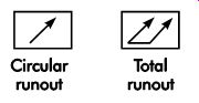
FIG. 21. Runout symbols.
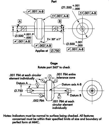
FIG. 22. Runout tolerance and its meaning.
Concentricity
Concentricity is another tolerance of location used to maintain axis-to-axis control on an RFS basis. It is a condition in which two or more features, in any combination, have a common axis.
A concentricity tolerance specifies the condition in which the median points of all diametrically opposed elements of a figure of revolution (or correspondingly located elements of two or more radially disposed features) are congruent with the axis (or center point) of a datum feature.
When checking concentricity, all elements of the concerned surfaces also must be within the specified size limits of the part to be acceptable. An example of a concentricity tolerance and its meaning is shown in FIG. 24.
Symmetry
Symmetry is another tolerance of location. It is a condition in which the median points of all opposed or correspondingly located elements of two or more feature surfaces are congruent with the axis or center plane of a datum feature. When checking symmetry, all elements of the concerned feature also must be within the specified limits of the part to be acceptable. An example of a symmetry tolerance and its meaning is shown in FIG. 25.

FIG. 23. Position tolerance theory-bonus tolerance.

FIG. 24. Concentricity-a tolerance of location and its interpretation. It
uses the center points of two elements set at opposing parallel 180° elements.
The points formed at different cross-sections must lie within the specified
tolerance zone.

FIG. 25. Symmetry-within the limits of size and RFS, all median points of
opposed elements of the slot must lie between two parallel planes 0.020 apart,
the two planes being equally disposed about datum plane B.
Three-Plane Concept
Datums are considered theoretically perfect points, axes, and planes, which are assumed to be exact for purposes of computation or reference. From that location, other features of a part may be determined. Datums are established by, or relative to, actual part features. When more than one datum feature is required on a part, it is advisable to establish a three-plane datum system consisting of three planes at right angles to each other. Where a primary datum plane is established by three points (minimum) some where on the most influential datum surface, a secondary datum plane is established by two points (minimum) on the second most influential datum surface, and a third datum plane is established by one point (minimum) on the least influential datum surface.
Where the size feature of a part, such as a cylinder or width, is used as a datum on a RFS basis, a datum axis or center plane must be established by making contact with the feature surface extremities by using precision expanding chucks, mandrels, locators, etc.
Fundamental Rules (asme y14.5-2009)
This section is reprinted from ASME Y14.5-2009 with permission of the American Society of Mechanical Engineers. All rights reserved. No further copies can be made without written permission.
General rules established by ASME Y14.5 2009 provide users of geometrics with a better understanding of the system and its proper application. Dimensioning and tolerancing shall clearly define engineering intent and conform to the following:
a. Each dimension shall have a tolerance, except for those dimensions specifically identified as Reference, maximum, mini mum, or stock (commercial stock size). The tolerance may be applied directly to the dimension (or indirectly in the case of basic dimensions), indicated by a general note, or located in a supplementary block of the drawing format. See ASME Y14.1 and ASME Y14.1M.
b. Dimensioning and tolerancing shall be complete so there is full understanding of the characteristics of each feature. Values may be expressed in an engineering drawing or in a CAD product definition data set. See ASME Y14.41. Neither scaling (measuring directly from an engineering drawing) nor assumption of a distance or size is permitted, except as follows: on undimensioned drawings, such as loft, printed wiring, templates, and master layouts prepared on stable material, provided the necessary control dimensions are specified.
c. Each necessary dimension of an end product shall be shown. No more dimensions than those necessary for complete definition shall be given. The use of Reference dimensions on a drawing should be minimized.
d. Dimensions shall be selected and arranged to suit the function and mating relationship of a part and shall not be subject to more than one interpretation.
e. The drawing should define a part without specifying manufacturing methods. Thus, only the diameter of a hole is given without indicating whether it is to be drilled, reamed, punched, or made by any other operation. However, in those instances where manufacturing, processing, quality assurance, or environmental information is essential to the definition of engineering requirements, it shall be specified on the drawing or in the document Referenced on the drawing.
f. Non-mandatory processing dimensions shall be identified by an appropriate note, such as "Non-mandatory (mfg. data)." Examples of non-mandatory data are processing dimensions that provide for finish allowance, shrink allowance, and other requirements, provided that the final dimensions are given on the drawing.
g. Dimensions should be arranged to provide required information for optimum read ability. Dimensions should be shown in true profile views and refer to visible outlines.
h. Wires, cables, sheets, rods, and other materials manufactured to gage or code numbers shall be specified by linear dimensions indicating the diameter or thickness. Gage or code numbers may be shown in parentheses following the dimension.
i. A 90° angle applies where center lines and lines depicting features are shown on a 2D orthographic drawing at right angles and no angle is specified.
j. A 90° basic angle applies where center lines of features in a pattern or surfaces shown at right angles on a 2D orthographic drawing are located or defined by basic dimensions and no angle is specified.
k. A zero basic dimension applies where axes, center planes, or surfaces are shown coincident on a drawing, and geometric tolerances establish the relationship among the features.
l. Unless otherwise specified, all dimensions and tolerances are applicable at 68° F (20° C) in accordance with ANSI/ASME B89.6.2. Compensation may be made for measurements made at other temperatures.
m. Unless otherwise specified, all dimensions and tolerances apply in a free-state condition.
n. Unless, otherwise specified, all tolerances apply for the full depth, length, and width of the feature.
o. Dimensions and tolerances apply only at the drawing level where they are specified. A dimension specified for a given feature on one level of drawing (for example, a detail drawing) is not mandatory for that feature at any other level (for example, an assembly drawing).
p. Where a coordinate system is shown on the drawing, it shall be right-handed unless otherwise specified. Each axis shall be labeled and the positive direction shall be shown.
Variations of form (Rule 1: envelope Principle) (asme y14.5-2009)
The form of an individual regular feature of size is controlled by its limits of size to the extent prescribed in the following paragraphs and as shown in FIG. 26:
a. The surface or surfaces of a regular feature of size shall not extend beyond a boundary (envelope) of perfect form at MMC. This boundary is the true geometric form represented by the drawing. No variation in form is permitted if the regular feature of size is produced at its MMC limit of size unless a straightness or flatness tolerance is associated with the size dimension or the independency symbol.
b. Where the actual local size of a regular feature of size has departed from MMC toward LMC, a local variation in form is allowed equal to the amount of such departure.
c. There is no default requirement for a boundary of perfect form at LMC. Thus, a regular feature of size produced at its LMC limit of size is permitted to vary from true form to the maximum variation allowed by the boundary of perfect form at MMC.
d. In cases where a geometric tolerance is specified to apply at LMC, perfect form at LMC is required.

FIG. 26. Rule 1.
FIG. 27. Screw threads.
FIG. 28. Positional tolerance of zero at MMC.
Form Control Does Not Apply (Exceptions to Rule 1) (ASME Y14.5-2009)
The control of geometric form prescribed by limits of size does not apply to the following:
a. stock, such as bars, sheets, tubing, structural shapes, and other items produced to established industry or government standards that prescribe limits for straightness, flatness, and other geometric characteristics. Unless geometric tolerances are specified on the drawing of a part made from these items, standards for these items govern the surfaces that remain in the as-furnished condition on the finished part.
b. parts subject to free-state variation in the unrestrained condition.
Screw threads
Each tolerance of attitude (orientation), form, runout, location, and/or datum Reference specified for a screw thread applies to the pitch diameter. For gears and splines, a qualifying notation must be added (for example, major, minor, or pitch diameter). Where an exception to this practice is necessary, a notation must be added beneath the feature control frame or datum feature symbol (FIG. 27).
Datum features of size, which are controlled by a separate tolerance or position, are noted within the same feature control frame. They apply at their virtual condition to the effect of differences in size between the applicable virtual condition of a datum feature and its MMC limit of size. When a virtual condition equal to MMC is the design requirement, a zero geometric tolerance at MMC is specified.
A virtual condition exists for a datum feature of size where its axis or center plane is controlled by a geometric tolerance. In such cases, the datum feature applies at its virtual condition even though it is Referenced in a feature control frame at MMC or LMC. When a virtual condition is equal to MMC or when LMC is the design requirement, a zero tolerance at MMC or LMC is specified. An example is illustrated in FIG. 28.
References
ASME Y14.5M-1994 (R2004). "Dimensioning and Tolerancing." New York: American Society of Mechanical Engineers.
ASME Y14.5-2009. "Dimensioning and Tolerancing: Engineering Drawing and Related Documentation Practices." New York: American Society of Mechanical Engineers.
Bibliography ANSI B4.4M-1981. "Inspection of Workpieces." Washington, D.C.: American National Standards Institute.
ANSI B4.2-1978 (R2004). "Preferred Metric Limits and Fits." Washington, D.C.: American National Standards Institute.
ANSI B89.3.1-1972 (R2003). "Measurement of Out-of-Roundness." Washington, D.C.: American National Standards Institute.
ANSI B92.1-1996. "Involute Splines and Inspection, Inch Version." Washington, D.C.: American National Standards Institute.
ANSI B92.2M-1980. "Metric Module, Involute Splines." Washington, D.C.: American National Standards Institute.
ANSI Y14.6-2001 (R2007). "Screw Thread Representation." Washington, D.C.: American National Standards Institute.
ANSI Y14.6aM-1981 (R1998). "Screw Thread Representation (Metric Supplement)." Washington, D.C.: American National Standards Institute.
ANSI/ASME B1.2 (R2007). "Gages and Gaging for Unified Inch Screw Threads." New York: American Society of Mechanical Engineers.
ANSI/ASME B89.6.2-1973 (R2003). "Tempera ture and Humidity Environment for Dimensional Measurement." New York: American Society of Mechanical Engineers.
ANSI/ASME B94.6-1984 (R2003). "Knurling." New York: American Society of Mechanical Engineers.
QUIZ

Figure A.
Figure B.
Figure C.
Figure D.
1. List 14 geometric characteristics and their U.S.A. symbols.
2. Match the terms with the appropriate leaders in Figure A.
3. What is meant by a virtual condition?
4. What is the virtual condition of the part in Figure B at MMC?
5. Name the three tolerances of location.
6. What is the virtual condition of the pin shown in Figure C at MMC?
7. Design a simple, functional gage to check the part in Figure C.
8. What is bonus tolerance?
9. Under what conditions are zero position tolerance methods used?
10. Design a simple, functional gage to check the part in Figure D.
Home PREV. NEXT Article Index top of page