AMAZON multi-meters discounts AMAZON oscilloscope discounts
1. Introduction
Approximately 97.5 percent of the water on our planet is located in the oceans and therefore is classified as seawater. Of the 2.5 percent of the planet's freshwater, approximately 70 percent is in the form of polar ice and snow and 30 percent is groundwater, river and lake water, and air moisture. So even though the volume of the earth's water is vast, less than 35 million km3 of the 1386 million km3 (8.4 million mi3 of the 333 million mi3) of water on the planet is of low salinity and is suitable for use after applying conventional water treatment only. Desalination provides a means for tapping the world's main water resource-the ocean.
Over the past 30 years, desalination has made great strides in many arid regions of the world, such as the Middle East and the Mediterranean. Technological advances and the associated decrease in water production costs over the past decade have expanded its use in areas traditionally supplied with freshwater resources.
At present, desalination plants operate in more than 120 countries worldwide; some desert states, such as Saudi Arabia and the United Arab Emirates, rely on desalinated water for over 70 percent of their water supply. According to the 2011-2012 IDA Desalination Yearbook [Global Water Intelligence (GWI) and International Desalination Association (IDA), 2012], by the end of 2011 worldwide there were approximately 16,000 desalination plants, with a total installed production capacity of 71.9 million m3/day [19,000 million gal/day (mgd)].
While currently desalination provides only 1.5 percent of the water supply worldwide, it is expected that in the next decade the construction of new desalination plants will grow exponentially due to the ever-changing climate patterns triggered by global warming combined with population growth pressures, limited availability of new and inexpensive terrestrial water sources, and dramatic advances in membrane technology, which are projected to further reduce the cost and energy use of desalination.
The brackish water quantity on the planet is fairly limited (0.5 percent), and most of the large and easily accessible brackish water aquifers worldwide are already in use. A significant portion of the new capacity growth is expected to come from the development of seawater desalination plants. While brackish water sources, especially brackish aquifers, are finite in terms of capacity and rate of recharging, the ocean has two unique and distinctive features as a water supply source--it is droughtproof and practically limitless.
Over 50 percent of the world's population lives in urban centers bordering the ocean. In many arid parts of the world, such as the Middle East, Australia, North Africa, and Southern California, the population concentration along the coast exceeds 75 percent.
Usually coastal zones are also the highest population growth hot spots. Therefore, sea water desalination provides the logical solution for a sustainable, long-term management of the growing water demand pressures in coastal areas. Brackish desalination is also expected to increase in capacity, especially in inland areas with still untapped brackish water aquifers.
A clear recent trend in seawater desalination is the construction of larger-capacity plants, which deliver an increasingly greater portion of the freshwater supply of coastal cities around the globe. While most of the large desalination plants built between 2000 and 2005 were typically designed to supply only 5 to 10 percent of the drinking water of large coastal urban centers, today most regional or national desalination project pro grams in countries such as Spain, Australia, Israel, Algeria, and Singapore aim to fill 20 to 25 percent of their long-term drinking water needs with desalinated seawater.
Increased reliance on seawater desalination is often paralleled with ongoing programs for enhanced water reuse and conservation, with a long-term target of achieving near even contributions of conventional water supply sources, seawater desalination, water reuse, and conservation to the total water portfolio of large coastal communities.
2. Terminology
The mineral or salt content of water is usually measured by the water quality parameter called total dissolved solids (TDS), the concentration of which is expressed in milligrams per liter (mg/L) or parts per thousand (ppt). The World Health Organization, as well as the United Sates Environmental Protection Agency (US EPA) under the Safe Drinking Water Act, have established a maximum TDS concentration of 500 mg/L as a potable water standard. This TDS level can be used as a classification limit to define potable (fresh) water.
Typically, water with a TDS concentration higher than 500 mg/L and not higher than 15,000 mg/L (15 ppt) is classified as brackish. Natural water sources such as sea, bay, and ocean waters that have TDS concentrations higher than 15,000 mg/L are generally classified as seawater. For example, Pacific Ocean seawater along the West Coast of the United States has an average TDS concentration of 35,000 mg/L. This concentration can actually range from 33,000 to 36,000 mg/L at various locations and depths along the coast.
3. Overview of Desalination Technologies
Sea and brackish water are typically desalinated using two general types of water treatment technologies: thermal evaporation (distillation) and reverse osmosis (RO) membrane separation.
In thermal distillation, freshwater is separated from the saline source by evaporation.
In reverse osmosis desalination, freshwater is produced from saline source water by pres sure-driven transport through semipermeable membranes. The main driving force in RO desalination is pressure, which is needed to overcome the naturally occurring osmotic pressure that in turn is proportional to the source water's salinity.
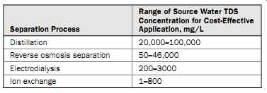
Table 1 Desalination Process Applicability
Besides thermal distillation and RO membrane separation, two other mainstream desalination technologies widely applied at present are electrodialysis (ED) and ion exchange (IX). Electrodialysis is electrically driven desalination in which salt ions are removed out of the source water through exposure to direct electric current. The main driving force for ED separation is electric current, which is proportional to the salinity of the source water.
IX is the selective removal of salt ions from water by adsorption onto ion-selective resin media. The driving force in this desalination process is the ion charge of the IX resin, which can selectively attract and retain ions of the opposite charge contained in the saline source water.
Table 1 provides a general indication of the range of source water salinity for which distillation, RO separation, ED, and IX can be applied cost effectively for desalination. For processes with overlapping salinity ranges, a life-cycle cost analysis for the site-specific conditions of a given desalination project is typically applied to determine the most suitable desalination technology for the project.
Currently, approximately 60 percent of the world's desalination systems are RO membrane separation plants and 34 percent are thermal desalination facilities. The percentage of RO desalination installations has been increasing steadily over the past 10 years due to the remarkable advances in membrane separation and energy recovery technologies, as well as the associated reductions of overall water production costs. At present, ED- and IX-based technologies contribute less than 6 percent of the total installed desalination plant capacity worldwide.
4. Thermal Desalination
4.1 Overview
All thermal desalination technologies apply distillation (i.e., are based on heating the source water) to produce water vapor, which is then condensed into a low-salinity water. Since the energy for water evaporation is practically not dependent on the source water salinity concentration, thermal evaporation is very suitable for desalination of high-salinity waters and brine. This is one of the reasons that thermal desalination has been widely adopted by Middle Eastern countries such as Saudi Arabia, Oman, Qatar, the United Arab Emirates, Bahrain, and Kuwait, which use some of the most saline water bodies on the planet for water supply (namely, the Red Sea, Persian Gulf, Gulf of Oman, and Indian Ocean). At present, approximately 75 percent of the world's thermal desalination plants are located in the Arabian Peninsula-half of those in Saudi Arabia.
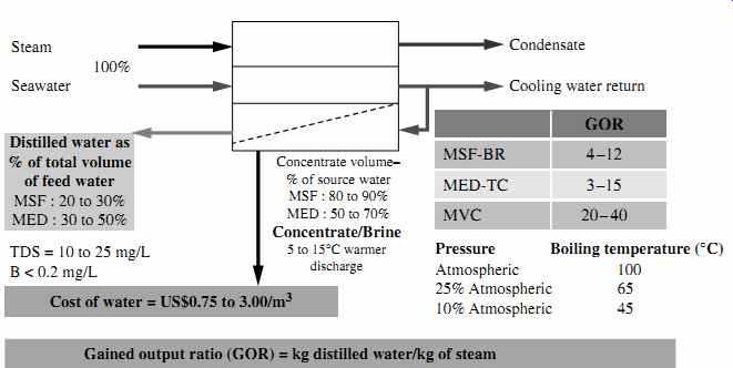
FIG. 1 General schematic of thermal evaporation technologies.
All thermal desalination plants have five key streams: source water (seawater, brackish water, or brine) used for desalination; steam needed for evaporation of the source water; cooling water to condense the freshwater vapor generated from the source water's evaporation; low salinity distilled water (distillate); and concentrate (brine), which contains the salts and other impurities separated from the source water (FIG. 1).
The three most commonly used types of thermal desalination technologies are multi stage flash distillation (MSF), multi-effect distillation (MED), and vapor compression (VC). Each of these classes of technology has evolved over the past 40 to 60 years toward improvements in efficiency and productivity. For example, MSF-BR (see FIG. 1) is the abbreviation for a multistage flash distillation process with brine recycle, which reduces the source water volume and the steam needed for evaporation. Similarly, MED-TC stands for multieffect distillation with thermal compression, a state-of-the art MED technology; and MVC is an acronym for mechanical vapor compression, a VC technology that can run without the need for an outside source of steam.
The three types of thermal technologies mainly differ by the temperature and pressure at which the source water is boiled to generate freshwater vapor. The oldest thermal evaporation process--MSF--boils water at near-atmospheric pressure and a temperature close to 100°C (212°F). This type of process requires a large quantity of high-temperature steam.
MED and VC are newer thermal desalination technologies, whose improved efficiency stems from the fact that water can be boiled at a lower temperature if the boiling process occurs at a pressure lower than the atmospheric pressure. Boiling water at a lower temperature allows the use of less and lower-quality steam for the production of the same volume of water.
As shown in FIG. 1, in MED vessels the boiling process typically occurs at lower temperatures and pressures than in MSF systems. VC thermal desalination systems operate at lower pressures than either MSF or MED, which allows these systems to evaporate water at even lower temperatures and to generate their own steam rather than depend on outside steam sources.
The ratio of the mass of low-salinity water (distillate) produced to the mass of heating steam used to produce this water is commonly referred to as the gained output ratio (GOR) or performance ratio. Depending on the thermal desalination technology used, the site-specific conditions, and the source water quality, GOR typically varies between 4 and 40--i.e., thermal desalination technologies produce 4 to 40 kg of freshwater using 1 kg of steam. The higher the GOR, the more efficient the technology, because it produces more freshwater from the same amount of steam.
As seen in FIG. 1, all thermal desalination technologies generate very low-salinity water (TDS in a range of 5 to 25 mg/L). This freshwater also has a very low content of pathogens and other contaminants of concern, such as boron, bromides, and organics.
Thermal desalination is most popular in the Middle East, where seawater desalination is typically combined with power generation that provides low-cost steam for the distillation process. Thermal desalination requires large quantities of steam.
Most power plants outside the Middle East are not designed to yield significant amounts of waste steam as a side product of power generation. This is one of the key reasons why thermal desalination has not found wider application outside of the region.
FIG. 2 Schematic of an MSF distillation system.
4.2 Multistage Flash Distillation
In the multistage flash distillation (MSF) evaporator vessels (also referred to as flash stages or effects), the high-salinity source water is heated to a temperature of 90 to 115°C (194 to 239°F) in a vessel (the heating section in FIG. 2) to create water vapor. The pres sure in the first stage is maintained slightly below the saturation vapor pressure of the water. So when the high-pressure vapor created in the heating section enters into the first stage, its pressure is reduced to a level at which the vapor "flashes" into steam.
Steam (waste heat) for the heating section is provided by the power plant co-located with the desalination plant. Each flash stage (effect) has a condenser to turn the steam into distillate. The condensers are equipped with heat exchanger tubes, which are cooled by the source water that is fed to the condensers.
Entrainment separators (mist eliminators or demister pads) remove the high-salinity mist from the low-salinity rising steam. This steam condenses into pure water (distillate)
on the heat exchanger tubes and is collected in distillate trays, from where it is conveyed to a product water tank. Distillate flows from stage to stage and is collected at the last stage.
The concentrate (brine) is generated in each stage and after collection at the last stage some of it typically is recycled to the source water stream in order to reduce the total volume of source water that must be collected by the intake for desalination. The recirculated brine flowing through the interior of the condenser tubes also removes the latent heat of condensation. As a result, the recirculated brine is also preheated close to maxi mum operating temperature, thereby recovering the energy of the condensing vapor and reducing the overall heating needs of the source water. This "brine recycle" feature has been adopted in practically all of the most recent MSF facility designs and allows significant improvement of the overall cost competitiveness of MSF installations.
Each flash stage typically produces approximately 1 percent of the total volume of the desalination plant's condensate. Since a typical MSF unit has 19 to 28 effects, the total MSF plant recovery (i.e., the volume of distillate expressed as a percentage of the total volume of processed source water) is typically 19 to 28 percent. For comparison, RO seawater desalination plants have a recovery of 40 to 45 percent. The latest MSF technology has 45-stage units--i.e., can operate at 45 percent recovery. This feature allows it to compete with RO systems in terms of recovery.
Historically, MSF was the first commercially available thermal desalination technology applied to production of potable water on a large-scale, which explains its popularity. Over 80 percent of thermally desalinated water today is produced in MSF plants.
The GOR for MSF systems is typically between 2 and 8; the latest MSF technology has a GOR of 7 to 9. The pumping power required for the operation of the MSF systems is 2.0 to 3.5 kWh/m3 (7.6 to 13.3 kWh/1000 gal) of product water.
4.3 Multiple-Effect Distillation
In multiple-effect distillation (MED) systems, saline source water is typically not heated; cold source water is sprayed via nozzles or perforated plates over bundles of heat exchanger tubes. This feed water sprayed on the tube bundles boils, and the generated vapor passes through mist eliminators, which collect brine droplets from the vapor. The feed water that turned into vapor in the first stage (effect) is introduced into the heat exchanger tubes of the next effect. Because the next effect is maintained at slightly lower pressure, although the vapor is slightly cooler, it still condenses into freshwater at this lower temperature. This process of reducing the ambient pressure in each successive stage allows the feed water to undergo multiple successive boilings without the introduction of new heat. Steam flowing through the exchanger tubes is condensed into pure water (FIG. 3) and collected from each effect. Heating steam (or vapor) introduced in the heat exchanger tubes of the first effect is provided from an outside source by a steam ejector.
The MED system shown in FIG. 3 is also equipped with a brine recycle system, which allows the introduction of warmer-than-ambient water in the first effects of the system, thereby reducing both the volume of feed water that must be collected by the plant intake system and the overall energy needs of the system.
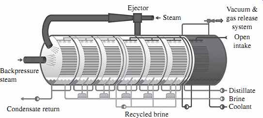
FIG. 3 Schematic of an MED system.
The main difference between the MED and MSF processes is that while vapor is created in an MSF system through flashing, evaporation of feed water in MED is achieved through heat transfer from the steam in the condenser tubes into the source water sprayed onto these tubes. This heat transfer at the same time results in condensation of the vapor to freshwater.
MED desalination systems typically operate at lower temperatures than MSF plants (maximum brine concentrate temperature of 62 to 75°C versus 115°C) and yield higher GORs. The newest MED technologies, which include vertically positioned effects (vertical tube evaporators), may yield a GOR of up to 24 kg of potable water per kilogram of steam. The pumping power required for the operation of MED systems is also lower than that typically needed for MSF plants (0.8 to 1.4 kWh/m3/3.0 to 5.3 kWh/1000 gal of product water). Therefore, MED is now increasingly gaining ground over MSF desalination, especially in the Middle East, where thermal desalination is still the predominant method for producing potable water from seawater.
4.4 Vapor Compression
The heat source for vapor compression (VC) systems is compressed vapor produced by a mechanical compressor or a steam jet ejector rather than a direct exchange of heat from steam (FIG. 4).
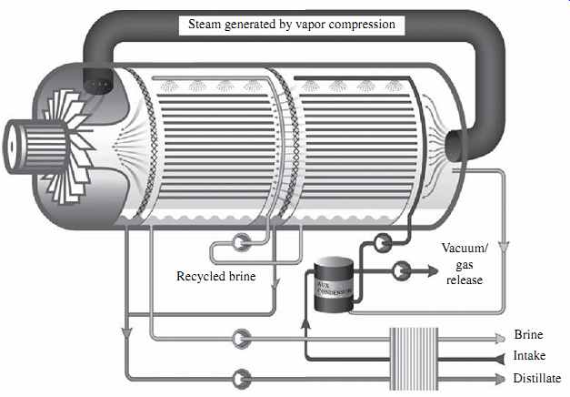
FIG. 4 Schematic of a VC system.
In VC systems the source water is evaporated and the vapor is conveyed to a compressor. The vapor is then compressed to increase its temperature to a point adequate to evaporate the source water sprayed over tube bundles through which the vapor is conveyed. As the compressed vapor exchanges its heat with the new source water being sprayed on the evaporation tubes, it is condensed into pure water. A feed water pre heater (plate-type heat exchanger) is used to start the process and reach evaporation temperature.
VC and MED work based on similar principles. However, while in MED the steam produced by source water evaporation is introduced and condensed in a separate con denser located in the downstream effect, in VC the steam generated from evaporation of new source water sprayed on the outside surface of the heat exchanger tubes is recirculated by the vapor compressor and introduced into the inner side of the of the same heat exchanger tubes in which it condenses to form distillate.
VC desalination has found applications mostly in small municipal and resort water supply systems, as well as industrial applications. The total amount of power required for the operation of mechanical VC systems is typically 8 to 12 kWh/m3 (30 to 45 kWh/ 1000 gal) of product water.
5. Membrane Desalination
5.1 Overview
Membrane desalination is the process of separating minerals from the source water using semipermeable membranes. Two general types of technologies currently used for membrane desalination are electrodialysis (ED) and RO. In ED systems, salts are separated from the source water through the application of direct current. RO is a process in which the product water (permeate) is separated from the salts contained in the source water by pressure-driven transport through a semipermeable membrane.
5.2 Electrodialysis
In electrodialysis (ED)-based desalination systems, the separation of minerals and product water is achieved through the application of direct electric current to the source water. This current drives the mineral ions and other ions with strong electric charge that are contained in the source water through ion-selective membranes to a pair of electrodes of opposite charges (FIG. 5).
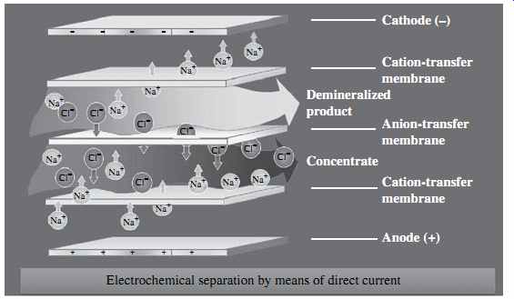
FIG. 5 Schematic of the electrodialysis process.
As ions accumulate on the surface of the electrodes, they cause fouling over time and have to be cleaned frequently in order to maintain a steady-state ED process. A practical solution to this challenge is to reverse the polarity of the oppositely charged electrodes periodically (typically two to four times per hour) in order to avoid frequent electrode cleaning. An ED process that includes periodic change of the polarity of the system's electrodes is referred to as an electrodialysis reversal (EDR) process. At present, practically all commercially available ED systems are of the EDR type.
ED systems consist of a large number (300 to 600 pairs) of cation and anion exchange membranes separated by dilute flow dividers (spacers) to keep them from sticking together and to convey the desalinated flow through and out of the membranes. Each pair of membranes is separated from the adjacent pairs above and below it by concentrate spacers which collect, convey, and evacuate the salt ions retained between the adjacent membranes.
The membranes used for ED are different from those applied for RO desalination- they have a porous structure similar to that of microfiltration and ultrafiltration membranes. RO membranes do not have physical pores. ED membranes are more resistant to chlorine and fouling and are significantly thicker than RO membranes.
It is important to note that a single set of EDR stacks can only remove approximately 50 percent of salts. As a result, multiple EDR stacks connected in series are often used to meet more stringent product water TDS targets. It should be pointed out that compared to brackish water RO membranes, which typically yield only up to 85 to 90 percent recovery, EDR systems can reach freshwater recovery of 95 percent or more.
The energy needed for ED desalination is proportional to the amount of salt removed from the source water. TDS concentration and source water quality determine to a great extent which of the two membrane separation technologies (RO or ED) is more suitable and cost effective for a given application. Typically, ED membrane separation is found to be cost competitive for source waters with TDS concentrations lower than 3000 mg/L. This applicability threshold, however, is a function of the unit cost of electricity and may vary from project to project.
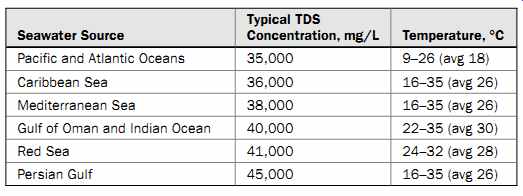
Table 2 Contaminant Removal by Alternative Desalination Technologies
The TDS removal efficiency of ED desalination systems is not affected by nonionized compounds or objects with a weak ion charge (i.e., solids particles, organics, and microorganisms). Therefore, ED membrane desalination processes can treat source waters of higher turbidity and bio-fouling and scaling potential than can RO systems.
However, the TDS removal efficiency of ED systems is typically lower than that of RO systems (15.0 to 90.0 percent versus 99.0 to 99.8 percent), which is one of the key reasons why they have found practical use mainly for brackish water desalination.
In general, EDR systems can only effectively remove particles that have a strong electric charge, such as mono- and bivalent salt ions, silica, nitrates, and radium. EDR systems have a very low removal efficiency with regard to low-charged compounds and particles--i.e., organics and pathogens. Table 2 provides a comparison of the removal efficiencies of distillation, ED, and RO systems for key source water quality compounds. One important observation from this table is that, as compared to distillation and RO separation, ED desalination only partially removes nutrients from the source water. This fact explains why EDR is often considered more attractive than RO or thermal desalination (which remove practically all minerals from the source water)
if the planned use of the desalinated water is for agricultural purposes--i.e., generating fresh or reclaimed water for irrigation of agricultural crops.
Construction and equipment costs for brackish water reverse osmosis (BWRO) and EDR systems of the same freshwater production capacity are usually comparable, or EDR is less costly, depending on the RO membrane fouling capacity of the source water.
However, since the amount of electricity consumed by EDR systems is directly proportional to the source water's salinity, at salinities of 2000 to 3000 mg/L the energy use of EDR systems usually exceeds that of BWRO or nanofiltration systems for source waters.
Therefore, EDR systems are not as commonly used as RO systems for BWRO desalination and are never applied for seawater reverse osmosis (SWRO) desalination.
It should be pointed out, however, that salinity is not the only criterion for evaluating the cost competitiveness of EDR and BWRO systems. Often, other compounds such as silica play a key role in the decision making process. For example, at the largest operational EDR plant worldwide at present-the 200,000 m3/day Barcelona desalination facility in Spain-this technology was preferred to BWRO desalination because the brackish surface water source for this plant-the Llobregat River-contains very high level of silica, which would limit recovery from a BWRO plant to only 65 percent; the EDR system can achieve 90 percent recovery. In addition, the Llobregat River was found to have very high organic content, which was projected to cause heavy fouling and operational constraints on a BWRO plant of similar size.
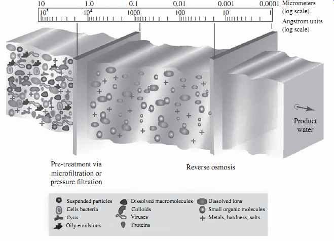
FIG. 6 Contaminant removal by RO membranes.
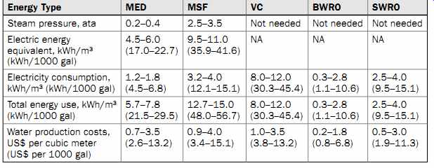
Table 3 Energy and Water Production Costs for Alternative Desalination Technologies
5.3 Reverse Osmosis
Reverse osmosis (RO) is a process where water containing inorganic salts (minerals), suspended solids, soluble and insoluble organics, aquatic microorganisms, and dissolved gases (collectively called source water constituents or contaminants) is forced under pressure through a semipermeable membrane. Semipermeable refers to a membrane that selectively allows water to pass through it at much higher rate than the transfer rate of any constituents contained in the water.
Depending on their size and electric charge, most water constituents are retained (rejected) on the feed side of the RO membrane while the purified water (permeate)
passes through the membrane. FIG. 6 illustrates the sizes and types of solids removed by RO membranes as compared to other commonly used filtration technologies.
RO membranes can reject particulate and dissolved solids of practically any size.
However, they do not reject well gases, because of their small molecular size. Usually RO membranes remove over 90 percent of compounds of 200 daltons (Da) or more. One Da is equal to 1.666054 × 10⁻²⁴g. In terms of physical size, RO membranes can reject well solids larger than 1 (Angstrom) Å. This means that they can remove practically all suspended solids, protozoa (i.e., Giardia and Cryptosporidium), bacteria, viruses, and other human pathogens contained in the source water.
While RO membranes can retain both particulate and dissolved solids, they are designed to primarily reject soluble compounds (mineral ions). The structure and configuration of RO membranes is such that they cannot store and remove from their surface large amounts of suspended solids. If left in the source water, the solid particulates would accumulate and quickly plug (foul) the surface of the RO membranes, not allowing the membranes to maintain a continuous steady-state desalination pro cess. Therefore, the suspended solids (particulates) contained in source water used for desalination have to be removed before they reach the RO membranes.
The following sections of this guide focus exclusively on the planning and engineering of RO membrane desalination systems. Over the past 20 years, RO membrane separation has evolved more rapidly than any other desalination technology, mainly because of its competitive energy consumption and water production costs (Table 3). The energy and cost analysis presented in Table 3 indicates that the all-inclusive energy consumption for freshwater production of thermal desalination plants is typically much higher than that for brackish or seawater desalination.
BWRO desalination yields the lowest overall production costs of all the desalination technologies. It is also important to note that the latest MED projects built over the last 5 years have been completed at costs comparable to those for similarly sized SWRO plants. For the majority of medium and large projects, however, SWRO desalination usually is more cost competitive than thermal desalination technologies.
6. References
Black, M., and J. King, The Atlas of Water: Mapping the World's Most Critical Resource, 2d ed., Earthscan Ltd, London, 2009.
Cotruvo, J., N. Voutchkov, J. Fawell, P. Payment, D. Cunliffe, and S. Lattemann, Desalination Technology, Health and Environmental Impacts, CRC Press and IWA Publishing, Boca Raton, FL, 2010.
Global Water Intelligence and International Desalination Association, IDA Desalination Yearbook 2011-2012, International Desalination Association and Global Water Intelligence, Oxford, UK.