Face-Lifts for Timeworn Kitchens -- part 1
| Home | Wiring | Plumbing | Kitchen/Bath |
|
You can bring an old-fashioned kitchen up to date by building on what you al ready have. Modern amenities such as soap dispensers and water filters are easy to add, as is a new countertop in a fresh color. Instead of replacing old cabinets, consider sprucing them up with new doors, drawer fronts, and matching veneer for the frames. Very often, a new floor can be installed right over the old one. Gallery of Modern Conveniences
Replacing a Pre-laminated Countertop
Installing a Sheet-Vinyl Floor
The Versatility of Vinyl Tiles
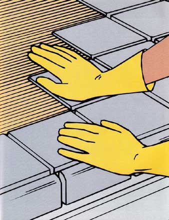
Laying a ceramic-tile countertop A Safer Electrical ReceptacleSince the mid-1970s, the National Electrical Code has required that any electrical receptacle that is installed within 6 feet of a sink must be protected by a ground-fault circuit interrupter, or GFCI. This device detects the smallest leakage of electrical current—called a ground fault—and turns off power in the receptacle within second. Replacing an old receptacle with a new GFCI is economical insurance. Because one GFCI protects all receptacles that are downstream from it on the same circuit, you can install the device anywhere on the kitchen circuit between the service panel and the receptacles that re quire this protection. For a GFCI to function, the wires must be properly connected to the terminals labeled “line” and “load.” Reversing these connections will still allow electricity to flow through the receptacle, but it will render the GFCI protection inoperative. Before Proceeding: Some jurisdictions require a permit for any work on a house’s electrical wiring and an inspection once it’s completed. Also check your house for aluminum wiring; it’s dull gray in color, some times coated with copper. The code allows only specially licensed electricians to work on it. If you have any doubts, consult an electrician. OUTGOING WIRES CAUTION---First, trip the circuit breaker or unscrew the fuse in the service panel that protects the receptacle’s circuit. Then remove the cover plate and set a multitester for 250 volts AC. Touch one probe to the green grounding screw and the other in turn to each silver- and brass-colored screw. Repeat the test at the 10-volt AC setting. Any reading other than 0 volts indicates that there is a problem in the circuit; call an electrician. 1. Wiring the GFCI. 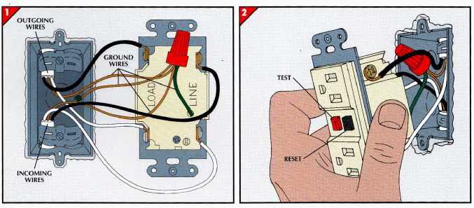
• With the power off, remove the receptacle and disconnect the bottom set of black and white wires. Plug a radio into the receptacle and turn the power back on; if the radio is silent, you have disconnected the incoming wires. • Turn off power at the service panel. Attach incoming wires to the “line” side of the GFCI, black to the brass- colored screw post and white to the silver-colored post. Connect outgoing wires to the “load” side of the GFCI, black to brass and white to silver. Attach a short length of bare copper wire to the box’s green screw post. Use a wire cap to join this wire with all other green or bare cop per wires in the box and the GFCI ( above). • Some GFC have wire leads instead of screws. Proceed as instructed above, but match wires by color and connect them with wire caps. 2. Mounting the GFCI. (above right) • Tuck the wires back into the electrical box, then secure the GFCI receptacle to the box with the mounting screws and replace the cover plate. • Turn on power at the service panel and test the GFCI and any protected receptacles between it and the end of the circuit. To do so, plug a radio into each receptacle in turn and push the test button on the GFCI. If in each case the reset button pops out and the radio goes silent, all is well. If the radio does not go off, or if you cannot push the reset button to restore power, turn off power at the service panel and check the wiring of the GFCI. • If the wiring is correct and the problem persists, either the GFCI is faulty or there is a problem elsewhere. If re placing the GFCI doesn’t work, call an electrician. ++++++++++++++++++++++++++++++ Gallery of Modern Conveniences Soap and hot water at your finger tips, pure water for drinking and cooking, a seemingly endless supply of ice, and bright, glare-free light on a kitchen countertop—any of these add to the efficiency and convenience of a kitchen. Soap and Hot Water: A soap dispenser and a tap that delivers near- boiling water are usually mounted to a stainless steel sink through a hole cut in the back rim of the sink with a knockout punch. Piercing the rim of a cast-iron or porcelain sink is impracticable, but either device may be installed in the countertop, provided the soap dispenser or waterspout is long enough to reach the basin. Installing a hot-water tap re quires not only the existence of a new, GFCI-protected receptacle for an uninterrupted flow of electricity; but also the proximity of a cold-water line that can be tapped. For this purpose, use a saddle valve, an ingenious, virtually foolproof device for drawing water from copper or plastic pipe. Buy a valve that fits your supply pipes and the flexible tubing for the tap. Clean Water: Under-the-counter water filters fit into the cold-water line supplying the kitchen sink. The replaceable cartridges in some filters trap sediment, particulate matter, and unpleasant tastes found in water, while others remove lead, chemicals, and bacteria. Ice on Tap: Almost all models of refrigerators made since the early 1970s allow for the installation of an icemaker, usually obtained from the manufacturer as a kit. The icemaker must be connected to a cold-water-supply pipe by 0.25-inch copper tubing. Use a saddle valve to tap into a water pipe convenient for routing the tubing to the back of the refrigerator. Under-Cabinet Lighting: A fluorescent light mounted under a cabinet provides bright, glare-free illumination for a countertop or sink. Home-improvement stores sell ready-to-install lighting that can be plugged into any handy receptacle. TOOLS:
MATERIALS:
MOUNTING A SOAP DISPENSER AT THE SINK 1. Drilling a starter hole. 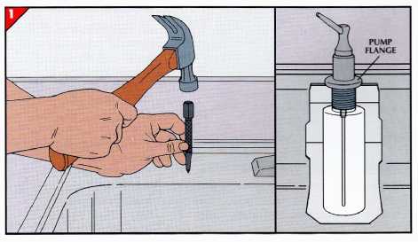
• Pick a location on the back rim of the sink where there is sufficient space underneath for the soap reservoir. • Mark a point on the rim so that the pump flange ( far right) rests fully on metal and does not overhang the sink or extend over the countertop. Dimple the rim at that point with a center punch or nail set ( right). • Drill a starter hole at the dimple with a 1/8-inch bit. Then widen the hole to 7/16-inch with increasingly larger bits. 2. Finishing the hole. 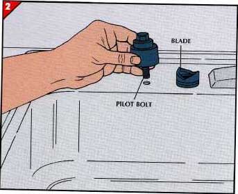
• Insert the pilot bolt of a knockout punch into the starter hole from the top. From beneath the sink, screw the bladed part of the tool onto the bolt hand tight. • Turn the bolt with a wrench until the blade cuts through the stainless steel. To avoid bruised knuckles as the punch breaks through, never push the wrench handle away from you; instead, always pull it toward you. 3. Installing the dispenser. 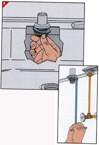
• Apply a thin bead of plumber’s putty to the underside of the pump flange. • Insert the shank of the pump assembly into the hole, and secure it with the washer and nut supplied with the kit. With a basin wrench, tighten the nut a quarter turn beyond finger tight. Wipe away any excess putty around the flange. • Fill the reservoir with soap. Screw it onto the shank of the hand pump beneath the sink. 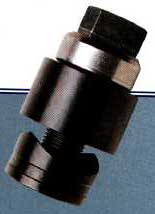
THE KNOCKOUT PUNCH---This ingenious tool cuts precise holes in stainless steel quickly and easily. A bolt, passed through a pilot hole drilled in the metal, connects the top and bottom halves of the punch. Turning the bolt head at the top pulls the bottom—with its finely honed cutting edge—upward through the steel. Most tool-rental stores carry a selection of knockout punches in diameters from 0.5 inch to as large as 4.5 inches, usually in 1/8-inch increments. FILTERED WATER FOR THE KITCHEN TAP 1. Attaching the mounting bracket. 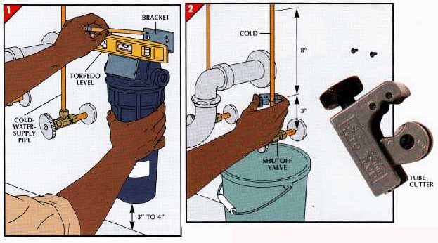
• Place the filter housing on the mounting bracket. Choose a location for the bracket to the right of the cold-water-supply pipe leading to the faucet. Also allow 3 to 4 inches above the floor for clearance when changing filter cartridges. • Hold the bracket level against the wall, and mark the holes for mounting screws. • Set the bracket aside, and drive the screws into the back of the cabinet, leaving about inch of each screw exposed. 2. Attaching the fittings. (above right) • Close the cold-water shutoff valve, then mark the cold- water pipe 3 inches above the valve and 8 inches above that mark. • Place a bucket below the pipe to catch drips, then cut out the piece of pipe between the marks with a tube cutter or hacksaw. • Smooth the pipe edges on both sides of the gap with an emery board, and clean out the cut ends with a pipe reamer. Then slip one of the dual compression fittings that come with the filter kit over each end of the cut pipe. To avoid damaging the compression rings, tighten each fitting only one turn past hand tight with an adjustable wrench. • Working in a clockwise direction, wrap two layers of plumbing tape around the threads of the fittings that screw into the in and out ports of the filter housing. Screw the fittings into the ports, and tighten one turn past hand tight. 3. Hooking up the filter. 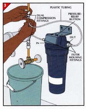
• Shorten the flexible plastic tubes so that they reach from the dual compression fittings on the pipe to the in and out ports of the filter without being either too long or so short that they curve sharply. • Insert a length of plastic tubing in the dual fitting coming from the shutoff valve, and connect it to the threaded fitting occupying the in port of the filter housing. Fasten another tube to the fitting in the out port, and connect it to the upper dual fitting on the pipe. • Hang the bracket on the mounting screws and tighten them. Open the cold-water shut off valve and press the pressure- relief button on the filter to re lease air displaced as water enters. Tighten any leaky fittings by a quarter turn until the seep age stops. • Run cold water from the tap for 2 or 3 minutes, both to saturate the filter cartridge and to flush out loose material. WATER AT A NEAR BOIL 1. Mounting the tap and tank. 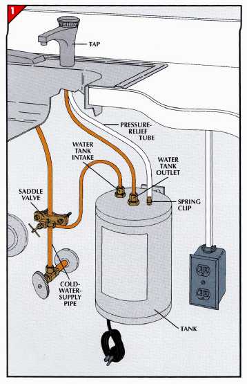
• Choose a location for the tap on the sink rim where the spout will over hang the sink. Then cut a hole in the rim with a knockout punch as shown. • Lay a thin bead of plumber’s putty around the tap’s flange, or use the gasket supplied with some kits. Insert the shank of the tap in the hole. Secure it with the washer and lock nut sup plied with the unit, and tighten gently with a basin wrench. Some models use bolts and a metal brace to hold the tap from the underside of the sink rim. • Below the sink, level the mounting bracket for the water heater tank, and screw it to the inside cabinet wall as close as possible to the cold-water- supply pipe. Mount the tank onto the bracket. 2. Tapping a water line. 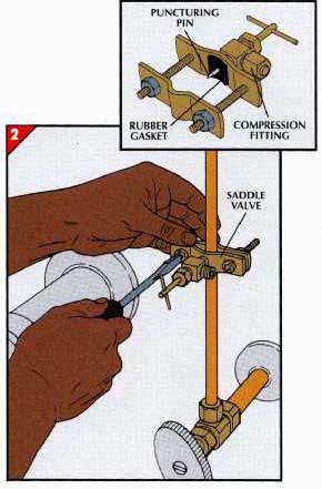
• Close the shutoff valve to the cold-water-supply pipe. • Turn the handle of the saddle valve counterclockwise until the puncturing pin is fully recessed beneath the rubber gasket. • Join the two pieces of the valve around the pipe, and draw them together snugly with the nuts and bolts provided. • Insert a length of flexible cop per tubing into the compression fitting of the saddle valve. To avoid damaging the compression ring inside it, turn the nut one turn past hand tight. • Use a compression fitting to fasten the tubing to the water-tank intake. Use copper tubing and compression fittings to connect the tank’s outlet port to the underside of the tap. • Attach the pressure-relief tube, which is connected to the tap at the factory, to the small brass nipple at the top of the tank, and se cure it with the spring clip sup plied with the kit. • Open the cold-water shutoff. Turn the handle of the saddle valve clockwise until the pin punctures the pipe, then open the valve to adjust water flow. Check for leaks, and tighten fit tings as needed. CAUTION ---The water tank gets hot; rags or flammable substances should not be stored in the same cabinet. 3. Wiring a new receptacle. 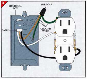
• Extend a 20-amp circuit to a convenient spot below the sink, and install a surface-mounted electrical box there for the new receptacle. If the circuit is not protected by a GFCI, install one. • Connect the black wire in the cable to one of the brass-colored screws on the receptacle and the white wire to a silver-colored screw. Cut short ground wires for the receptacle and the box, and join them with a wire cap to the bare wire in the cable as shown (left). • Push the receptacle into the box, and secure it with the screws provided. Then install the cover plate. • Plug in the water heater. AN ICEMAKER FOR THE FREEZER 1. Mounting the icemaker. 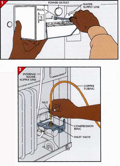
• Unplug the refrigerator and pull it away from the wall. • Inside the freezer, lift out the removable back panel to expose the end of the internal water- supply line. • Remove the covers from the mounting holes and the power outlet in the freezer wall. Plug in the icemaker, then screw it into the mounting holes so that the supply line overhangs the water basin on the icemaker. 2. Hooking up a water line. • Locate the most convenient cold-water-supply line and close its shutoff valve. • Tap into the line with a saddle valve. Attach flexible copper tubing to the valve’s compression fitting, and run it to the back of the refrigerator. Cut the tubing about 12 inches longer than necessary to reach the water inlet valve. • Slip a compression ring and nut onto the tubing, and insert it in the inlet valve for the icemaker’s internal water-supply line. The valve can be found at the back of the refrigerator, usually near the floor. • Plug in the refrigerator, turn on the water at the shutoff valve, and open the saddle valve. Check all connections for leaks, and tighten them if necessary. • Adjust the water fill lever and icemaker shutoff arm as described. UNDER-CABINET LIGHTING 1. Mounting the housing. 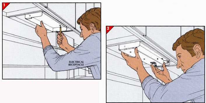
• Where you choose to install the under-cabinet lighting is a matter of personal taste. The closer it’s to the front edge of the cabinet, the more direct light you get on the countertop work area. If it’s mounted farther back, the unit itself is hid den from view, but you also get less direct light on the work area. • Hold the housing against the underside of a cabinet and mark the bracket holes, then drill pi lot holes inch deep for the mounting screws. • Attach the fixture housing to the cabinet with wood screws no longer than inch. 2. Attaching the light. • Take the fluorescent bulb out of the light fix ture to avoid breaking it as you work. • Secure the fixture to the housing. Some models screw to the housing, others slip into support brackets. 3. Hiding the cord. 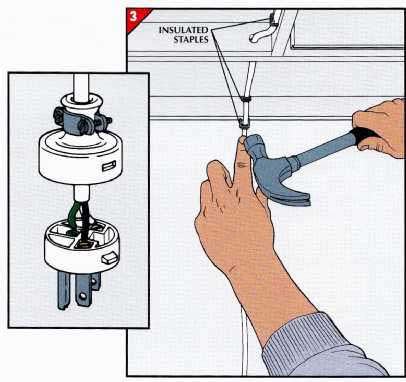
• Run the fixture’s cord under the cabinet frame to the nearest grounded wall outlet. Anchor the cord with insulated wire staples every 4 to 6 inches. • To overcome an obstacle such as an adjacent cabinet frame, drill a hole through the frame large enough for the cord to pass but not the plug. • If the cord is attached to a plug with screw terminals, take the plug apart, thread the cord through the hole, then reattach the plug. Snip off a molded plug with wire-cutters and at tach a new grounded plug to the end of the cord. • Install the fluorescent bulb and plug the unit in. ++++++++++++++++++++++++++++++++ Replacing a Pre-laminated Countertop Replacing an old laminated countertop with a new one can make a quick and dramatic change in the appearance of your kitchen. Aside from the cutting of an opening for the sink, the job consists mostly of simple steps— drilling holes, driving screws, hooking up the sink—and can usually be completed in a single day. Critical Measurements: The most important element in a smooth installation is the precise measurement of the existing countertop. Check your results carefully, and take them, along with a sketch of the counter layout, to the supplier, who will provide the replacement. Choosing a Style: Available in a wide variety of laminate colors and patterns, countertops also come in two styles: custom self-edge and post-form. The difference lies in the treatment of the front edge and of the joint between the work surface and the backsplash, the short vertical surface that catches overflows and spills at the counter’s rear. In a custom self-edge counter- top, the work surface and the back- splash meet in a sharp 90-degree angle. The front edge is also perpendicular to the work surface. Custom self-edge is the style to choose if you wish to finish the edge with wood trim called bullnose. A post-form counter has a gently rounded front edge and backsplash joint, with the laminate curving smoothly over them. For the neatest job whichever style you choose, specify that the countertop ends, even those that abut a wall or appliance, be covered with laminate. TOOLS:
MATERIALS:
- - - - - - - Taking the measurements. 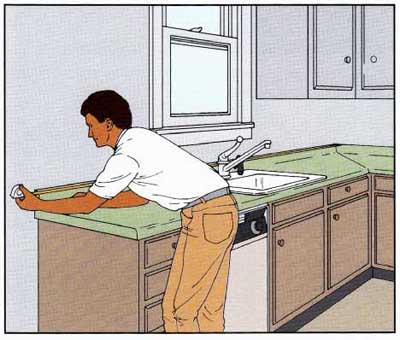
• First, measure the length of the countertop. For an L-shaped counter (left), hook the end of a tape measure over the backsplash and measure the length of each leg of the old countertop. • Check the distance from the back of the backsplash to the front edge. If the distance differs from the standard 25 inches, specify the actual measurement when ordering the replacement. PREPARING THE WAY 1. Removing the sink. 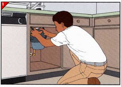
• Turn off the water supply to the faucet. Open the faucet to drain the supply lines, then disconnect them from the faucet with a basin wrench. Use the same tool to remove the dishwasher air gap. • Cut power to the dishwasher and garbage disposer at the service panel. Disconnect drain and dishwasher plumbing from the disposer, then detach it from the sink, either by turning it to unlock it or by loosening mounting screws under the sink. Set the disposer on the cabinet floor. • Unscrew the anchors under the counter- top that hold the sink. Separate the counter- top and the sink edge with a utility knife, then lift out the sink and set it aside. 2. Making a sink template. 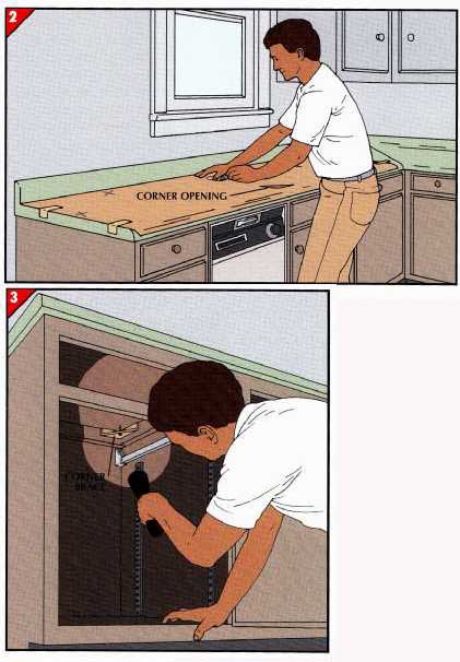
• Cut a sheet of paper long enough to extend from one end of the countertop past the sink cutout. Tape the paper even with the end of the countertop and with one edge against the backsplash. Mark these edges of the paper (Xs). • Using the corners of the sink cutout as guides, cut through the paper with a utility knife to make an opening at each corner. 3. Removing the old countertop. • Using a flashlight to illuminate the dark corners, examine cabinet corner braces for screws in the underside of the countertop. Remove any screws you find and save them for securing the new countertop. • Remove the screws that secure the dish washer to the underside of the countertop. • If the space between the backsplash and the wall is filled with caulk, cut the caulk away with a utility knife. • With a helper, lift the old countertop from the cabinets. INSTALLING THE NEW COUNTERTOP 1. Marking a sink cutout. 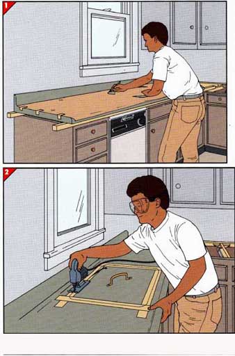
• Cut 2-by-2s to support the new countertop when marking and cutting the sink opening. With a helper, set the countertop on the supports. • Tape the template to the countertop using the marks that were made earlier to position it. • With a marker, transfer the corners cut into the template to the countertop. Remove the template and join the corners with the marker and a straightedge. • Cover the resulting outline of the sink cutout with strips of 2-inch-wide masking tape to protect the laminate when you saw it. If the cutting line is not visible through the tape, remove the tape and darken the line, then re place the tape. 2. Cutting the sink opening. • Screw a handle to the countertop in the center of the cutout, then drill a 1-inch-diameter hole inside the cutout area, near a corner. • Fit a blade suitable for cutting laminate into a saber saw. Start the saw with the blade in the hole and cut to ward the line, then along it. • As you approach the end of the cut, grasp the handle to prevent the waste piece from sagging, which might split the laminate. 3. Positioning the countertop. 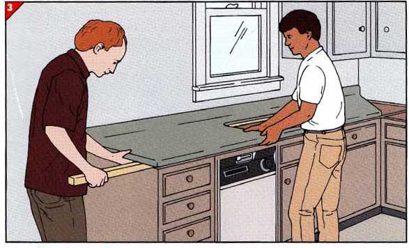
• While you lift the countertop slightly at the sink cutout, have a helper slide out the front 2-by-2 support, followed by the rear support. • For an L-shaped cabinet, lift the other countertop section onto the cabinet to help align both pieces while you finish installing the first one. • Set the sink in the cutout, adjusting sink and countertop so that the sink drain aligns with the drainpipe in the wall and the backsplash fits against the wall. 4. Caulking the sink. 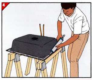
• Pencil a line perpendicular to the front edge of the sink and continue it onto the countertop to mark the sink position. Draw a similar line at one edge of the sink, then remove the sink and Support it upside down above the floor. • Clean any old caulk from the underside of the sink, then apply a thin bead of caulk around the outer edge of the sink lip (above). • Apply a i-inch-thick bead of caulk to the countertop around the edge of the sink cutout. 5. Reinstalling the sink. 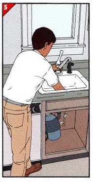
• To avoid disturbing the fresh caulk, lift the sink by the base of the faucet and the drain hole. • Set the sink into the cutout, aligning the pencil marks on the sink edges with those on the countertop. • Reconnect all plumbing detached during removal of the sink. • Screw in the anchors that hold the sink in place, drilling pilot holes for the screws if necessary. • Wipe excess caulk from around the sink edge with a rag dampened with de natured alcohol. 6. Securing the countertop. 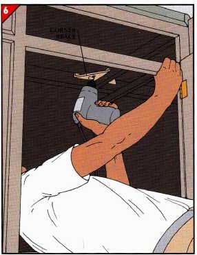
• To bore pilot holes for the anchoring screws from the old countertop, use a drill bit slightly narrower than the screws. Prevent the bit from going all the way through the countertop by wrapping the bit with tape. Place the tape at a distance from the drill tip equal to the screw length less 1/8-inch. • Drill pilot holes through the existing holes in the cabinet corner braces as shown at left. (Pilot holes need not be vertical.) Screw the countertop in place. • Screw the dishwasher to the under side of the countertop. 7. Completing an L-shaped countertop. 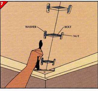 • Slide the unfastened section along the cabinet and apply a thin bead of caulk to the mitered edge. Then slip the sections together again. • Insert a corner fastener—a bolt with a rectangular nut and washer—in each of the channels precut at the joint. With a helper to hold the countertop sections flush with each other, tighten the fasteners with a wrench, back to front. Wipe excess caulk from the joint. • Screw the countertop to the cabinet. 8. Caulking the backsplash. 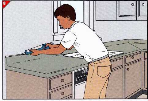
To prevent water seepage between the countertop and the wall, fill the gap between the top of the back- splash and the wall with a bead of caulk. It’s not necessary to seal the ends of the backsplash. ++++++++++++++++++++++++++ A Ceramic Tile Countertop Durable glazed tile is virtually impossible to scratch, stain, or scorch, and the shiny, nonporous finish provides a sanitary work surface. Standard 4.5-inch-square tiles and latex-based grout both come in a wide variety of colors. Buying Tile: First, calculate the square footage of your countertop, then add 10 percent to allow for wastage when cutting tiles and in case you ever need a replacement. Measure the countertop edge to determine how many trim tiles you’ll need, and note your requirements for special tiles—mitered pieces for inside corners and caps for outside corners. The top row of the backsplash requires bullnose tiles, including a pair of double bullnose units for the ends. The Layout: The most appealing design will satisfy three goals: uniform grout joints, a symmetrical arrangement around the sink, and no tiles less than 1 inch wide— they are hard to cut and unsightly. Make a dry run using plastic spacers or the molded-in tabs on some tiles to provide 1/8-inch grout joints. If that approach fails, try the suggestions below. You can make all the necessary cuts yourself to fit tiles around the sink and against the wall. The trim tiles, however, must be cut by a tile supplier. Preparing the Countertop: Remove the sink, as shown, and the old backsplash. If re moving the backsplash is impracticable, you can tile over it. Fill any nicks or cracks in the countertop with wood putty, then sand it with coarse (60-grit) sandpaper. Tithe counter overhangs the base cabinets, either glue and nail strips of wood to the underside to make the edge as deep as the trim tile, or cut off the overhang with a circular saw; set the blade to the thickness of the countertop and ad just the saw guide to cut it flush with the edge of the cabinets. TOOLS:
MATERIALS:
SAFETY TIPS --- Rubber gloves protect your hands when you are mixing and applying tile adhesive, grout, and sealant. Wear safety goggles when cutting tile to shield your eyes from flying chips. LAYING OUT A DRY RUN 1. Marking the trim-tile line. 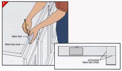
• Starting at one end of the counter, set a trim tile against the edge, with its lip on the counter- top. Hold a pencil against the lip, and slide the pencil and tile together along the edge to mark a trim-tile line. • On an L-shaped counter, use a framing square to extend the penciled trim-tile lines from the inside corner back to the wall or backsplash. EXTENDED TRIM-TILE LINES 2. Laying a dry run. 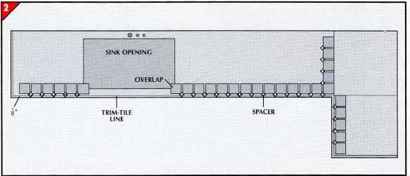
• Place two rows of tiles on the countertop, one of them inch—the width of a spacer tab—behind the trim-tile line, the other at right angles to the first and continuing to the wall. On a straight countertop, position the first tile inch inside the trim-tile line at the end of the countertop. For an L-shaped counter, begin at the extended trim-tile line in the corner. • Where a tile protrudes over the sink opening, measure the overlap and match it when positioning the first tile at the opposite side of the opening. Continue the dry run to within a tile width of the end of the countertop. Repeat the procedure for the other arm of an L-shaped unit. • Place tiles along the front of the sink opening, working from the corners toward the center. • Examine the dry run, if it requires tiles less than 1 inch wide to fit around the sink opening or to fill any gaps, widen the tile spacing. 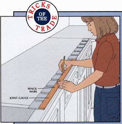
----TRICKS of the TRADE ---- Adjusting the Layout One way to fix a dry run that calls for tiles less than 1 inch wide is to spread the tiles farther apart—the joints can be up to 0.25 inch wide. If this approach fails, try marking the centerline of the sink opening on the countertop. Then center either a tile or a grout joint on the mark and work outward to the corners. Should neither of these tactics solve the problem, you may have to settle for an asymmetrical arrangement of tiles around the sink. Spacers are of no help in achieving uniform grout joints if they are wider than 1/8-inch. Instead, make a joint gauge from a 3-foot piece of 0.25-inch wood lath. Without disturbing the dry run, lay the lath flush with a tile edge and mark its edge at the corners of several tiles. Use this gauge to position tiles on the countertop, left to right and front to rear. 3. Working around the sink. 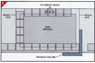
• Remove the tile next to the one overlapping each corner of the sink opening, and lay a framing square against the cabinet face as shown at right. Pencil a line on both sides of the opening from the front of the counter to the wall. • Set a row of tiles along these lines, using spacers or the joint gauge to keep the joints uniform, then lay a row of tiles behind the opening flush against the wall. 4. Marking the tiles for cutting. 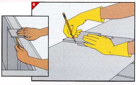
• Wherever tiles extend over the sink opening, mark a cutting line on the underside by drawing the pencil along the edge of the opening. At the back of the opening, mark tiles to fit between the wall and plumbing holes in the countertop. • For a row of partial tiles against the wall, place a tile facedown on top of a full tile in the preceding row, edge against the wall. Mark both sides of the overlapping tile one joint width from the edge of the underlying tile, then join these marks across the face of the tile. TWO TECHNIQUES FOR CUTTING TILE A tabletop tile cutter. 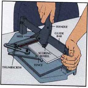
• Set a marked tile on the padded base, lift the handle, and push it forward until the scoring wheel touches the tile’s far edge. • Then place the wheel on the cutting line, set the adjustable fence against the side of the tile, and tighten the thumbscrew. The fence helps hold the tile and simplifies cutting several tiles to the same width. • Pulling up on the handle, slide it toward you to score the tile. • To break the tile, rest the heel on the tile and press firmly on the handle. CAUTION----Cut tiles are sharp. Dull the edges with a tile sander, available from any tile supplier. Irregular cuts with tile flippers. 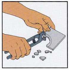
• Position the jaws of the flippers to take a 1/8-inch bite from the edge of the tile, then squeeze the handles to flip off a small piece of tile. • Continue taking 1/8-inch bites until you reach the cutting line. 1. Setting the trim tiles. 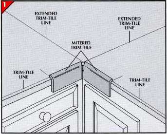
• For an L-shaped counter, make two marks at the countertop edge, each a tile width from one of the extended trim-tile lines. • Using a notched trowel, spread epoxy-based adhesive on both inside surfaces of a mitered- corner trim tile. Align the tile with the marks and the trim-tile line at the L’s inside corner, and press the tile firmly in place without sliding it along the surface. Repeat for the other corner trim tile, then, using spacers or a joint gauge, proceed to both ends of the counter. Stick caps to outside corners, then continue to the walls with trim tiles. • On a straight counter, start the row of trim with an outside corner cap—or with the tile at one end of a countertop that is set between walls or cabinets. 2. Spreading the adhesive. 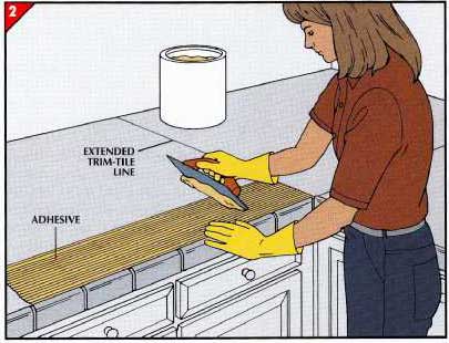
• Starting at one end of a straight counter or the inside corner of an L shaped counter, spread a band of adhesive one tile wide about 24 inches along the countertop. • On a straight counter, start in one corner and align the edges of a square tile with a trim tile. Press it down firmly without sliding it across the adhesive. On an L-shaped counter, align a square tile with the mitered trim tile and the extended trim-tile line. • Then set a row of tiles along the entire band of adhesive. 3. Laying surface tiles. 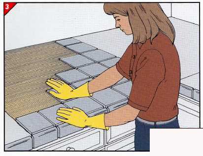
• Spread adhesive between the first row of tiles and the wall. Working from the edge of the countertop to ward the wall, set a row of tiles along the edge of a straight counter or the extended trim-tile line of an L-shaped counter (left). • Continue to set tiles in diagonal rows until all the adhesive is covered. 4. Tamping the tiles. 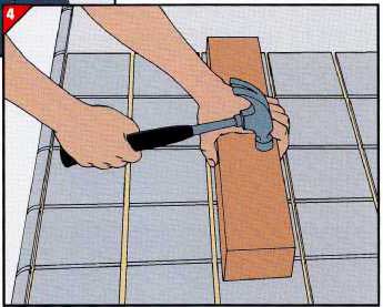
• Level the tiles you have laid so far with a straight 2-by-4 about 18 inches long. Place the board facedown on the tiles and move it around, gently tap ping it with a hammer to force protruding tiles into the adhesive. Wipe away excess adhesive with a solvent recommended by the manufacturer. • Finish tiling the countertop, a section at a time. 5. Making a backsplash. 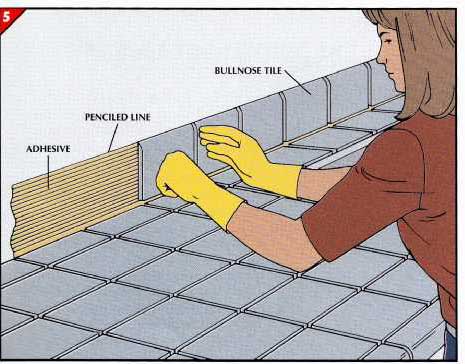
• Mark the height of a bullnose tile on the wall at several points. Add the width of a grout joint to this mark, and draw a pencil line across the wall at this level. • Spread a band of adhesive 24 inches along the wall between the countertop tiles and the pencil line. Set bull- nose tiles into the adhesive, each with the curved edge at the line and the sides aligned with the corresponding tile on the countertop. Continue setting tiles along the length of the back- splash. At each end of the backsplash, set a double-bullnose tile—one with two rounded edges. • Let the adhesive cure for 24 hours. =TILING AN EXIXTING BACKSPLASH= 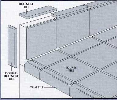
Most laminate countertops have built-in back- splashes, typically ¾-inch thick and 4 inches high. If the backsplash cannot be detached easily, you can tile it to match the countertop. The front face is covered with regular square tiles; measure and cut them two joint widths shorter than the backsplash height. In addition, cut two tiles to leave one joint width uncovered at the ends of the backsplash. Cover the top of the backsplash with bullnose tiles, cut so that the rounded front edges are even with the faces of the vertical tiles. On the rectangular end of the backsplash, use a double-bullnose tile—rounded on two adjacent sides—with the rounded edges even with the top and front of the backsplash. 6. Grouting the counter and backsplash. 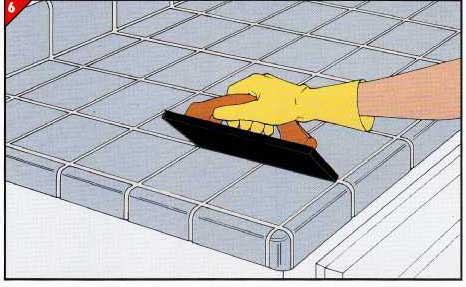
• Press twisted strips of newspaper into the joint between countertop and backsplash tiles to prevent grout from entering. • Scoop grout onto the tiles, 1 cup at a time. Sweep the edge of a rubber-faced float diagonally across the surface several times to force the grout into the joints. • Compact the grout in each joint with the edge of the float so that the grout is slightly below the surface of the tiles. • When all joints are filled, clean the float and sweep it across the tiles like a squeegee to remove excess grout. Wipe the surface with a damp sponge, and let it dry. Polish off any grout haze with a soft cloth. Caulk the joint between the countertop and the backsplash. • Let the grout cure for three days, then spray the joints with a silicone-based sealer to prevent stains and leaks. |
| HOME | Prev: Custom Solutions for Storage Problems -- part 2 | Next: | Article Index |