Making Deep Cabinets Accessible
The back part of a deep cabinet is often hard to reach and difficult
to see, making it less than ideal for storage. To open up this space,
you can build movable storage units that pivot on hinges or roll out
on drawer glides. Tailored to fit your cabinet, these units can provide
more accessible space for anything from canned goods to kitchen utensils.
A Swing-Out Shelf Unit: Pivoting on a hinge at one side to allow access
to the back of the cabinet, this unit has shelves on front and back
sized for standard jars and cans. The weight of its contents demands
solid support, which you can pro vide by attaching its mounting cleat
with screws long enough to penetrate into the side of an adjoining
cabinet. To avoid excessive stress on the mounting hardware, don’t
load a swing-out unit with heavy items such as large juice cans.
Dual Bins: Side-by-side glide-out bins, with partitions and shelves
that fit your needs, are more complicated to build but accommodate
awkward items. In the examples, one bin has a rear compartment for
long-handled skillets and a front one for saucepans with space below
for lids. The other bin combines shelves with a compartment for tall
items and a top tray for large cutlery and other utensils.
Planning: The dimensions of the swing-out and glide-out units shown
depend on the size of the original cabinets and your storage needs.
The arrangement you choose may include shelves for cans and jars, trays
for flatware, or compartments for tall items that are hard to store
in conventional cabinets and drawers. In determining the number and
spacing of shelves, allow at least 1 extra inch between shelves, to
facilitate storing and removing objects.
If your existing cabinets have permanent shelves, you may need to
cut them back or remove them entirely before installing a new storage
unit.
Materials: Most of the parts of the units shown here are made of clear
birch plywood, which has smooth surfaces that are easily prepared for
painting or staining. The vertical pieces, which carry most of the
structural loads, are made from 0.75-inch plywood, as are the shelves
for the swing-out unit. Shelves and rails for the dual bins are cut
from 0.5-inch sheets, and the broad panel that closes one side of a
glide-out bin is made from lighter 0.25-inch plywood. Cleats that support
hinges or drawer glides are 1-by-2 clear pine.
Building Tips: When cutting ply wood, use a circular saw with a ply
wood blade or a combination blade that makes both crosscuts and rip
cuts. To insure the proper alignment of joints in the dual bins, cut
the pieces with dadoes, rabbets, and cutouts first. Make the remaining
pieces as you go along. For both units, hold pieces together with bar
clamps while you drill pilot holes for inconspicuous trim-head screws.
Protect the unit’s finish with scrap wood under the clamp. Test assemblies
for fit and alignment before gluing.
TOOLS:
- Bar clamps
- Tape measure
- 0.25-inch or 3/8-inch power drill
- Circular saw
- Saber saw
- Hacksaw
- Metal file
- Router
- Level
- Framing square
MATERIALS:
- 3/4, 1/2-, and ¼ inch clear birch plywood
- 0.25-inch wood lattice
- 1 -by-2s for cleats
- Carpenter’s glue
- Sandpaper (medium grit)
- Shims
- Drawer-glide assemblies
- 1 5/8-inch trimhead screws
- No. 6 finishing nails
- No. 8 flathead screws
- 1 -inch wire brads
- 1.5-inch piano hinge
- Magnetic catch
CONSTRUCTING SWING-OUT SHELVES
1. Determining the dimensions.
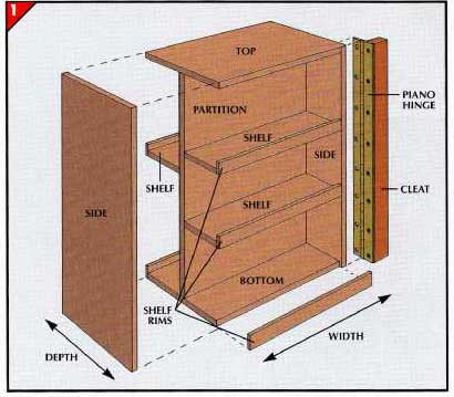
A swing-out shelf unit (disassembled at right) is made of 0.75-inch
birch plywood, with shelf rims of 0.25-inch lattice. The pieces are
held together by glue and 1 5/8-inch trim-head screws.
• The height of the unit is 1 to 1.5 inches less than the height of
the cabinet opening. To ensure swinging clearance, make the width of
the unit narrower than the cabinet opening by a third of the unit’s
depth.
• The unit’s total depth is the sum of the shelf depths plus the thickness
of the partition and shelf rims. In the example shown here, with 3.75”
shelves for standard-size cans, the depth is 8.75 inches.
2. Assembling the sides and partition.
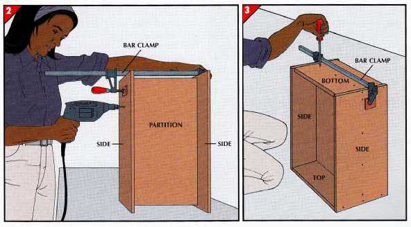
• Cut two sides from 0.75-inch plywood to the planned height and depth
of the unit. Cut the partition 1.5 inches shorter and narrower than
the height and width.
• Clamp the partition between the sides so that it’s centered top
to bottom as well as front to back.
• Mark the thickness of the partition on the top edge of each side.
Use the marks as guides for pilot holes for 1 trim-head screws at 6-
to 8- inch intervals through each side.
3. Adding the top and bottom. (above right)
• Cut top and bottom pieces 1.5 inches shorter than the width of the
unit. Match the top piece to the unit’s total depth, and make the bottom
piece 0.5-inch narrower to accommodate shelf rims.
• Slide the top into position atop the partition; clamp the sides
against it. Drill pilot holes for 1 5/8-inch trim-head screws to attach
the top piece to the partition and side pieces. Screw the top in place.
• Turn the unit upside down and attach the bottom piece in the same
way, centering it between the sides to leave room for rims.
4. Installing the shelves.

• Cut shelves as long as the width of the partition and 0.25 inch
narrower than the distance from the partition to the front edge of
the side, to leave space for shelf rims.
• Position a shelf between the sides, making sure it’s level, and
clamp the sides to hold it.
• Drill two pilot holes through each side into the shelf, placing
one about an inch from the front edge of the shelf and the other an
inch from the partition, and secure the shelf with 1 5/8-inch trim-head
screws.
• Install the remaining shelves 0.25-inch lattice, as long as the
shelf. Apply glue to the front edge of the shelves, and nail the rims
flush with the shelf bottoms with 1 -inch wire brads (inset).
FINISHING AND INSTALLING THE UNIT
1. Cutting the cabinet shelf.
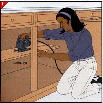
• On each permanent shelf in the cabinet, mark a cutting line parallel
to the front edge and as far from the inside of the cabinet frame as
the depth of the swing-out unit plus 1 inch. Start the line 1 inch
from the same side of the cabinet as the unit’s hinge, and make the
line several inches longer than the width of the unit, in order to
al low swinging clearance. Check these measurements by holding the
unit inside the cabinet against the shelf.
• Use a saber saw or a handsaw to cut the shelf along the line. Smooth
the cut edges with medium-grit sandpaper.
2. Attaching the hinge to the unit.

• Position the hinge at the front edge of the pivot side. Center it
vertically between the top and bottom and align the hinge barrel with
the edge.
3. Mounting the unit in the cabinet. (above right)
• Cut a 1 -by-2 cleat to the height of the cabinet wall on the pivot
side. Attach the cleat to the back of the cabinet frame (inset) with
1 trimhead screws driven every 6 to 8 inches through the cleat into
the frame.
• Drive 3-inch trimhead screws through the side of the cleat and into
the cabinet’s side wall, at intervals that avoid the screws that are
already in place.
• Set the unit on shims inside the cabinet and check for swinging
clearance at the top.
• Position the free hinge leaf on the cleat with the barrel against
the cleat’s back edge. Mark the hinge holes on the cleat.
• Drill pilot holes and use 2-inch No. 4 or No. 5 screws (the largest
that will seat flush against the hinge to secure the hinge to the
cleat .
4. Installing the magnetic catch.

• Screw the steel strike plate of the catch to the inner bottom corner
of the unit on the side away from the hinge. Be sure the edges of the
plate are flush with the edges of the corner.
• Swing the unit inside the cabinet and position the magnetic catch
on the cabinet floor against the strike plate.
• Mark the position of screw holes on the cabinet floor, swing the
unit out, and use the screws provided with the catch to secure it.
DUAL BINS FOR CONVENIENT STORAGE
Determining the dimensions.
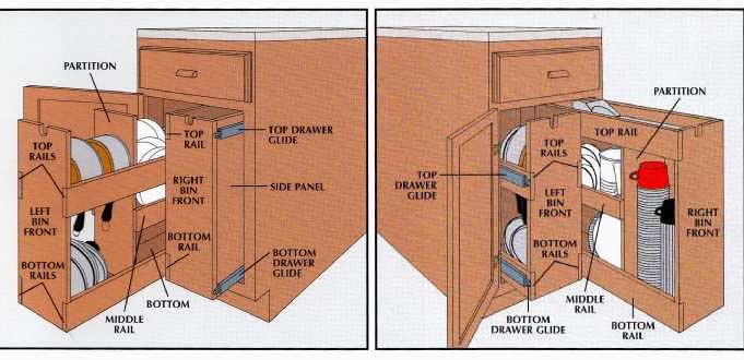
The overall dimensions of glide-out bins allow clearance for sliding
and closing the door. The bins are at least 1 inch shorter than the
height of the opening and 2.5 inches narrower than the width. The depth
is 0.25 inch less than the distance from the back of the cabinet to
the inside edge of the front frame. Individual parts, including the
width of each bin, are sized according to use. The bins are made of
clear birch plywood: 0.75-inch for the fronts, backs, and partitions;
0.25-inch for the side panel, and 0.5-inch for other parts.
CUTTING THE MAJOR PIECES
Grooved right bin components.
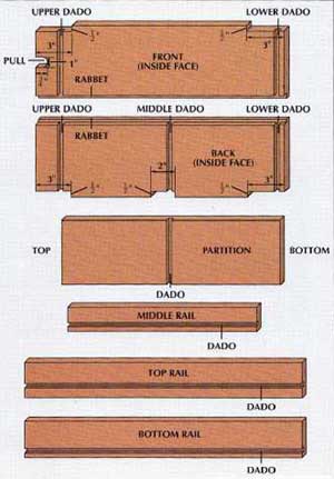
Start by making the front, back, and partition, as well as the rails.
• The front and back are as high and wide as the bin; the partition
is 3.25 inches shorter and 0.75-inch narrower. The 3-inch-wide top
and bottom rails are as long as the unit’s depth; the length of the
2-inch-wide middle rail is determined by the position of the partition
(Step 24).
• A routed notch 1 inch wide and 0.75-inch deep at the top front serves
as a pull. Corner cutouts sawed in the front and back are 3-inches-by
0.5-inch; a middle cutout in the back is 2 inches wide.
• Dadoes 0.5-inch wide and 0.25-inch deep across the top of the front
and back and in the top rail form a continuous groove after assembly;
so do dadoes at the bottom of the front and back and in the bottom
rail. A dado 0.25-inch from the bottom of the middle cutout aligns
with dadoes across the partition and in the middle rail. A rabbet 0.25-inch
wide and 0.25-inch deep on the right edge of the front and back fits
the side panel.
Grooved left bin components.
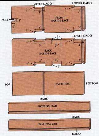
As with the right bin, make the front, back, and partition. Cut the
bottom rails, but make the top and middle rails once the partition
is in place.
• The front and back are the planned height and width of the bin,
and the partition is 0.5-inch shorter and 1 inch narrower. Two 3-inch-wide
bottom rails are as long as the unit’s depth.
• The upper cutouts on the front and back are positioned to allow
room for planned storage, as are the middle cutouts on the back. The
up per and bottom corner cutouts are 3 inches by 0.5 inch, and the
middle cutout is 2 inches by 0.5 inch.
• A notch routed at the top front serves as a pull. A 0.5-inch-wide
dado cut 0.25-inch deep across the front is inch from the bottom of
the upper cutout; the partition’s dado aligns with it. The lower dadoes
on the front and back are inch above the bottom, as are the dadoes
running the length of the bottom rails.
STRAIGH CUTS WITH A ROUTER:
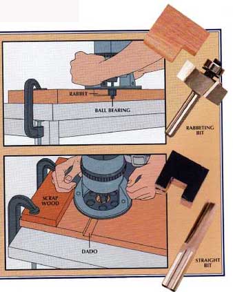
A router makes fast work of the precise cuts crucial to cabinet joints.
The variety of avail able bits and the router’s adjustable cutting
depth allow cuts of almost any size or shape. A rabbeting bit (photograph,
far right) which cuts a notch on the edge of a board, usually has a
ball-bearing guide on its tip that rides along the edge, keeping the
cut at a uniform width. A straight bit (photograph, bottom right),
which makes a square-bottom groove or dado, has no such guide. To ensure
straight cuts, clamp a perfectly straight board to the workpiece, parallel
to the cutting line and at a distance that allows the bit to just cut
the line. Hold the router firmly against the guide when cutting. For
either type of cut, grip the router with both hands and move it against
the resistance of the cutting.
CAUTION---Always wear goggles when routing, and never start the router
with the bit in contact with the workpiece.
ASSEMBLING THE RIGHT BIN
1. Building the frame.
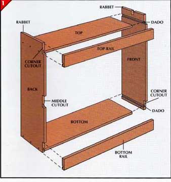
• Cut top and bottom pieces from 0.5-inch ply wood, 1 inch shorter
than the depth of the cabinet and 0.5-inch narrower than the front
and back.
• Apply glue to both ends of the top and bottom and slip them into
the dadoes on the front and back, positioned so that one edge extends
0.25-inch into the cutouts while the other edge is flush with the inner
face of the rabbets.
• Clamp the pieces together, and drill three pilot holes through the
front and back into the top and bottom. Secure these joints with trim-head
screws.
• When the glue has set, remove the clamps. Apply glue to the long
edges of the top and bottom and slip the dadoes of the top and bottom
rails over the edges. Drill pilot holes through the rail ends into
the edges of the front and back panels and through the rails into the
edges of the top and bottom. Secure the rails with trim-head screws.
2. Constructing the middle shelf.

• Cut a shelf from 0.5-inch plywood, 0.25 inch wider than the partition
and 0.5 inch longer than the distance from the back to the planned
partition location.
• Apply glue to one end of the shelf and slip it into the dado on
the partition so that the shelf edge on the open side extends 0.25-inch
beyond the partition. Drill pilot holes and secure the joint with trimhead
screws through the partition into the shelf.
• When the glue is dry, apply glue to the other end of the shelf and
to the top and bottom of the partition, and position the assembly in
the bin with one side of the shelf extending 0.25-inch into the middle
cutout, and the other side flush with the inner face of the rabbets.
Complete the joints with screws through the back, top, bottom, and
rails.
• Glue and screw the middle rail to the protruding edge of the shelf.
3. Attaching the side panel and sliding channels.
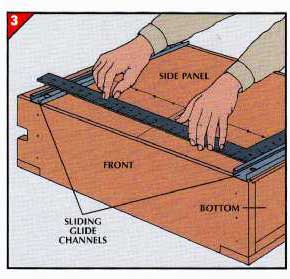
• Cut the side panel from 0.25-inch plywood, to fit snugly within
the rabbets.
• Position the panel in the rabbets and use a pencil to outline the
edges of the top, bottom, shelf, and partition on the panel. Transfer
the outlines to the other side of the panel, and reposition it with
these marks facing up.
• Place the glide channels on the panel, with their front ends flush
with the front of the bin and their mounting screw holes centered over
the outlines of the top and bottom. Mark the screw holes.
• Glue the side panel to the bin and secure it with No. 6 finishing
nails countersunk along all the outlines, taking care to avoid the
marked screw positions.
• Align the top sliding channel with the screw hole markings, and
attach it with the screws pro vided, driven through the panel into
the top.
• Position the bottom sliding channel over its markings and use a
framing square to make sure the distance between the top and bottom
channels is equal at both ends, then secure the channel with screws
through the side panel into the bottom.
4. Positioning the bin.
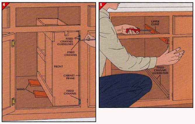
• Slip the fixed glide channels over the sliding channels on the bin.
Position the bin in the cabinet on shims so it’s level and clears the
top and side of the opening.
• Mark the locations of the upper and lower fixed channels on the
edge of the cabinet frame .
• Measure the distance between the fixed channels and the cabinet
wall. Use 1 -by-2 clear pine to make two mounting cleats of that thickness
and as long as the cabinet depth.
5. Installing the bin. (above right)
• Extend lines from the marks on the cabinet edge along the sides
and 1 inch onto the back of the cabinet.
• Position a fixed channel against a cleat, flush with the front edge,
and drill mounting holes in the cleat.
• Center a cleat on the upper guidelines, and avoiding the mounting
holes, drill four pilot holes through the cleat into the side wall.
Attach the cleat with No. 8 screws.
• Mount the lower cleat the same way.
• Screw the fixed channels to the cleats using longer screws than
those provided, for added strength.
• Install the bin by inserting the sliding channels into the cabinet-mounted
fixed channels.
ASSEMBLING THE LEFT BIN
1. Making the bottom.
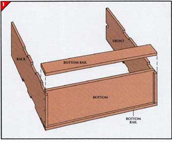
• Cut a bottom piece 1 inch shorter than the depth of the cabinet,
and - inch narrower than the front and back.
• Apply glue to the ends of the bottom piece and slip it into the
lower dadoes on the front and back, with its edges extending inch into
the cut outs on both sides. Clamp the bottom in place, drill pilot
holes into its edge through the front and back, and secure it with
trim-head screws.
• Apply glue to the edges of the bottom, then attach the two bottom
rails with screws into the bottom on the front and back.
2. Building the long supports.
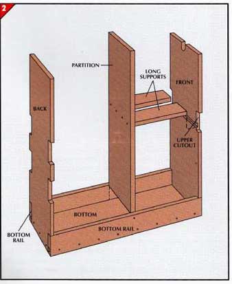
• Cut long supports from 0.5-inch plywood to the length corresponding
to the planned position of the partition, adding 0.5 inch to allow
for the dadoes. Make each support wide enough to leave a gap between
them for pot handles when their outer edges are flush with the edge
of the partition.
• Apply glue to one end of each sup port and slip them into the partition
dado, outer edges flush with the edges of the partition. Clamp the
pieces together, drill pilot holes through the partition, and secure
the pieces with trimhead screws.
• Apply glue to the free ends of the supports and the bottom of the
partition, then set the assembly in the bin with the supports fitted
firmly into the front dado.
• Secure the assembly with screws through the front, bottom, and rails.
BOTTOM RAIL
3. Constructing the top and middle rails.
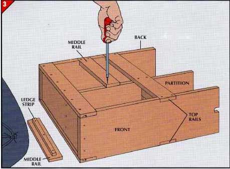
• Make two top rails with the same dimensions as the bottom rails.
Glue and screw them into the upper cutouts on the front and back.
• Make two middle rails 2.5 inches wide and as long as the distance
from the outside of the back piece to the front side of the partition.
• Cut two ledge strips, 1.5 inches shorter than the middle rails and
0.75 inch wide, and center one on each middle rail. Secure them with
glue and trim head screws.
• With the ledge strips facing inward, glue and screw the middle rails
to the partition and the middle cutouts on the back.
4. Completing the left bin.
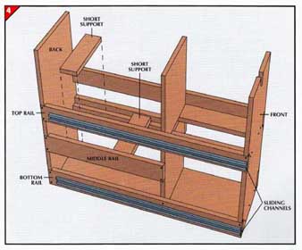
• Make two short supports as long as the distance between the inside
edges of the middle rails. Their width can vary, but they must be wide
enough to support the smallest item you plan to store.
• Lower the short supports onto the ledge strips and leave them loose
or glue them.
• Attach the sliding channels to the lop and bottom rails of the bin,
centered and flush with the front, and mount the bin in the cabinet.
SLIDING CHANNELS
An Island That Rolls
NOTE: We use both fractional and decimal dimensions interchangeably
(so, 0.25 inch = ¼-inch; 0.5 inch = ½-inch; etc.)
Four swivel casters and a butcher- block top can transform a pair
of kitchen cabinets into a movable island. With the cabinets fastened
back to back, this unit offers additional storage space with adjustable
shelves and doors on opposite sides, plus an extra work surface that
goes where you need it.
Buy two preassembled wall cabinets, 12 inches deep and anywhere from
18 to 60 inches wide, depending on your needs and the size of your
kitchen. To make the island the same height as your counter- top—typically
36 inches—choose cabinets 30 inches high; the swivel casters and butcher-block
top will add the rest. The top should over hang the cabinets on all
four sides by 3 inches, providing handholds for rolling the island.
Select cabinets with tops and bottoms of plywood or particle board
at least 0.5 inch thick and add solid wood rein forcing boards to support
the casters and butcher block.
If the joint where the two cabinets fit together is noticeable, fill
it with wood putty or conceal it under 1.25 by 0.25-inch wood lath,
fastened with carpenter’s glue and countersunk brads.
TOOLS:
- 3/8-inch power drill
- Circular saw
- Awl
- Medium-size flat-blade screwdriver
- Adjustable wrench
MATERIALS:
- Two matching kitchen wall cabinets
- Laminated maple butcher block, at least 1.75 inches thick
- Four 1 -by-8 pine or fir boards Four flat-plate locking swivel
casters, with 2 wheels and 75-lb. load capacity rating
- Six 1/4- by 3-inch stove bolts, each with 1 nut, 2 flat washers,
and 1 split lock washer
- Eight No. 8 1k-inch round- head wood screws
- Sixteen No. 8 1 1/4-inch round- head wood screws
- Six No. 10, 3/4-inch round-head wood screws, each with 1 flat washer
JOINING TWO CABINETS
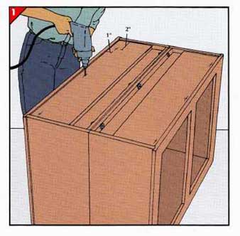
1. Drilling holes for bolts.
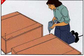
• Remove the doors and shelves from the cabinets and lay them facedown,
tops facing each other and sides flush.
• With a pencil, mark 0.5 inch down from the top edge and 2 inches
in from each side of the cabinets. Make a third mark halfway between.
• Make sure the marks on both cabinets align with each other, then
turn the cabinets around and repeat along the bottoms.
• Drill 0.25-inch holes through the lip of the recessed area at each
mark.
2. Bolting cabinets together.
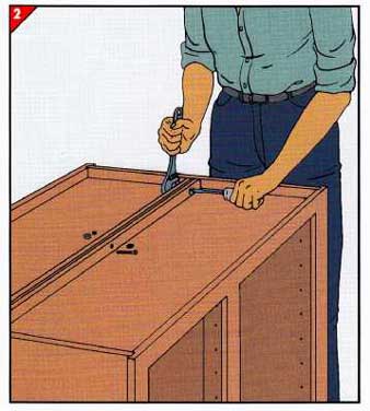
• Set the cabinets upright, back to back, and push an awl through
each pair of holes to align them. Slide flat washers onto three stove
bolts, and push each bolt through the holes in both cabinets. Put a
flat washer and a split washer on each bolt, followed by a nut; then
turn each nut finger tight.
• Turn the cabinets over by tipping them on their sides, not on a
front panel. Bolt the bottom edges together the same way as the top.
After all six bolts are in place, hold each bolthead with a screwdriver
and tighten the nut with a wrench until the split lock washer is compressed.
3. Fitting the reinforcement boards.
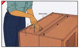
•Measure the length of the recessed area on the cabinet tops and bottoms
and cut four pieces of 1-by-8 to that length.
• Make four marks on each board, 3 inches from the ends and 1 inch
from the edges, and drill 3/32-inch holes at each mark.
• Set a board in one of the cabinet recesses, snug against the front
edge of the cabinet. Insert an awl into each hole in the board and
push the point firmly into the cabinet . Remove the board, and drill
a 3/32-inch hole through the cabinet at each awl mark. Repeat the process
for each reinforcement board in each of the remaining three recesses.
4. Fastening the boards to the cabinets.
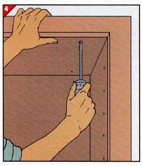
• Set one of the reinforcement boards into its cabinet recess and
push the awl through the holes to align them.
• Then, reach inside the cabinet and drive a 1.25-inch No. 8 wood
screw through each hole in the cabinet and up into the board. Install
the remaining reinforcement boards the same way.
5. Attaching the casters.
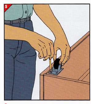
• Turn the cabinets bottom side up. Set a caster in each corner with
the holes in the mounting plate at least 0.5 inch from the edges of
the reinforcement board. Mark the board through the holes in the plate.
• With a 3/32-inch bit, drill 3/32-inch-deep pilot holes at each mark.
Fasten the casters to the board with 0.75-inch No. 8 wood screws.
• Unfinished cabinets—including the doors and shelves—should be painted
or stained before proceeding to the next step.
MOUNTING A BUTCHER-BLOCK TOP
1. Drilling through cabinet roof.
• Turn the cabinets upright again, then measure and mark 2 inches
in from each side and 1 inch back from the front edge of the reinforcement
boards. Center a third mark between these two.
• Drill 0.25-inch holes through the reinforcement boards and the cabinet
tops at each mark.
2. Marking the butcher block.
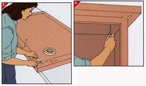
Set the butcher block upside down and, with a straightedge, draw a
line 3 inches in from and parallel to each edge. Affix two pieces of
masking tape at each corner as shown above, aligning the inner edges
of the tape with the lines.
3. Positioning the butcher block. (above right)
• Set the butcher block on the cabinets, aligning the tape strips
with the cabinet corners. Push an awl through each hole in the cabinet
roof to mark the underside of the butcher block.
• Remove the butcher block and turn it over. Then, with a 1/8-inch
bit, drill 0.5-inch-deep pilot holes at each mark.
4. Attaching the butcher block.

• Reposition the butcher block on the cabinet. With the awl, align
the holes in the cabinet roof with those in the block.
• Slip flat washers onto six 3-inch No. 10 wood screws, and drive
the screws part way into the block. When all the screws are in place,
go back and tighten each one completely.
• Remove the masking tape. Replace the shelves and re-hang the doors.
|