Introduction to Simple Structures
The choice of a foundation from among the possibilities described in Section 1 is generally based on such purely objective considerations as the requirements of a building code, or the lay of the land, or the depth of the frost line. Choosing a cabin to build on the foundation is a more personal matter. Esthetic preferences and personal life styles enter into the decision, and your first thoughts may be flights of fancy—perhaps a sophisticated chalet with an expanse of picture- window glass, or a forest retreat with a deck cantilevered over a lake. In the end, however, you are likely to turn to one of the four cabin types shown. All can be built by an amateur with a minimum of special skills and tools. Each will suit a particular taste or solve a special construction problem.
The most common vacation cabin—and in fact the most common residential style in North America—is a frame structure with a skeleton of conventional stud walls. The design is especially adapted to the needs of a builder who lives so far from his building site that regular evening or weekend work on the site is impractical. Working at his own pace, whenever time is available, he assembles framing modules at home and sheathes them in plywood, with precut openings for doors and windows. The completed modules are trucked to the site and fitted together in a single day.
For a builder working on the site, the easiest cabin to assemble is the A-frame. Instead of framing a set of walls, putting in floor joists, then topping the structure with a roof, the builder assembles a set of huge triangles that combine the framing for walls, roof and floor in one. The triangles can be built on the ground with a minimum of joinery, then tilted into place. A single sheath serves as both roofing and siding, and the completed A-frame is at home anywhere: its steep pitch sheds snow in ski country, and its rigidity makes it stand up to wind and shifting sands at a beach site.
While an A-frame has a certain stark modernity of style, a log cabin harks back to America’s pioneer past. To some people, a cabin made of anything but logs is not really a cabin at all, and few rustic buildings look more at home in their settings than a house of logs surrounded by trees. Like an A-frame, a log cabin requires no complicated framing: the logs are simply notched to fit together, then spiked between log courses for strength and stability.
Almost equally picturesque is the pole-frame cabin, in which long poles serve as both foundation and supporting members for the roof, and the building seems to nestle in a man-made cradle of tall timbers. This post-and-beam cabin is easy to build and has features of special usefulness; for example, no structure is better suited to an uneven terrain or to areas where flooding is a problem.
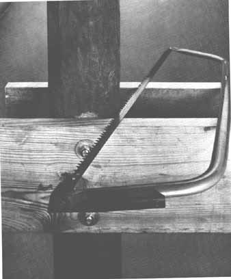
A beam-and-pole sandwich. Pairs of beams, bolted to high poles, support the floor and roof of a pole-frame cabin. To make the beams lie flat and firm against the poles, shallow notches called daps are cut with a buck saw on the sides of each pole; the beams are se cured in the daps with threaded rods and nuts.
A-Frame Cottage Built with Prefabricated Panels
The vacation house most like a year-round home has standard stud walls. Its great advantage for the amateur cabin builder is that it can be prefabricated in sections, hauled to the vacation site in a small truck and , with three or four helpers, quickly assembled on a prepared deck and topped with a simple rafter or truss roof. Using this method, you can erect the walls and roof of a cabin in a weekend.
The pre-fabricated parts are wall frames 7’ 9” high and 4’, 8’, or 7’ 8½” wide; these frames are made up of 2-by-4 studs and plates, and sheathed with ¾” plywood. Sections go together side by side to make walls of any size that's a multiple of 4’, a module suiting common building materials. Corner sections have projecting edges of sheathing that overlap to add strength. Jigs make possible, fast and easy assembly of accurately sized sections.
You need plans that indicate the exact size of your foundation walls—so the panels will fit together properly—and also show the locations of doors, windows and intersecting walls. You may be able to simplify the job by ordering the doors and windows sized to fit exactly in the space occupied by studs. When transporting the panels, place them on a truck so that the last panel loaded is the first panel to be erected. Then you can simply back the truck up to the foundation and erect the panels on the deck.
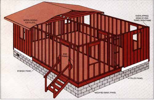
Anatomy of a prefab. This example demonstrates how
12 prefabricated panels in three sizes make up the outer walls of a 20-by-24-foot
cottage—any dimensions are attainable by varying the number of panels.
One size panel serves as the basic module; another is a filler; the third
serves for ends. At each corner, the basic panel is modified to provide
a nailing surface for a projecting edge of sheathing on the ad joining
end panel. Panels are nailed together where they abut, and firmly interconnected
by an additional, overlapping top plate. For clarity, sheathing is not
shown on some panels, but all actually are sheathed in advance.
Interior partitions are made up of the same kind of panels used for the exterior walls. The bearing partition rests on a girder running the length of the cottage. The studs at the sides of the windows illustrated are exactly 32” apart—the space of three studs. Any roof and foundation can be used.
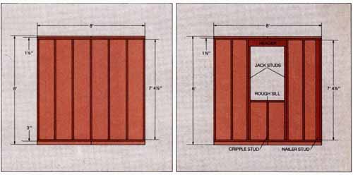
The basic panel. Middle-of-the-wall sections are prefabricated of seven 2-by-4 studs, each 7’ 4½” long, butt-nailed on 16” centers between 2-by-4 top and bottom plates, each 8’ long. The sheathing, 3 exterior-grade plywood, is nailed flush at the sides; it overlaps 1½” at the top to cover a second top plate, and 3” at the bottom so that rain drips off. The second top plate is added after the panels are erected. A basic panel 4’ wide but otherwise identical serves as a filler so walls can be made in multiples of 4’. Windows and doors can be installed in the panels as indicated in the drawings at right below.
The modified basic panel. To tie the walls together at the corners, the basic panel is modified by adding an extra stud butted to the corner stud. The extra nailer stud serves as a surface for attaching the corner panel as well as interior wallboard.
The drawing also illustrates the additional changes required in any panel to assemble a rough frame for a window: a header, made by nailing together two 2-by-6s with a ½” ply wood spacer; jack studs to support the header; a rough sill toenailed to the jack studs; and a cripple stud under the rough sill.
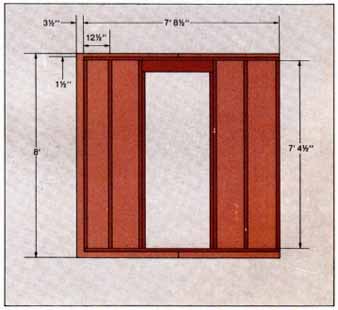
The corner panel. The frame of this panel is only 7’ 8½” long and is covered by sheathing that overlaps the corner end by 3”. The overlapped portion of the sheathing nailed to the end stud of the modified basic panel. Because the sheathing always overlaps to the right when viewed from out side, the walls must be erected from left to right. This drawing illustrates the modifications that must be made in any panel for a door: a header and jack studs like those shown above for a window in a modified basic panel.
Walls from an Assembly Line
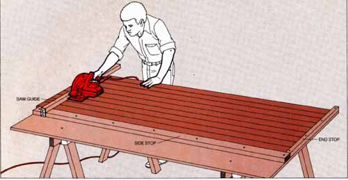
1 Mass-producing studs. Using a power saw and a jig, cut all studs for each panel at once — you need seven studs for each full-sized section without openings, plus an extra for each modified basic panel. Make the jig from a securely mounted plywood sheet. Nail an 8-foot 2-by-4 stop along one side and a 2-by-2 stop at right angles to it. At the opposite end of the side stop, hinge a 2-by-2 saw guide so that it can be lifted to slide the stud lumber underneath it.
Position the guide at right angles to the side stop so that, when the saw shoe is touching it, the saw blade will be 7’ 4½” from the end stop. Check angles and distances at several points to be sure the guide is parallel to the end stop and a proper distance from it.
2 Framing panels. For the basic panel withoutdoors or windows, butt-nail studs on 16” centers between 8-foot or 4-foot top and bottom plates. Make as many basic panels as the size of your cottage requires. Make four modified basic panels the same way except at the corners, where they adjoin end panels; there a stud assembly is built up from two 2-by-4s, the edge of one butted against the face of the other to provide a projecting nailing surface.
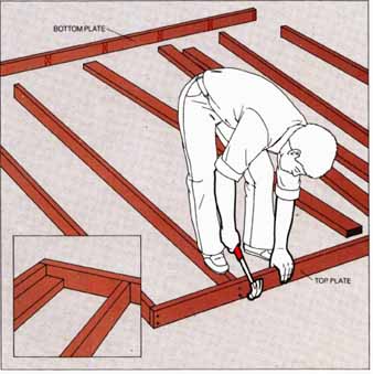
For the end panels, butt-nail studs between plates 7’ 8½” long, using 16” spacing for all studs except the one that will be at the corner; it's spaced 12½” from its neighbor. Number each panel to match your plan.
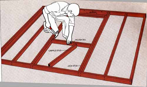
3 Framing rough openings. For a window that re quires a rough opening 30 1/2” wide, omit one stud, set the centers of the adjoining studs 35” apart and toenail across the top of the opening a header—two 2-by-6s, 33½” long with a ½” plywood spacer between; beneath the header, nail jack studs to the studs that flank the header, making each jack stud 6’ 11” long. To the jack studs toenail a 2-by-4 rough sill, carefully leveled, at the height specified by the manufacturer of your window. Butt-nail a 2-by-4 cripple stud cut to fit between the rough sill and the bottom plate. For a door with the same rough opening, install a header and studs as for a window.
4 A jig for sheathing. To a 4-by-8 sheet of ply wood, nail a 2-by-2 stop 8’ long along one end and a 2-by-4 stop 3’ 10½” long along one side. Nail a 1-by-6 to the inside of the 2-by-4 and another to the outside of the 2-by-2.

5 Sheathing basic panels. Slide each basic and modified basic panel into the jig, placing its end against the short stop and its top plate against the long stop, slide a sheet of 3 exterior- grade plywood against the 1-by-6 stops and nail to the frame beneath with galvanized six- penny nails every 6” at the edges and every 12” at intermediate studs. Slide a second sheet of sheathing plywood into place, with its side against the first sheet and its top against the long stop, and nail it as you did the first sheet.
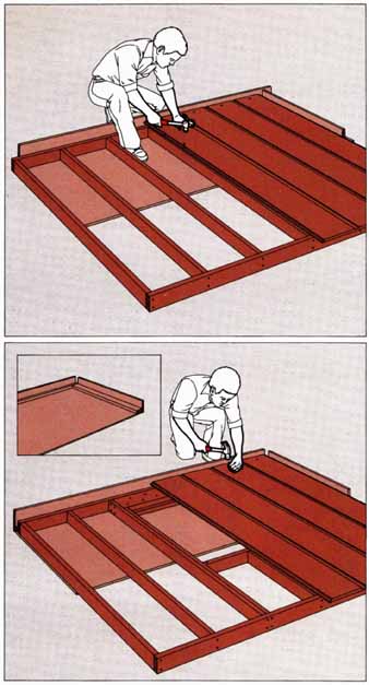
To cut the door and window openings, drill pilot holes through the interior side of the sheathing at the top and bottom of each rough frame, use a straightedge to connect the holes on the exterior side and saw out the outlined opening.
6 Sheathing end panels. Modify the sheathing jig by moving the 1-by-6 attached to the 2-by-4 stop from the inside to the outside, then slide end frames and sheathing into the jig and nail them, using the method of Step 5.

7 Flashing the openings. With metal shears, cut pieces of 6” aluminum flashing the width of each rough opening. Use a cold chisel or pry bar to loosen the sheathing around the header; then, wearing gloves, slip the flashing between the header and the sheathing, and hammer the sheathing down tight again.
Erecting the Walls
1 Bracing the first panel. After building a foundation and installing joists, tilt a modified basic panel into position at a corner, fasten the bottom plate to the subfloor and brace it with a diagonal 2-by-4 eight-foot long tacked in place. After a helper plumbs the panel, nail the brace in place and add a second brace at the other end of the panel.

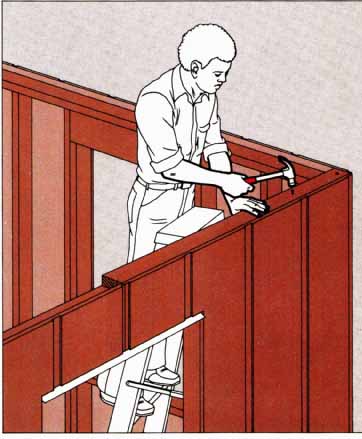
2 Extending the wall. While a helper holds the next panel in position, use a 4-pound sledge to drive the panel into alignment with the adjoining panel. If the deck is warped, drive the bottom plate of the new panel down until the end studs of both panels are flush. Secure, brace and plumb the new panel.
Erect three walls using modified basic panels at the right of each corner (as seen from outside the cottage) and end panels to complete the corners. Bring in the interior partitions and put up the fourth wall. Drive sixpenny nails through the overlapping sheathing on end panels and into the corner studs of the modified basic panels.

3 Tying the walls together. Nail a 2-by-4 plate 4’ long to the top plate of an end panel so that it overlaps the top plate of a modified basic pan el. Install additional 8-foot plates, lapping the joints between the remaining panels; cut the last plate in a wall flush with the wall end, and finish with a 4-foot plate if necessary. If a panel is bowed, have a helper push it in or out until the top plates align, before you nail them together.
Slip strips of aluminum flashing under the sheathing, overlapping the foundation wall by 3”, and drive sixpenny galvanized nails through the flashing and into header joists every 6”. Cover the edges of the sheathing at corners with butted 1-by-3s and 1-by-4s.
4 Marking for the interior wall. Snap two parallel chalk lines 3½” apart on the subfloor between the side walls. Use the girder pockets as reference points to center the lines directly over the girder.
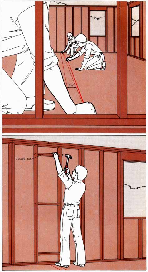
5 Setting the interior partitions. Nail 2-by-4 blocks between side-wall studs above the chalk lines made in Step 4. Fasten the blocks near the top, center and bottom of the studs. (If you plan to install wallboard inside the side walls, do it at this point.) Erect and brace the interior partitions directly over the chalk lines (Steps 1 and 2), nailing the end panels to the blocks. Tie the partitions together (Step 3).