Once some of the basic concepts are understood, wiring is not difficult. It does, however, require attention to safety and stringent adherence to electrical codes. In some parts of the country only licensed electricians can work on household wiring, while in other locales a homeowner may work on every part of his or her own house. Be sure to check local codes before beginning a wiring project.
Building codes require that the basement be supplied by at least one circuit, though at least one additional circuit will make the basement far more convenient to use. A home office has considerable electrical requirements, so plan at least one circuit for this room alone.
Tools for Wiring
If framing is exposed for “rough” wiring work (running wires and installing boxes), the only tools needed are a hammer, wire cutter, and an electric drill with a 5/8-inch auger or spade bit (for drilling through the studs). The “finished” wiring work requires a small collection of hand tools (detailed in the following list). Electrical tape is needed as well.
Fish Tape. This tool essentially is a roll of stiff wire that has a hook on one end to which wire cable is attached. It is used to pull wire through the wall. Fish tape is not needed unless the basement was finished partially at an earlier date and is now getting expanded.
Needle-nose Pliers. This is the perfect tool for snipping a wire to length and then bending the end into a tight loop to go around terminal screws.
Wire Strippers. The cutter holes on this tool match diameters of various wire gauges and easily strip insulation off the wire without nicking the wire itself.
Screwdrivers. A standard flat-blade screwdriver and a Phillips screw driver are needed.
Voltage Tester. With probes inserted, this inexpensive tool is used to test for the presence of electricity.
Service Entrance Panel. Electricity enters the house through a meter that measures the amount of electricity used. Then it flows into the service entrance panel. The panel essentially is a distribution center. It divides incoming electricity into branch circuits that serve various portions of the house. Each circuit is protected by a fuse (in older panels) or a circuit breaker (in newer panels) that cuts power to a circuit in the event of an overload or circuit fault. Each circuit is independent of the others, so when power is cut to one, the remaining circuits are unaffected and continue to supply power.
The lob of adding circuits to supply the basement consists of cutting power to the service panel, adding one or more circuit breakers, running wires throughout the basement, and connecting all of the outlets and switches to the new circuit. Those who are not familiar with this work are advised to turn it over to a licensed electrician. One cost-saving option, however, is to do the time-consuming work of routing the wiring while leaving all connections to the electrician. Be fore doing so, however, find an electrician who is willing to work this way.
--
Electrical Safety
• Always turn off the power at the main electrical service panel before beginning work.
• Always test a wire for the presence of electricity before working on it, even if you think power to the circuit has already been turned off. A voltage tester is a simple and effective testing tool.
• Always use tools that have insulated handles. Do not use screwdrivers with metal shanks that extend completely through the handle. Even if the handle itself is insulated, the exposed tip of the shank (at the end of the handle) can transmit an electrical shock.
• Never use a metal ladder when working with electricity. Use a wood or fiberglass ladder instead.

Fish Tape. This resilient metal wire is used to pull electrical cable through otherwise inaccessible places.
Needle-nose Pliers. This convenient tool is used to snip wire and bend it into a tight loop.
Wire Strippers. This tool has cutter holes with diameters to match various wire gauges. It easily strips off insulation with out nicking the wire itself.
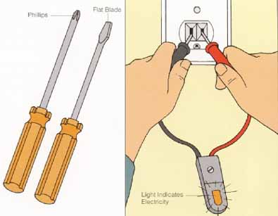
Screwdrivers. You need a standard flat-blade screwdriver and a Phillips screwdriver, each with a non-conducting handle.
Voltage Tester. The test probes of a voltage tester are touched to wires or inserted into an outlet to detect the presence of an electrical current.
Running Wires
55-1.jpg: Service Entrance Panel. Each incoming cable is connected to a separate circuit breaker. The panel shown here has room for four additional breakers, which means it can serve as many as four new basement circuits.
House circuits are usually wired with nonmetallic sheathed cable (often referred to by the trade name Romex). Nonmetallic cable is flexible and easier to work with than other types of cable. A cable contains two or more copper wires within a protective plastic sheathing and is sold by the foot or in rolls of 25, 50, or 100 feet. Aluminum wire was used widely from World War II until the mid-1970s but is no longer considered suitable for household wiring. Consult an electrician before modifying an aluminum wire system in any way.
Wiring that loops through the house is supported by cable staples. A hammer is used to drive these heavy-duty staples into the framing lumber. One box of staples is enough for most basement projects. Make sure that the staples are a suitable size in relation to the wire being used. (This information usually is found on the staple box.)
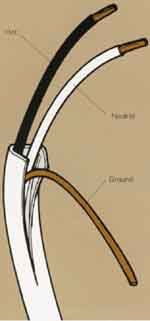
Running Wires. Nonmetallic sheathed cable is the standard
cable used in residential wiring. Its outer sheathing, made of flexible
plastic, protects several individual wires inside.
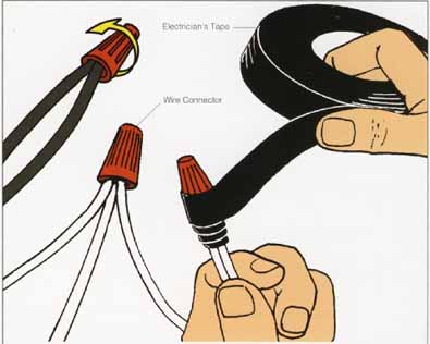
Joining Wires. Wire connectors are small plastic caps
that are screwed over the ends of wires to join them. Wrapping connections
with electrical tape is a good idea, although not required by the National
Electrical Code.
Joining Wires
At one time all wires in a household system were spliced together with solder and electrical tape. Now splices are made by joining wires with plastic caps called wire connectors. The inner portion of each cap is threaded. To join two or more wires, strip about 1/4 inch of insulation from each wire; hold the wires together; and in a clockwise motion, twist on the wire connector. (There is no need to twist the wires together first, though many people do.) Simply unscrew the connector to remove it. Connectors come in many sizes; choosing the right one depends on the number of wires to be joined and the gauge of the wires. Usually, however, a connector is used to join two or three No. 14 or No. 12 wires. For most basement wiring projects, it's cost-effective to buy a box of wire connectors in the size needed most.
Types of Cable
The individual wires (called conductors) in a cable come in a range of sizes. Circuits that serve lighting and standard receptacles, however, typically are No. 14 wire diameter (rated to carry a maximum of 15 amps) or No. 12 wire diameter (rated to carry a maximum of 20 amps). Amperage is a measure of current flow. Markings on the plastic sheathing of cable explain what is inside and identify the type of insulation that covers it. For example, consider the following designation:
14/2 WITH GROUND, TYPE NM, 600V (UL)
The number before the slash mark indicates the size of the wire inside the cable (No. 14). The number after indicates how many conductors (two in this case) are in the cable. There also is an equipment grounding wire, as indicated. (The grounding wire is not considered a conductor.) In this case, the type designation indicates a cable that's for use only in dry locations (indoors). Each wire is wrapped in its own plastic insulating sheath, though the grounding wire may be bare. Following the type is a number that indicates the maximum voltage allowed through the cable. Finally, the UL (Underwriters Laboratories) notation specifies that the cable has been certified as safe for the uses for which it was designed. For safety reasons, never use wiring or other electrical supplies that don't bear the UL notation.
Estimating Wire Needs
New wiring that leads from the ser vice panel to the first switch or outlet in the basement must be of a continuous, unbroken length. The code allows certain exceptions to this, but a single length is ideal and nearly always possible. Wiring may have to be snaked over, around, or through a number of obstructions as it's routed through the basement. Rather than try to calculate the length of this path, simply begin with a 25-foot roll of wiring. In most cases this is more than enough and the excess can be used for general wiring in the basement.
When running wire through a structure in which all the walls and new partitions are exposed, it's fairly easy to figure out the amount of wire needed. Measure the distance between each connection to be made; add a foot for every connection; and then add 20 percent to the total to provide a margin of error.
Wiring Framed Walls
Running wire from the service panel through the basement is usually easier than running it to other parts of the house. Every house calls for a different strategy, but the following guide provides some techniques for solving typical problems. Wires are not connected to a power source until they have been safely connected to outlets or fixtures.
1. Wiring at the Panel. Start the run with a 4-foot tail of wire at the service panel. This allows enough wire for the electrician to connect the circuit breaker.
2. Securing Cable. Use cable staples to support the cable at 4-foot intervals (or according to local code). Do not damage the outer casing of the wire as you drive the staple home. Support the cable on both sides of a corner.
3. Drilling Through Framing. In places where cable passes through framing, drill a ¾” diameter hole to allow room to pull the wiring. Though a spade bit can be used, an auger bit is easier and safer. Auger bits are available at many hardware and home supply stores. When drilling through framing, the hole must be at least 1¼ inch away from the edge of the stud or joist to minimize the risk that a paneling or drywall nail will hit the wire. If the hole is closer than 1¼ inches, the National Electrical Code requires that the wiring be protected with a metal plate. (Plates are available at many hardware stores and other places where electrical supplies are sold.)
4. Drilling Through Joists. Use the same bit used for drilling through studs to drill through joists. Always put the hole in the center one-third of the board. (The joist is weakened when drilled through the bottom third, and nails may get in the way if it's placed in the upper third.)
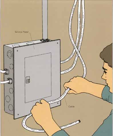
1--When stringing cable to new circuits, leave its 4-ft. tail
near the box so that the electrician can connect it to the proper circuit
breaker.
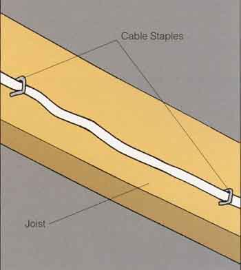
2--Metal cable staples are used to hold cable to the sides of
joists. The staples are hammered in place but should not pinch the cable.
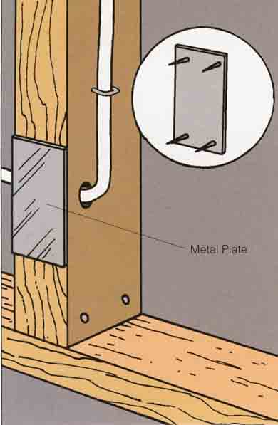
3-- Cable that passes close to the edge of a joist or stud must
be protected by a nailing plate. Use a hammer to pound the plate against
the wood; barbs on the back of the plate hold it in place.
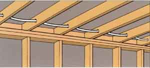
4 -- Use auger bit and an electric drill to bore through joists.