Electric ranges come in a variety of sizes and shapes, but they all work in pretty much the same way. They operate on a 120/240-volt circuit. Typically, 120 volts are used for the light and clock, 240 volts for the heating elements. However, some older models might have heating elements made of two coils controlled by a switch that applies either 120 or 240 volts to either or both of the coils, depending on the heat setting. Newer ranges usually have single-coil elements operated by a thermostatically controlled switch. These switches smoothly regulate the temperature from low to high, and at any point in between. Self-cleaning ovens use a cycle that raises the temperature of the oven to about 900 degrees F. This high temperature burns off any cooking residues from the oven walls. An automatic safety door lock prevents the oven door from being opened until the cleaning cycle ends and the oven temperature lowers to about 300 degrees.
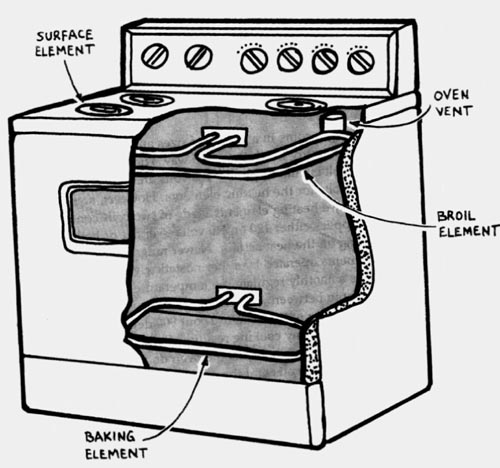
Before making any repairs, always turn off the power at the service entrance panel. Let heating elements cool completely before touching them. Always open and close the range's lift-up cook top carefully to avoid straining any wires.
When making some of the tests, you need to refer to the wiring diagram provided by the manufacturer. You should find it stuck on the inside of the control or back panel, depending on the type of range you have.
-----------
Tools & Materials:
Steel wool
Volt-ohmmeter or continuity tester
Emery board
Screwdriver
==========
TROUBLESHOOTING GUIDE
---------
Problem:
No elements heat; lights are out
One cooktop element doesn't heat
Oven doesn't heat
Oven doesn't maintain set temperature
Oven light out
-----------
Probable cause:
No power to range
Faulty element
Element receptacle faulty
Burner switch faulty
Faulty oven element
Automatic timer improperly set
Faulty oven temperature control
Faulty oven selector switch
Oven temperature control improperly calibrated
Bulb burned out
Faulty light switch
----------
Solutions:
Check for tripped circuit breaker.
Check element.
Check element receptacle.
Check burner switch.
Check element.
Reset timer to manual.
Check oven temperature control.
Check oven selector switch.
Check and recalibrate oven temperature control.
Replace bulb. Check light switch.
==============
-----------
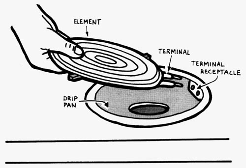
Step 7- Checking a top element.
First turn off the power to the range. Then lift the edge of the element just enough to clear the drip pan. Pull the element straight out. Use steel wool to polish any corroded terminals on the element. Remove another element of the same size that works properly, and plug the suspect element into the receptacle of the working element. Restore power to the range and turn on the burner. If the suspect element does not heat now, replace it with a new one. If the element does heat, check the element's terminal receptacle, If the range does not have another element that is the same size, check the suspect element with a volt-ohmmeter (Step 7-2).
-----------
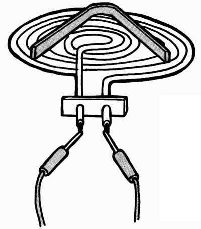
Step 7-2. Checking a burner element with a volt-ohmmeter. With the element unplugged and the volt-ohmmeter set on the R x 1 scale, touch a probe to each of the two terminals of the element. The needle should move, showing continuity.
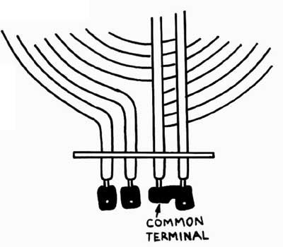
Step 7-3. Testing the element's terminals. If the heating element has two separate coils, it should have three terminals-one common terminal connecting the two coils together and two individual terminals on the other ends of the coils. Touch one probe to the common terminal and the other probe to each of the other two terminals. In each case the needle should swing, indicating continuity. If not, replace the heating element with a new one.
-----------
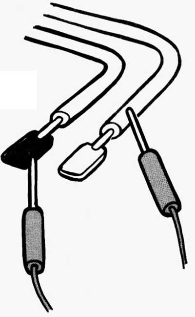
Step 7-4. Testing the element for a short.
If the element checks as good, touch one probe to one of the terminals and the other probe to the outer metal cover of the element. The needle should not move, indicating no continuity. If the needle does move, the element is shorted. Replace it with a new one.
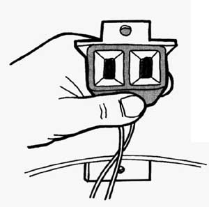
Step 7-5. Checking the element receptacle. With the power off and the element removed, lift out the drip pan. Disconnect the receptacle from the top of the stove and carefully pull it out for inspection. Check the slots that the element plugs into. If the slots are dirty polish them carefully with a thin fingernail emery board. If the slots are charred or broken, install a new receptacle.
-----------
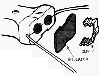
Step 7-6. Replacing the receptacle. In some receptacles, the wires are connected by screws covered by an insulator. Remove the insulator and loosen the screws to disconnect the wires. In other receptacles, the wires are connected by wire connectors. Use needle-nose pliers to unplug these connectors from the terminals on the receptacle. Connect the wires to the new receptacles and reinstall any insulators. Remount the receptacle and install the drip pan.
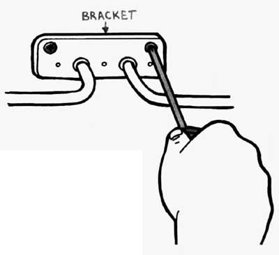
Step 7-7. Checking the oven element. First turn off the power to the range. Now remove the screws holding in any front or rear brackets that support the element. Remove the screws fastening the element to the back wall of the oven.
-----------
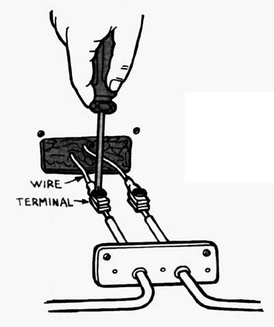
Step 7-8. Removing the oven element. Carefully pull the element out a few inches to expose the wire connections. Disconnect the two wires from the terminals. Remove the element.
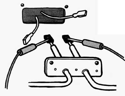
Step 7-9. Testing the oven element. Set the volt-ohmmeter on the R x 1 scale and touch a probe to each of the two terminals.
The needle should move, showing continuity.
If not, install a new element.
----------
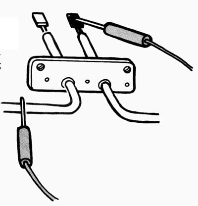
Step 7-10. Testing the oven element for a short. If the element shows continuity touch one probe to one of the terminals and the other probe to the metal cover of the element. The needle should not move, indicating no connection. If it does move, replace the element with a new one. Install the new element in the reverse order, making sure all brackets are securely mounted.
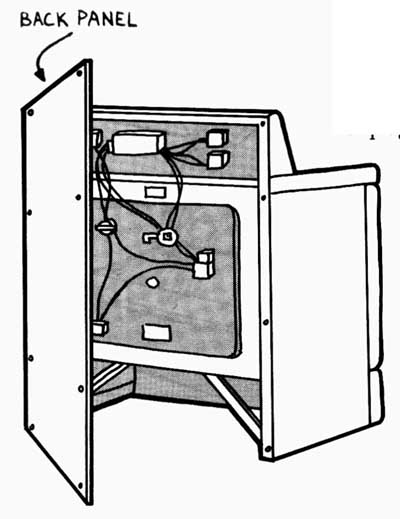
Step 7-11. Preparing to check the burner switches. Disconnect the power to the range. If it is a free-standing range, pull it away from the wall, unplug it, and remove the back panel.
-----------
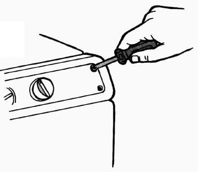
Step 7-12. Removing the control panel. If the controls are mounted on the front of the range, remove the screws holding the control panel in place.
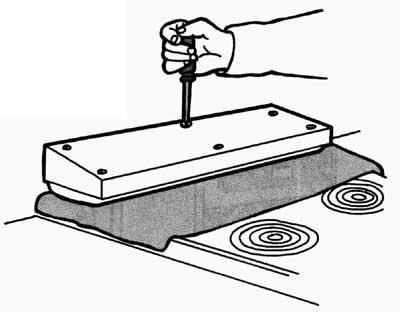
Step 7-13. Removing the control panel's rear panel. If you have a built-in range with the controls mounted on the backsplash, spread an old towel on top of the stove for protection. Then remove the screws from each end cap, tilt the backsplash forward, and remove the rear panel. You should now have access to the burner switches, the oven temperature control, and the oven selector switch. You should also notice the wiring diagram.
-------------
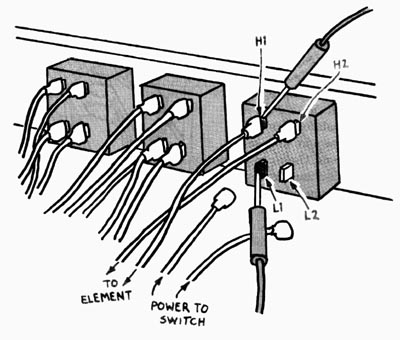
Step 7-14. Testing the burner switches.
Inspect each burner switch for visible damage, such as burned wire connections or loose connectors. Replace any damaged switch. The wires supplying power to the switch are connected to terminals marked L1 and L2. Wires running to the burner element might be numbered 1 and 2 or marked H1 and H2 (see the wiring diagram). Disconnect the wires marked L1 and L2 from the suspect switch. Set the volt-ohmmeter to the Rx 1 scale. Touch one probe to the terminal marked L1 and the other probe to each of the terminals connected to the wires leading to the burner element. You do not have to disconnect the element wires. As long as you have the other side of the switch (L1 and L2) disconnected, you can test the switch. With the switch on, the needle should move, indicating continuity. With the switch off, the needle should not move, indicating no connection. Repeat the test with one of the probes touching the terminal marked L2 and the other probe touching each of the element wire terminals in turn. Repeat the test on a burner switch that you know works properly, and compare the results. If the readings don't match, replace the suspect switch with a new one.
------------
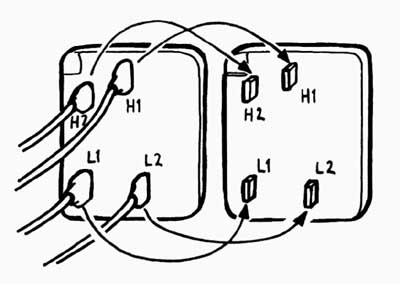
Step 7-15. Installing a new switch. When installing the new switch, label the wires and draw a simple wiring diagram before disconnecting the wires, or leave the wires connected to the old switch and transfer them one at a time to the new switch.
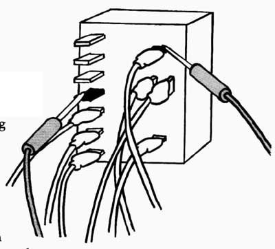
Step 7-16. Checking the oven selector switch. With the power disconnected and the control panel removed, look at the wiring diagram and locate the terminals for each setting (bake, broil, time bake, etc.) on the selector switch. You should see a pair of terminals for each setting. Disconnect one wire from each pair of terminals. Use a continuity tester or a volt-ohmmeter set to the R x 1 scale and touch one probe to each of the terminals in the pair. The needle on the meter should swing to 0, showing continuity. Check each setting on the switch. If any setting fails the test, install a new switch. To install a new switch, label each wire and draw a simple wiring diagram. Disconnect the wires and remove the old switch from its mounting. Mount the new switch and reconnect the wires to the proper terminals.
------------
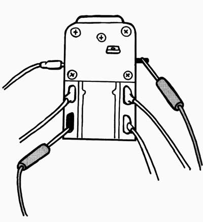
Step 7-17. Testing the oven temperature control. With the power turned off and control panel removed, use a continuity tester or a volt-ohmmeter set on the R x 1 scale to check the oven temperature control for continuity. If more than two wires are connected to the control, refer to the wiring diagram on the inside of the control panel or on the back panel to determine which pair of terminals to test. Now disconnect one wire from the pair of terminals you are testing, turn the control switch to about 300 degrees F and touch a probe to each of the two terminals, if the needle fails to move, indicating no continuity install a new temperature control.
-------------
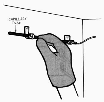
Step 7-18. Installing a new oven temperature control. To replace the oven temperature control, first carefully un-clip the capillary tube from its supports in the oven and gently push it through the rear wall. Caution: If this oven is a self-cleaning model, wear rubber gloves and goggles-the tube is probably filled with highly corrosive chemicals. If you happen to get any of these chemicals on your skin, put the entire area under a steady flow of running water immediately. Then seek medical help. With the wires all labeled and disconnected, disconnect and remove the temperature control and the capillary tube. Install a new temperature control and connect the wires to the proper terminals. Next install the new capillary tube, being careful not to bend or break it.
-------------
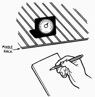
Step 7-19. Checking the calibration of the oven temperature control. Place an oven thermometer on a rack in the middle of the oven. Turn the oven on and adjust the temperature to 350 degrees F. Heat the oven about 20 minutes. Then check the thermometer. Write down the temperature. Check the thermometer 3 more times at 10-minute intervals, recording the temperature at each check. The average of these readings should be within 25 degrees of the 350-degree setting to be normal. If your average is off by 50 degrees, recalibrate the temperature control. If the average is off by more than 50 degrees, replace the temperature control with a new one.
-------------
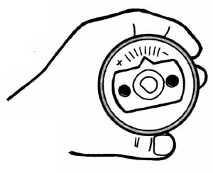
Step 7-20. Calibrating the oven temperature control. To calibrate the oven temperature control on some ovens, pull off the control knob and look on its back side. Loosen any screws or clips and turn the movable disk in the direction marked on the knob to raise or lower the temperature. You first might have to loosen a retaining screw that holds the disk in its set position. Typically, one notch represents a 10-degree change in temperature. If moving the disk more than two notches is required to adjust the thermostat, install a new temperature control (Step 7-18).
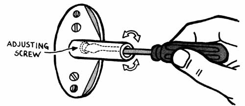
Step 7-21. Calibrating the oven temperature control. To calibrate the oven temperature control on other ovens, pull off the control knob and locate the adjusting screw inside the hollow shaft that fits into the knob. Turning the screw clockwise lowers the temperature setting; turning the screw counterclockwise raises it. Turn the screw very slightly. If it requires more than about an eighth of a turn, install a new temperature control (Step 7-18).
-----------
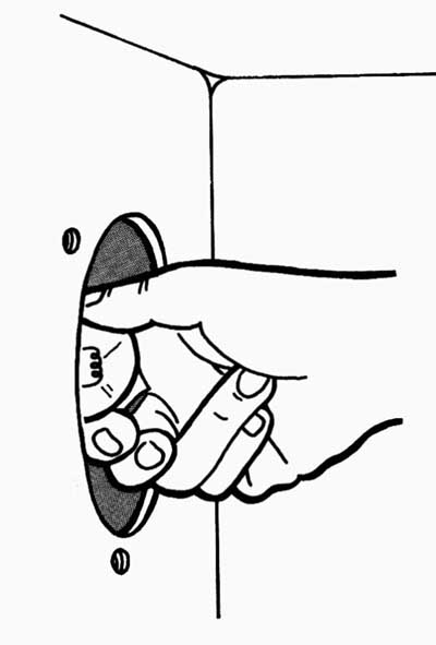
Step 7-22. Replacing the oven bulb. Turn off the power to the range and remove the glass shield covering the bulb. Using gloves or a dry cloth, unscrew the bulb. Screw a 40-watt bulb into the socket. Restore the power. If the bulb lights, the old bulb was faulty. Remove the 40-watt bulb and install an appliance bulb of the proper size and wattage. Reinstall the shield. If the light bulb wasn't the problem, check the light switch.
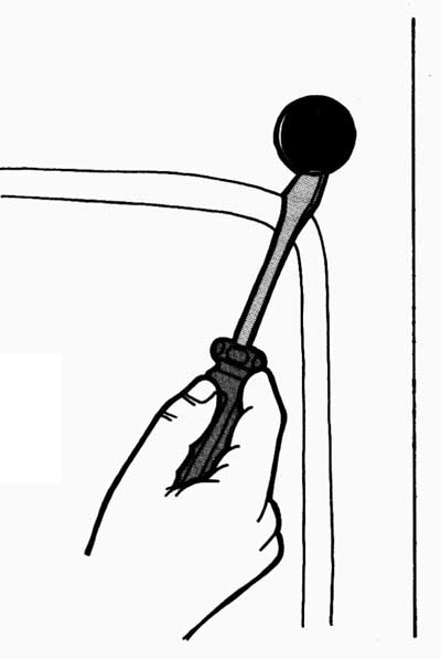
Step 7-23. Removing the light switch.
Turn off the power and open the oven door.
Use a screwdriver to carefully pry the switch from the front of the oven.
-------------
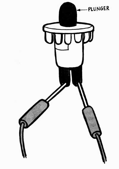
Step 7-24. Testing the light switch. Disconnect the wires from the switch's terminals. Use a continuity tester or volt-ohmmeter set on the R x 1 scale to test the switch for continuity. Touch a probe to each of the two terminals on the switch. The needle should move, showing continuity. Now push in the switch plunger. The needle should swing in the other direction, showing no continuity, If your results differ, install a new switch. Connect the wires to the new switch and press the switch back into the opening.
Home Guide/index top of page