Troubleshooting and Repairing--Automatic dryers
| HOME | Troubleshooting | DIY Tips |
| HOME | Troubleshooting | DIY Tips |
|
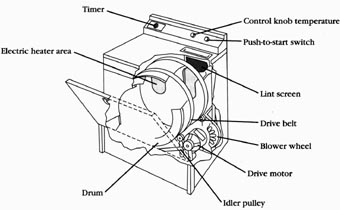
Automatic electric dryers are not complicated to repair. The more that you know about the electrical, mechanical, and operational basics of the dryer, the easier it’s to solve the problem. Some models are designed to operate on 240 volts, but other models operate on 120 volts. To dry clothing, an automatic dryer must have drum rotation, electric heat, and air circulation. This section will provide the basic skills needed to diagnose and to repair automatic dryers. Figr. --1 identifies where the components are located within the automatic dryer. --Electric heater area
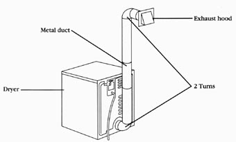
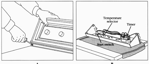
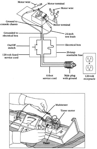
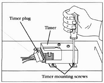
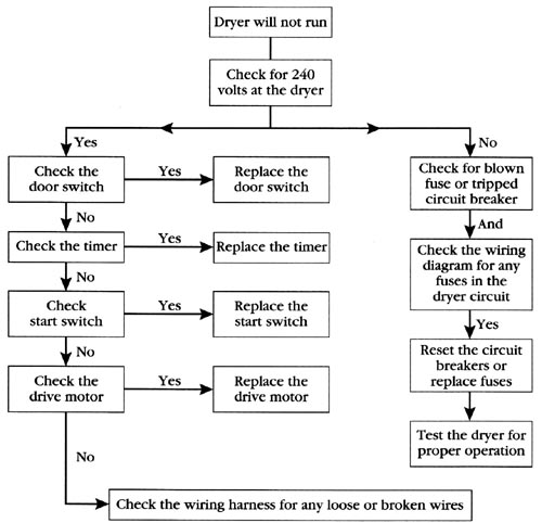
PRINCIPLES OF OPERATION The clothes are placed into the dryer according to the manufacturers recommendation for the proper loading of the dryer. Next, the proper cycle is selected, and the dryer start button is pressed. The combination of the timer, the switches, and the thermostats regulates the air temperature within the drum arid the duration of the drying cycle. During the drying cycle, room air is pulled into the dryer drum from the lower rear (or sometimes the front) of the cabinet, depending on which model the consumer owns. The air is pulled through the heater, drum, lint screen and down through the lint chute, through the fan housing, and it’s then pushed out of the exhaust duct. The drive motor, blower wheel, belt, and pulleys cause the drum to turn, and the air to move through the dryer. The belt wraps around the drum, mo tor pulley, and idler pulley. The blower wheel is secured to one end of the drive mo tor shaft. As the drive motor turns, the drum rotates, moving the clothes. At the same time, the blower wheel turns, moving the air; and the heating element will cycle on and off, according to the temperature selected. --Functions and cycles Electric automatic dryers use three basic functions to operate: 1. Heat is supplied by a resistance-type heating element. 2. Air is drawn into the dryer. It’s heated and circulated through the tumbling clothes. Then, the warm, moisture laden air is drawn through the lint screen, and it’s vented through the duct system to the outside. 3. Tumbling of the clothes is accomplished with a motor that drives a belt, that rotates the drum. • Timed dry cycle--The timed dry cycle is controlled by the amount of time selected on the timer. The temperature in the dryer is controlled by a thermostat, which turns the heating element on and off throughout the timed cycle. • Automatic dry cycle --The automatic dry cycle is not controlled by the timer. This cycle is controlled by the cycling thermostats. Heat is supplied to dry the clothes, and it will continue until the temperature in the drum reaches the selected cutout setting of the thermostat. When the thermostat is satisfied, the heater shuts off, and the timer motor is activated. But, there are variables available that can control the cycle, which will cause the cycling of the thermostat before the end of the cycle. • Permanent press and knit cycle --The permanent press and knit cycle are controlled by the amount of time selected on the timer. The temperatures of these cycles are controlled by the temperature rating of the cycling thermostats that are located within the cabinet, on the exhaust duct, and in the air supply. On some models, the user can select the desired type of heat setting with the temperature selector switch, located on the control panel. • Air dry --The air dry cycle is controlled by the amount of time selected on the timer. This cycle, uses the air to dry the clothes. The heating element is not used at all during this cycle. SAFETY FIRST Any person who cannot use basic tools, or follow written instructions, should not attempt to install, maintain, or repair any automatic dryers. Any improper installation, preventive maintenance, or repairs could create a risk of personal injury or property damage. If you don’t fully understand the installation, preventive maintenance, or repair procedures in this section; or if you doubt your ability to complete the task on the automatic dryer; then please call your service manager. The following precautions should also be followed: 1. Never bypass (or interfere with) the operation of any switch, component, or feature. 2. The dryer exhaust should be vented properly. Never exhaust the dryer into a chimney, a common duct, an attic, or a crawl space. 3. Be careful of sharp edges when working on the dryer. 4. The dryer produces combustible lint, and the area should be kept clean. 5. Never remove any ground wires from dryer; nor the third (grounding) prong from the service cord. 6. Never use an extension cord to operate a dryer. 7. The wiring used in dryers is made with a special heat-resistant insulation. Never substitute it with ordinary wire. Before continuing, take a moment to refresh your memory of the safety procedures in Section 2. AUTOMATIC DRYERS IN GENERAL Much of the troubleshooting information in this section covers automatic electric dryers in general, rather than specific models, in order to present a broad overview of service techniques. The pictures and illustrations that are used in this section are for demonstration purposes to clarify the description of how to service dryers. They in no way reflect upon a particular brands reliability. --Electrical requirements Electrical dryers can be connected to an electrical power source in three ways: 1. Electrical cord and plug, which plugs into a 240-volt wall receptacle. 2. Directly wired to a fused electrical disconnect box with a built-in shut-off switch. 3. Directly wired to a circuit breaker or to a fuse panel. All dryers must be properly wired, grounded, and polarized, according to the manufacturer’s installation instructions, and per all local codes and ordinances. --Location and installation of dryer Listed are some general principles that should be followed when installing a dryer. 1. Locate the dryer where there is easy access to existing electrical lines. 2. Be sure that you observe all local codes and ordinances for the electrical, plumbing and venting connections. 3. The dryer should be installed and leveled on a firm floor, to minimize vibration during operation. 4. To reduce the risk of fire, never install a dryer on any type of carpeting. 5. For proper operation of the dryer, be sure that there is adequate make-up (new, replacement) air in the room where it’s installed. 6. Don’t install a dryer in an area where the make up air is below 45 degrees Fahrenheit. This will greatly reduce the drying efficiency, and increase the cost of operating the dryer. 7. Always follow the installation instructions which are provided with every automatic dryer model purchased. If the installation instructions are not available, order a copy from the manufacturer. 8. When installing a dryer in a mobile home, the dryer must have an outside exhaust. If the dryer exhaust goes through the floor, and the area under the mobile home is enclosed, the exhaust must terminate outside of the enclosed area. 9. If the dryer is to be installed in a recessed area, or closet area, follow the manufacturer’s recommendation for its installation. 10. When relocating the dryer to a new location, test the voltage at the new location, and be sure that it matches the dryer voltage specifications, as listed on the nameplate (serial plate). Also, inspect the entire vent system for any obstructions. --Proper exhausting of the dryer Proper exhausting instructions for the model being installed are available through the manufacturer. Each manufacturer has their own specifications for the size and the length of the ductwork needed to run their dryer properly. The maximum length of the exhaust system depends upon the type of duct, the number of elbows, and the type of exhaust hood used. Figr. --2 illustrates a typical dryer exhaust installation. The following guide is recommended for the exhausting of a dryer: 1. Keep the duct length as short as possible. 2. Keep the number of elbows to a minimum, to minimize the air resistance. 3. Never reduce the diameter of round ductwork below four inches. 4. Install all exhaust hoods at least 12 inches above ground level. 5. The exhaust duct, and exhaust hood, should be inspected periodically, and cleaned, if necessary. Dryer: 6. All duct joints should be taped. Never use screws to join the duct joints together. Screws protruding into the duct will cause lint build-up, and this will eventually clog the duct. 7. Never exhaust the dryer into any wall, ceiling, attic, or under a building. Accumulated lint could become a fire hazard, and moisture could cause damage. 8. If the exhaust duct, is adjacent to an air conditioning duct, the exhaust duct must be insulated to prevent moisture build-up in the duct. STEP-BY-STEP TROUBLESHOOTING BY SYMPTOM DIAGNOSIS In the course of servicing an appliance, don’t overlook the simple things that might be causing the problem. Step-by-step troubleshooting, by symptom diagnosis, is based on diagnosing malfunctions, with possible causes arranged into categories relating to the operation of the dryer. This section is intended only to serve as a check list; to aid you in diagnosing a problem. Look at the symptom that best describes the problem that you are experiencing with the dryer, then correct the problem. Dryer won’t run: 1. Do you have the correct voltage at the dryer? 2. Test the door switch for continuity of the switch contacts. 3. Test for the continuity of the motor windings. Also check for a grounded motor. 4. Test the timer for the continuity of the switch contacts. 5. Test the push to start switch for the continuity of the switch contacts. 6. Check for broken or loose wiring. Also check the wire terminal connections that connect to the different components. --No heat 1. Do you have the correct voltage? The motor in a dryer runs on 120 volts. The heating element works on 240 volts, and on compact models 120/240 volts. Check voltage at the wall receptacle. Also, check the nameplate voltage rating for the model that you are working on. 2. Check for any in-line fuses that might have blown. Refer to the wiring diagram, located on the rear of the dryer, or behind the console panel. 3. Are the thermostats functioning properly? 4. Test the timer for the continuity of the switch contacts. 5. Test for continuity of the motor windings. Also, test for a grounded motor. 6. Test the heating element for continuity. 7. Test the temperature selector switch for continuity. 8. Check for broken or loose wiring. --Drum won’t rotate 1. Check the drive belt. Is it broken or worn? 2. Check the idler pulley. Is the pulley seized up? 3. Check the drum support bearings. Be sure that they rotate freely. 4. Is the dryer overloaded with clothing? 5. Check for foreign objects that might be lodged between the drum and the bulkheads. --Dryer noisy 1. Check for loose components. Is everything secure, and in its proper place? 2. Check the idler pulley. Lint build-up can cause the idler pulley shaft to squeak. 3. Check the drive belt. Is the belt partially torn? 4. Check the drive motor. Is the pulley secured to the shaft? Also, check the fan assembly. Is it loose? 5. Check for lint, or foreign objects, lodged between the drum and the bulkheads. 6. Check the front and rear bearings. 7. Check the blower assembly. Be sure that the blower wheel is tight on the motor shaft end. 8. Is the dryer level? --Dryer runs and heats, but the clothes won’t dry 1. Check for a defective thermostat. Use a thermometer to check the duct temperatures during the cycling of the dryer. 2. Check for a loose pulley or blower wheel. Inspect and tighten the blower wheel. 3. Check for restricted air flow. 4. Check exhaust vent. --Clothes too hot or fabric damage 1. Check the exhaust system for restrictions. 2. Checks for air leaks in the ductwork, and the drum front and rear seals. 3. Check the thermostats. 4. Check the temperature setting by customer. 5. Check the door latch and strike. 6. Inspect the interior of drum for any foreign objects protruding into the drum. COMMON DRYING PROBLEMS The drying of clothes will depend on several factors: 1. Clogged lint screen. 2. Exhaust duct to long, collapsed, or crimped. 3. If dryer air is exhausted into the area where the dryer is located. For example: the dryer is located inside a closet, and operating with the closet door closed. 4. Overloading of clothing in the dryer. 5. If dryer is located in an area where the temperature is below 45 degrees Fahrenheit. 6. Laundry washed in cold water will take slightly longer to dry. 7. The moisture content of certain clothes. Towels and denim retain more moisture, etc. 8. Wrong spin speed selected, for the type of laundry being washed. For example: Towels, denim, blankets, small rugs, etc. 9. Electric supply is less than what is needed to operate the dryer efficiently. 10. Load type (towels, bedspreads, jeans, etc.) All of these must be taken into account, when diagnosing a complaint of clothes not drying properly. --Lint Lint consist of fibers that have broken away from the fabric. It can collect inside the dryer cabinet and base, and create a fire hazard. This lint should be removed every one to two years by cleaning it out. Some lint can also collect in the door opening, the drum, the heater assembly, the blower assembly, and the duct assembly. This accumulation of lint should be removed periodically, when performing maintenance on the dryer; otherwise, it could create problems with the future use of the dryer. The lint screen should be cleaned every time the dryer is used. The duct system, that exhausts the air to the outside of the dwelling, should also be cleaned out every one to two years. --Shrinkage Shrinkage is caused by over-drying, and by the type of fabric being dried. To reduce the shrinking of cotton and rayon knits, it’s recommended that, while the clothing is still damp, the user remove them from the dryer and lay them on a flat surface to air dry. Also, you might suggest to the user to set the heat setting on a lower setting. Before drying any synthetic clothing in a dryer, the user should read the label on the garment for the proper drying instructions, and for the proper heat selection. The user should read the use and care manual for the proper instructions when operating the dryer. --Stains Greasy looking--Stains are caused by: 1. Fabric softener that is designed for use in the dryer. 2. Fabric softener that was undiluted when the clothes were washed. 3. Not enough detergent being used in the wash. This will cause the soil in the water to stick to the outer tub, and to return to the next load being washed. 4. Drying of clothing that already has a stain on it. Brown stains on the clothing are caused by: 1. Fabric softener that is designed for use in the dryer. 2. Leaving the wash in the washer tub, after the cycle is completed. 3. Leaving the wet clothing in the dryer, for an extended amount of time. 4. Transmission seal leaking. Static electricity: Static electricity in the clothes is caused by over-drying the clothes. To reduce this condition, you must instruct the user to reduce the amount of time the clothes are to be dried, and to use a lower temperature setting. Static electricity in synthetics is normal. To reduce this condition, use a liquid fabric softener in the wash cycle or use a fabric softener that is designed for use in the dryer. --Wrinkling Wrinkling of the clothes is caused by: 1. Not using the permanent press cycle which has a cooling down period, during which the heating element is not on. 2. Clothing not removed from the dryer, after it has completed the cycle. 3. Overloading the dryer. The clothes need the room to tumble freely without getting tangled. 4. The quality of the permanent press material in the garment might be poor. AUTOMATIC DRYER MAINTENANCE Automatic dryers and exhaust ducts must be cleaned periodically. The excess lint must be removed to prevent the possibility of a fire, and the possibility of the dryer not functioning properly. Most models have a service panel on the front of dryer, for accessibility. The outside of the cabinet should be wiped with a damp cloth. It’s recommended that the components be inspected for wear and tear; if repairs are needed, they should be made as soon as possible. REPAIR PROCEDURES Each repair procedure is a complete inspection and repair process for a single dryer component. --Dryer timer The typical complaints associated with the dryer timer are: 1. The dryer won’t run at all. 2. The clothes are not drying. 3. The dryer won’t stop at the end of the cycle. 4. The timer won’t advance through the cycle. 1. Verify the complaint--Verify the complaint by operating the dryer through its cycles. Before you change the timer, check the other components controlled by the timer. 2. Check for external factors-- You must check for external factors not associated with the appliance. Is the appliance installed properly? Does the appliance have the correct voltage? 3. Disconnect the electricity--Before working on the dryer, disconnect the electricity. This can be done by pulling the plug from the electrical outlet. Or disconnect the electricity at the fuse panel or at the circuit breaker panel. Turn off the electricity. 4. Remove the console panel to gain access To gain access to the timer, remove the screws that secure the console to the top of the dryer ( Figr. --3). On other models, to gain access, remove the back panel behind the console. 5. Test the timer--There are two ways to check the timer: A. Connect a 120-volt fused service cord to the timer motor to see if the timer motor is operating ( Figr. --4). Connect the ground wire of the 120-volt fused service cord to the console ground. Be cautious when working with live wires. Avoid getting shocked. The timer motor operates on 120 volts. If the motor does not operate, replace the timer. If the timer motor runs, but does not advance the cams, then the timer has internal defects, and it should be replaced. B. Set the ohmmeter range to R x 100, disconnect the timer motor leads, and check for resistance ( Figr. --5). The meter should read between 2000 and 3000 ohms. Next, test the timer switch contacts with the wiring diagram’s configuration for the affected cycle. Place the meter probe on each terminal being tested, and turn the timer knob. If the switch contact is good, your meter will show continuity. 6. Remove the timer To remove the timer, pull the timer knob from the timer stem; then remove the timer mounting screws. Remove the wire lead terminals from the timer. Mark the wires as to their location on the timer. Some timers have a quick disconnect, instead of individual wires, which makes it easier to remove the timer wires. 7. Install a new timer--To install a new timer, just reverse the disassembly procedure, and reassemble. Replace the wires on the timer. Reinstall the console panel, and restore the electricity to the dryer. Test the dryer for proper operation. --Dryer motor The typical complaints associated with motor failure are: 1. Fuse is blown, or the circuit breaker trips. 2. Motor won’t start; only hums. 3. The dryer won’t run. 1. Verify the complaint Verify the complaint by operating the dryer through its cycles. Listen carefully, and you will hear if there are any unusual noises, or if the circuit breaker trips.
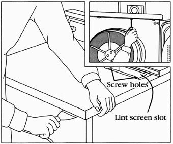
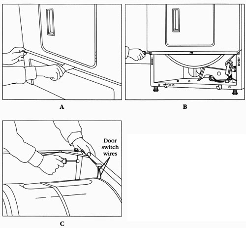
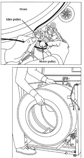
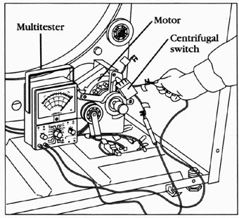
2. Check for external factors-- You must check for external factors not associated with the appliance. Is the appliance installed properly? Does the appliance have the correct voltage? 3. Disconnect the electricity--Before working on the dryer, disconnect the electricity. This can be done by pulling the plug from the electrical outlet. Or disconnect the electricity at the fuse panel or at the circuit breaker panel. Turn off the electricity. 4. Gain access to the motor In order to gain access to the motor, the top must be raised ( Figr. --7) by removing the screws from the lint screen slot. Insert a putty knife about two inches from each corner; then, disengage the retaining clips and lift the top. On some models, the top is held down with screws (see inset in Figr. --7). Remove the screws and lift the top. Now, the front panel of the dryer must be removed ( Figr. --8). To remove the toe panel, insert a putty knife and disengage the retaining clip ( Figr. --8A). On some models, the toe panel is held in place with two screws. In Figr. --8B, remove the screws that hold the lower part of the front panel in place. Next, remove the screws that hold the upper part of the front panel in place ( Figr. --8C), and then disconnect the door switch wires (label them). With the front panel out of the way, you can now disconnect the drive belt ( Figr. --9). Push on the idler pulley to release the tension from the drive belt, and remove the belt from the motor pulley. Grab the drum and remove it from the cabinet (Figr. --10). On some models, you will have to remove the back panel because the drum comes out through the rear of the cabinet. 5. Disconnect the motor wire leads Disconnect the motor wire leads from wiring harness. Set the ohmmeter on R x 1. Figr. --11 illustrates testing the motor windings and the centrifugal switch for continuity. When testing for resistance on the motor, test from the common wire lead to the run winding. Then, test for resistance from the common wire lead to the start winding. Next, test for resistance from the start winding to the run winding.
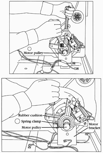
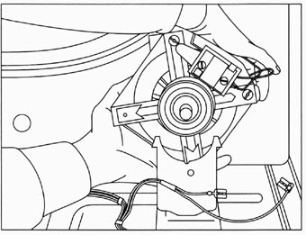
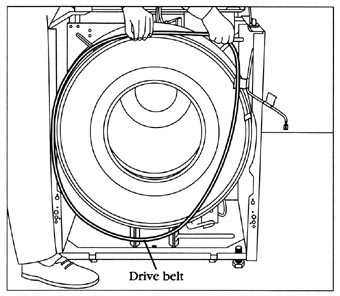
To test for a grounded winding in the motor, take the ohmmeter probes and test from each motor wire lead terminal to the motor housing. The ohmmeter will indicate continuity, if the windings are grounded. If the ohmmeter reading shows no resistance between the motor windings, then replace the motor. If the motor checks good, then check the timer. 6. Remove the motor--To remove this type of motor, you must first disconnect the blower assembly by holding the motor shaft stationary, and then turning the blower wheel to remove it from the rear of the motor shaft ( Figr. --12). Then, remove the spring clamps that hold the motor in the motor bracket ( Figr. --13). On some models, the motor pulley must be removed (new motors come without the pulley attached), by loosening the allen set screw. 7. Install the new motor To install the new motor ( Figr. --14), just reverse the disassembly procedure, and reassemble. Then, reassemble the dryer in the reverse order of its disassembly. Restore the electricity to the dryer and test the motor. --Drive belt The typical complaints associated with belt failure are: 1. The drum won’t turn. 2. Dryer motor spins freely. 3. Smells like something is burning. 1. Verify the complaint--Verify the complaint by operating the dryer through its cycles. Listen carefully, and you will hear if there are any unusual noises. Then, with the door open, press the door switch and start the dryer. The drum should rotate. 2. Check for external factor-- You must check for external factors not associated with the appliance. Is the appliance installed properly? Does the appliance have the correct voltage? Check for foreign objects lodged between the drum and bulkhead, etc. 3. Disconnect the electricity Before working on the dryer, disconnect the electricity. This can be done by pulling the plug from the electrical outlet. Or disconnect the electricity at the fuse panel or at the circuit breaker panel. Turn off the electricity. 4. Gain access to the drive belt--To gain access to the drive belt, the top must be raised ( Figr. --7) by removing the screws from the lint screen slot. Then, insert a putty knife about 2 inches from each corner, and disengage the retaining clips and lift the top. On some models, the top is held down with screws (see the inset in Figr. --7). Remove the screws and lift the top. Now, the front panel of the dryer must be removed ( Figr. --8). To remove the toe panel, insert a putty knife and disengage the retaining clip ( Figr. --8A). In Figr. --8B, remove the screws that hold the lower part of the front panel in place. Next, remove the screws that hold the upper part of the front panel in place ( Figr. --8C), and then disconnect the door switch wires. 5. Remove the drive belt To remove the drive belt on this type of dryer, you can now disconnect the belt ( Figr. --9). Push on the idler pulley to release the tension from the drive belt. Now, remove the belt from the motor pulley, and from around the drum ( Figr. --15). If the drive belt is broken, just remove the belt. 6. Install a new drive belt To install the new drive belt, just reverse the disassembly procedure, and reassemble. Then, reassemble the dryer in the reverse order of its disassembly. Restore the electricity to the dryer and test. --Heater element The typical complaints associated with heater failure are: 1. The dryer won’t dry the clothes properly. 2. There is no heat at all when a heat cycle is selected. 1. Verify the complaint--Verify the complaint by operating the dryer through its cycles. Then, open the dryer door, and place your hand inside to see if it’s warm in the drum. 2. Check for external factors-- You must check for external factors not associated with the appliance. Is the appliance installed properly? Is the exhaust vent clogged? Check the voltage to the dryer. Note: the dryer motor runs on 120 volts, but the heater works on 240 volts.
3. Disconnect the electricity Before working on the dryer, disconnect the electricity. This can be done by pulling the plug from the electrical outlet. Or disconnect the electricity at the fuse panel or at the circuit breaker panel. Turn off the electricity. 4. Gain access to the heater assembly You must gain access to the heater assembly through the back. Remove the exhaust duct from the dryer. Then, remove the screws from the back panel ( Figr. --16).
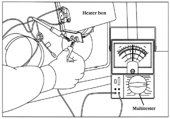
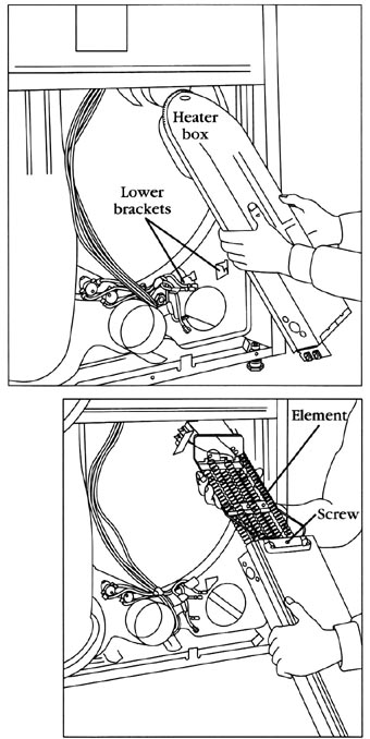
5. Test the heater element To test the heater element, set the ohmmeter on R x 1. Remove the wires from the heater ( Figr. --17), and test for continuity. If it’s ok, check the thermostats. 6. Remove the heater element To remove the heater in this type of dryer, you must first remove the screw and the bracket that holds the heater box in place. It’s located on top of the heater box. You can gain access through the back of the dryer, or lift the top and reach in near the back bulkhead. Then, slide the heater box up, and pull it away at the bottom ( Figr. --18). With the heater box Out of the dryer, remove the screw that holds the heater element in place ( Figr. --19). Pull the heater element out of the heater box. 7. Install new heater element To install the new heater element, just reverse the disassembly procedure, and reassemble. Then, reinstall the back panel. Restore the electricity to the dryer and test it. --Door switch The typical complaints associated with switch failure are: 1. Dryer won’t operate at all. 2. Dryer light not working when the door is open. 1. Verify the complaint --Verify the complaint by operating the dryer through its cycles. Open the door to see if the light is working. 2. Check for external factors -- You must check for external factors not associated with the appliance. Is the appliance installed properly? Does the dryer have the correct voltage supply? 3. Disconnect the electricity --Before working on the dryer, disconnect the electricity. This can be done by pulling the plug from the electrical outlet.
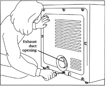
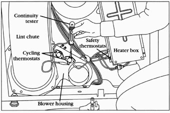
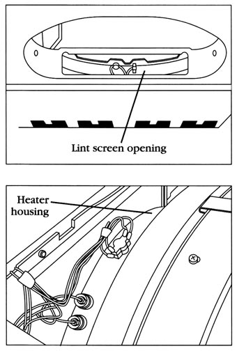
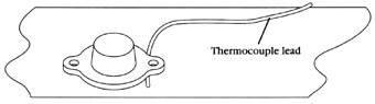
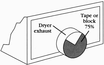
Or disconnect the electricity at the fuse panel or at the circuit breaker panel. Turn off the electricity. 4. Gain access to the door switch -- You must gain access to the door switch. On this model, the top must be raised ( Figr. --7), by removing the screws from the lint screen slot. Then, insert a putty knife about 2 inches from each corner, disengage the retaining clips, and lift the top. On some models the top is held down with screws (see the inset in Figr. --7). Remove the screws and lift the top. 5. Test the door switch --The door switch is located in one of the upper corners of the inside of the front panel ( Figr. --20A). Once you have located the door switch, disconnect the wires from the terminals. Set the ohmmeter on R x 1, attach the probes of the ohmmeter to the terminals of the door switch, and then close the door. With the door closed, there should be continuity. With the door open, the ohmmeter should not show continuity. Some dryer models have a light inside the drum. This light circuit is also part of the door switch circuitry. There will be three terminals located on the door switch. Take your ohmmeter probe and place it on the common terminal of the door switch. To locate the common terminal, read the wiring diagram. It will indicate which terminal is the common, which is the light and is for the motor circuit. Take your probe and place it on the switch terminal (the light circuit), then close the dryer door. The reading should indicate no continuity. Now, open the dryer door, you should have a continuity reading on the meter. 6. Remove the door switch --To remove the lever-type door switch ( Fig. ___20B), remove the screws that hold the switch in place. Now, lift the switch Out from behind the front panel. To remove the cylindrical type of door switch ( Figr. --20C), squeeze the retaining clips on the back side of the front panel, and pull out the switch. To remove the hinge type of door switch ( Figr. --20D), the front panel must be removed. Next, remove the screws that hold the switch assembly in place. 7. Install the new door switch To install the new door switch, reverse the disassembly procedure, and reassemble. Reassemble the dryer, and install the wires on the new switch terminals. Plug in the dryer and test it. Lever switch. ___20 A. Testing the door switch for B; continuity B. Removing the screws that secure the door switch. C. Removing a cylindrical door switch. D. Removing a hinge-mounted door switch. C, D --Thermostat The typical complaints associated with thermostat failure are: 1. The clothes are not drying. 2. The dryer won’t shut off. 3. The dryer won’t heat at all. 4. The drying temperature is too high. 5. Moisture retention (of fabrics) is unsatisfactory. 1. Verify the complaint--Verify the complaint by operating the dryer through its cycles. 2. Check for external factors-- You must check for external factors not associated with the appliance. Is the appliance installed properly? Does the dryer have the correct voltage supply? Is the exhaust vent blocked? 3. Disconnect the electric--Before working on the dryer, disconnect the electricity. This can be done by pulling the plug from the electrical outlet. Or disconnect the electricity at the fuse panel or at the circuit breaker panel. Turn off the electricity. 4. Gain access to the thermostat-- You must gain access to the thermostat through the back on this model. Remove the screws from the back panel ( Figr. --16). 5. Test the thermostat To test the thermostat for continuity, remove the wires from the thermostat terminals. With a continuity tester, or an ohmmeter, test the thermostat for continuity ( Figr. --21). Do this to all of the thermostats in the dryer. On some models, the thermostats might be located on the heater housing, behind the drum, or in the lint screen opening ( Figr. --22). If they all check good, then reassemble the dryer and test for temperature operation. Take note, don’t reinstall the back panel. Take a piece of paper and write down the temperature ratings of the thermostats. These ratings are printed on the thermostats (L140, L290, etc.). To test for temperature operation, you will need a voltmeter and a temperature tester. First, set up the test instruments for testing the thermostatic operation. Take the temperature tester thermocouple lead and insert it in between the thermostat mounting ear ( Figr. --23) and the plate against which it mounts. Then, connect the voltmeter probes across the thermostat terminals. Use alligator clips attached to the probe tips. This will allow you freedom of movement. Don’t disconnect the wires from the thermostat. Set the voltmeter range to ac voltage, and the selector switch on 300 volts. Another thing to remember, if there is more than one thermostat (in parallel with other thermostats), the thermostats not under test must be electrically isolated. Review the wiring schematic to determine which wires to remove and which ones to isolate. With the test meters in place, you are now ready to remove the exhaust vent duct from the dryer. Seal off 75% of the exhaust opening from the dryer ( Figr. --24). This will simulate a load of clothing in the dryer. Lint screen opening:
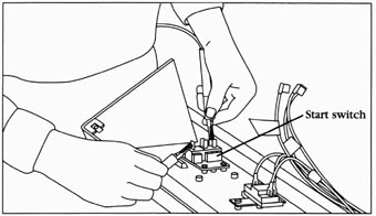
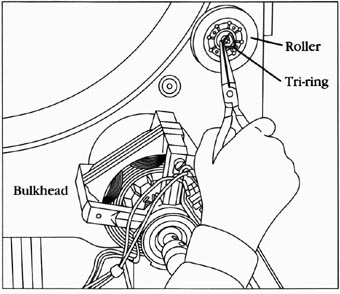
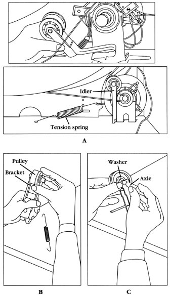
Restore the electricity to the dryer. This test requires that the electricity be turned on for its duration. Always be cautious when working with live wires. Avoid getting shocked. Set the controls on the dryer to operate at a high heat. Turn on the dryer and let it cycle. When the voltmeter is reading voltage, the thermostat has opened. When there is no voltage reading on the voltmeter, the thermostat is closed. As the dryer is cycling, via the thermostat, record the temperature. The thermostat should open at the preset temperature listed on the thermostat. Table ___1 illustrates the types of thermostat with their opening and closing temperature settings. The temperature range of the thermostat should be within ±10% of the printed setting. If not, replace the thermostat. Caution: turn off the electricity before replacing any parts of the dryer. 6. Replace the thermostat --Remove the screws that hold the thermostat in place. Replace the thermostat with an exact replacement of the same temperature rating. Reconnect the wires to their correct terminal positions. Then, reverse the disassembly procedure to reassemble the dryer; and test the thermostat. 7. Test the new thermostats --To test the new thermostats, repeat step 5. --Start switch The typical complaint associated with the start switch is that the dryer won’t start. 1. Verify the complaint: Verify the complaint by operating the dryer. Before you change the start switch, check the other components that are in the start circuit. 2. Check for external factors: You must check for external factors not associated with the appliance. Is the appliance installed properly? Does the appliance have the correct voltage? 3. Disconnect the electricity --Before working on the dryer, disconnect the electricity. This can be done by pulling the plug from the electrical outlet. Or disconnect the electricity at the fuse panel or at the circuit breaker panel. Turn off the electricity. 4. Remove the console panel to gain access Begin with removing the console panel, to gain access to the start switch. With this type of dryer, remove the screws from the console ( Figr. --3A). On some models, the console will be able to lay flat ( Figr. --3B). 5. Test the start switch Remove the wires from the start switch terminals. Set the ohmmeter on R x 1. Begin testing the start switch for continuity by placing one probe of the ohmmeter on the common terminal (C) of the switch, then connect the other probe to the normally open (NO) terminal. There should be no continuity. With the ohmmeter probes attached to the switch, press the start switch button. You should have continuity ( Figr. --25). If the switch fails the test, replace it. 6. Remove the start switch --To remove the start switch, pull the knob off the switch stem, remove the start switch mounting screws, and remove the switch. 7. Install a new start switch --To install a new start switch, just reverse the disassembly procedure, and reassemble. Replace the wires on the switch. Reinstall the console panel, and restore the electricity to the dryer. Test the dryer operation. --Drum roller The typical complaints associated with the drum roller are: 1. Dryer very noisy when operating. 2. Dryer has a burning smell. 1. Verify the complaint --Verify the complaint by operating the dryer through its cycles. 2. Check for external factors: You must check for external factors not associated with the appliance. Is the appliance installed properly? Does the dryer have the correct voltage supply? 3. Disconnect the electricity --Before working on the dryer, disconnect the electricity. This can be done by pulling the plug from the electrical outlet. Or disconnect the electricity at the fuse panel or at the circuit breaker panel. Turn off the electricity. 4. Gain access to the drum roller --To gain access to the drum roller, the top must be raised ( Figr. --7) by removing the screws from the lint screen slot. Then, insert a putty knife about two inches from each corner to disengage the retaining clips, and lift the top. On some models, the top is held down with screws (see the inset in Figr. --7). Remove the screws and lift the top. Now, the front panel of the dryer must be removed ( Figr. --8). To remove the toe panel, insert a putty knife and disengage the retaining clip ( Figr. --8A). As in Figr. --8B, remove the screws that hold the lower part of the front panel in place, then remove the screws that hold the upper part of the front panel in place ( Figr. --8C). Disconnect the door switch wires. 5. Remove the drive belt and drum --To remove the drive belt and the drum on this type of dryer, you must first disconnect the belt ( Figr. --9). Push on the idler pulley to release the tension from the drive belt. Remove the belt from the motor pulley and from around the drum ( Figr. --15). Grab hold of the drum and remove it from the cabinet ( Figr. --10). 6. Remove the drum roller-- Once the drum has been removed, the drum rollers, which are located on the rear bulkhead of this model ( Figr. --26), can then be removed. Take a pair of needle-nose pliers and remove the tri- ring off the shaft. Then, slide the roller off the shaft. 7. Install a new drum roller To install the new roller, clean the shaft and lubricate it with a small amount of oil. Slide the new drum roller onto the shaft, and reinstall the tri-ring. To reassemble the dryer, just reverse the disassembly procedure, and reassemble. Test the dryer for proper operation. --Idler pulley The typical complaints associated with the idler pulley are: 1. When dryer is running, you will hear a squealing noise. 2. The dryer belt burns, and might snap. 3. The dryer drum won’t turn. 1. Verify the complaint Verify the complaint by operating the dryer through its cycles. 2. Check for external factors You must check for external factors not associated with the appliance. Is the appliance installed properly? Does the dryer have the correct voltage supply? 3. Disconnect the electricity Before working on the dryer, disconnect the electricity. This can be done by pulling the plug from the electrical outlet. Or disconnect the electricity at the fuse panel, or at the circuit breaker panel. Turn off the electricity. 4. Gain access to the idler pulley To gain access to the idler pulley, in this type of dryer, remove the toe panel, insert a putty knife, and disengage the retaining clip ( Figr. --8A). 5. Remove the idler pulley To remove the idler pulley, you must first remove the drive belt. To disconnect the belt on this model ( Figr. --9), push on the idler pulley to release the tension from the drive belt. Now, remove the belt from the motor pulley, and from around the idler pulley. If the drive belt is broken, just remove the belt. Next, lift the idler pulley up and out of the dryer ( Figr. --27). This type of idler pulley is replaced as a complete assembly. Another type of idler pulley ( Figr. --28A) has a tension spring. To remove this type of idler, you must first remove the tension spring ( Figr. --28B), and then lift the idler assembly out of the dryer. Inspect the pulley for wear. If it’s worn, remove the screw from the axle, and pull the axle out. On this type of idler pulley, only replace the worn out part.
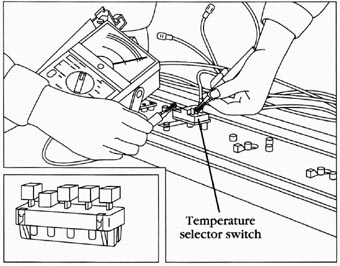
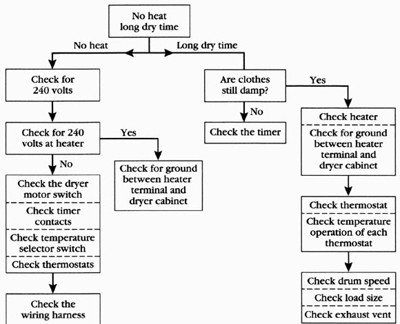
6. Install the new idler pulley To install the repaired idler pulley, just reverse the disassembly procedure, and reassemble it. Reassemble the dryer in the reverse order of its disassembly and test it for proper operation. --Temperature selector switch The typical complaints associated with the temperature selector switch are: 1. In ability to select a certain temperature setting. 2. No heat. 1. Verify the complaint Verify the complaint by operating the dryer through its cycles. Before you change the temperature selector switch, check the other components controlled by this switch. 2. Check for external factors You must check for external factors not associated with the appliance. Is the appliance installed properly? Does the appliance have the correct voltage? 3. Disconnect the electricity Before working on the dryer, disconnect the electricity to the dryer. This can be done by pulling the plug from the electrical outlet. Or disconnect the electricity at the fuse panel or at the circuit breaker panel. Turn off the electricity. 4. Gain access to the temperature selector switch To access the temperature selector switch, remove the console panel. On this type of dryer, remove the screws in the console ( Figr. --3A). On some models, the console will be able to lay flat. On other models, your access is through the rear panel on the console. 5. Test the temperature selector switch To test the temperature selector switch, locate the selector switch circuit on the wiring diagram. Identify the terminals that are regulating the temperature setting to be tested. Set the ohmmeter on the R x 1 scale. Next, place the ohmmeter probes on those terminals. Then, select that temperature setting by either rotating the dial or by depressing the proper button on the switch ( Figr. --29). If the switch contacts are good, your meter will show continuity. Test all of the remaining temperature settings on the temperature selector switch. Remember to check the wiring diagram for the correct switch contact terminals (those that correspond to the setting that you are testing).
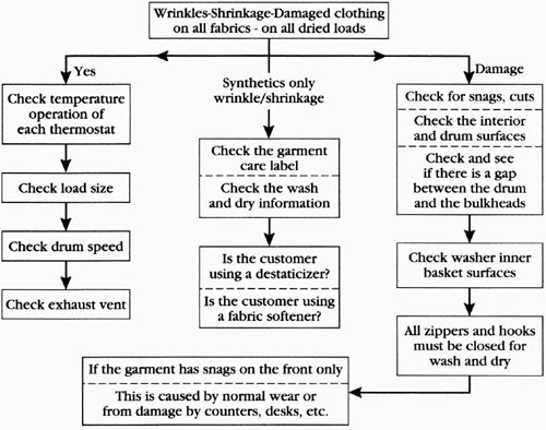
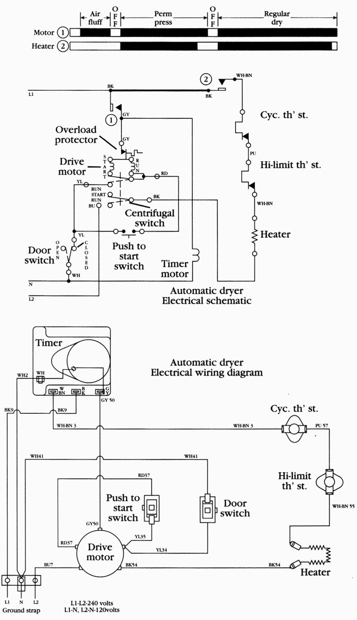
6. Remove the temperature selector switch To remove the temperature selector switch, remove the screws that hold the switch to the console base, and remove the switch. 7. Install the new temperature selector switch To install the new temperature selector switch, just reverse the disassembly procedure and reassemble it. Then, reattach the wires to the switch terminals according to the wiring diagram. Reassemble the console panel. Be sure that, when you are reassembling the console panel, the wires don’t become pinched between the console panel and the top of the dryer. DIAGNOSTIC CHARTS The following diagnostic flow charts will help you to pinpoint the likely causes of the dryer problems (Figs. ___30, ___31, and ___32). No heat long dry time No heat--Long dry time Are clothes: Yes No: Check heater Check for 240--Yes--Check the timer--Check for ground volts at heater--I--between heater --terminal and -- No--Check for ground--dryer cabinet Check the dryer--between heater -- motor switch terminal and dryer cabinet--Check thermostat—Check timer--contacts--Check temperature -- operation of each selector switch thermostat -- Check thermostats Check drum speed Check load size Check the wiring harness--Check exhaust vent The wiring diagram in this section is only an example. You must refer to the wiring diagrams on the dryer that you are servicing. Figr. --33 depicts an actual wiring schematic diagram and an actual pictorial electrical wiring diagram. Figr. --34 depicts an actual ladder diagram. A ladder diagram is simpler and it’s usually easier to read. --Test the dryer for proper operation Check the wiring harness for any loose or broken wires Wrinkles-Shrinkage-Damaged clothing on all fabrics - on all dried loads Synthetics only -- Check temperature -- wrinkle/shrinkage -- Check for snags, cuts operation of -- Check the interior each thermostat and drum surfaces Check the garment--Check and see care label if there is a gap; Check load size Check the wash between the drum and dry information and the bulkheads; Check drum speed; Is the customer; Check washer inner using a de-staticizer; basket surfaces; Check exhaust vent Is the customer using a fabric softener? All zippers and hooks must be closed for: If the garment has snags on the front only from damage by counters, desks, etc. Prev: Automatic Washer--part 2 Next: Electric ranges and ovens Home top of page All related articles |