Troubleshooting and Repairing--Automatic Washer (part 2)
| HOME | Troubleshooting | DIY Tips |
|
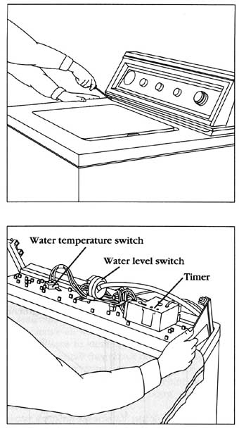
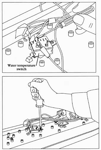
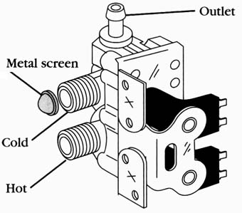
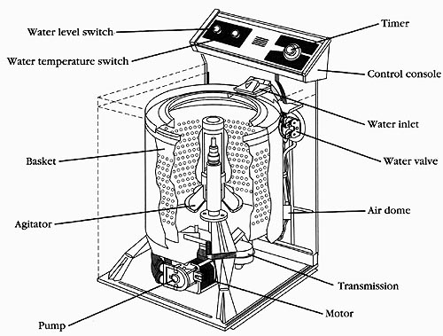
REPAIR PROCEDURES Each repair procedure is a complete inspection and repair process for a single washer component; containing the information you need to test a component that might be faulty; and to replace it, if necessary. --Washer timer The typical complaints associated with washing machine timer failure are: 1. The cycle won’t advance. 2. The washer won’t run at all. 3. The washer won’t fill. 4. The washer won’t pump the water out. 5. The washer won’t shut off. 1. Verify the complaint Verify the complaint by operating the washer through its cycles. Before you change the timer, check the other components controlled by the timer. 2. Check for external factors You must check for external factors not associated with the appliance. Is the appliance installed properly? Does the appliance have the correct voltage? 3. Disconnect the electricity Before working on the washer, disconnect the electricity. This can be done by pulling the plug Out from the electrical outlet. Be sure that you only remove the washer plug. Or disconnect the electricity at the fuse panel or the circuit breaker panel. Turn off the electricity. 4. Remove the console panel to gain access Begin with removing the screws from the console panel to gain access to the timer ( Figr. --2). Roll the console toward you. 5. Test the timer Remove the timer motor leads from the timer assembly. Test the timer motor by connecting the ohmmeter probes to the timer motor leads ( Figr. --3). Set the range on the ohmmeter to R x 100. The meter should indicate between 2000 and 3000 ohms. Next, test the timer switch contacts, with the wiring diagrams configuration for the affected cycle. Place the meter probe on each terminal being tested, and turn the timer knob. If the switch contact is good, your meter will read continuity. If the timer motor measures suitably, then connect a 120-volt, fused service cord ( Figr. --4) to the timer motor leads. Note: Connect the ground (common) wire test lead to the console ground wire. Be cautious whenever you are working with “live” wires. Avoid any shock hazards. If the motor does not operate, replace the timer. If the timer motor runs, but does not advance the cams, then the timer has internal defects and should be replaced. 6. Remove the timer To remove the timer, remove the timer mounting screws ( Figr. --5). Remove the wire lead terminals from the timer. Mark the wires as to their location on the timer. Some timers have a disconnect block, instead of individual wires, which makes it easier to remove the timer wires. Turn the timer knob counterclockwise, to remove it from the timer shaft, and slide the indicator dial off the shaft. 7. Install a new timer To install a new timer, just reverse the disassembly procedure, and reassemble. Replace the wires on the timer. Reinstall the console panel, and restore the electricity to the washer. Test the washing machine cycles. --Water temperature selector switch The typical complaints associated with the water temperature selector switch are: 1. Inability to select a different water temperature. 2. The consumer inadvertently selected the wrong water temperature. 1. Verify the complaint Verify the complaint by trying to select different water temperatures. 2. Check for external factors You must check for external factors not associated with the appliance. Is the appliance installed properly? Is there any physical damage to the component? Are the fill hoses connected to the hot and cold water supply correctly? Be sure that both the hot and cold water faucets are turned on. 3. Disconnect the electricity Before working on the washer, disconnect the electricity. This can be done by pulling the plug out from the electrical outlet. Be sure that you only remove the washer plug. Or disconnect the Fused 1 20-volt service cord -- Checking the washer timer motor Ground lead - Also grounded to electrical box (green) -- 120-volt fused service test cord. • Electrical box Li - Hot lead (black) 20-A resettable fuse Neutral lead (white) plug; On/Off switch 24-inch cord with three rubber insulated, NEC color-coded alligator clips Remove timer screws; Removing the timer; electricity at the fuse panel or at the circuit breaker panel. Turn off the electricity. 4. Remove the console panel to gain access Begin with removing the console panel to gain access to the water temperature selector switch ( Figr. __2). 5. Test the water temperature selector switch--To test the water temperature selector switch, remove all wires from the switch. Lab & the wires. Remember, you will have to identify the wires according to the wiring diagram, in order to reinstall them back onto the water temperature selector switch properly. Take your ohmmeter and check for continuity on the switch contacts. Press or turn the switch that coincides with the terminals that are being checked ( Figr. --6). At this point, you have to use the wiring diagram to identify the switch contacts. 6. Remove the water temperature selector switch--To remove the water temperature selector switch, remove the screws that hold the component to the console panel ( Figr. --7). 7. Reinstall the water temperature selector switch To reinstall the water temperature selector switch, just reverse the disassembly procedure, and reassemble. Note: you will have to identify the wires according to the wiring diagram in order to reinstall them back onto the water temperature selector switch properly. Reinstall the console panel, and restore the electricity to the washer. Test the washing machine water temperature cycles. Water valve: The typical complaints associated with water valve failure ( Figr. --8) are: 1. The washer won’t fill with water. 2. The washer will overfill, and leak onto the floor. 3. When the washer is off, water still enters the tub. 1. Verify the complaint Verify the complaint by operating the washer through its cycles. Listen carefully, and you will hear whether the water is entering the washer.
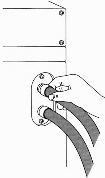
__7 Removing the water temperature switch. Metal 2. Check for external factors-- You must check for external factors not associated with the appliance. Is the appliance installed properly? Does the appliance have the correct voltage? Is the water turned on? 3. Disconnect the electricity--Before working on the washer, disconnect the electricity. This can be done by pulling the plug from the electrical outlet. Be sure that you only remove the washer plug. Or disconnect the electricity at the fuse panel or at the circuit breaker panel. Turn off the electricity. 4. Gain access to the water valve--Turn off the water supply to the water valve. To access the water valve, the rear panel must be removed. Disconnect the fill hoses from the inlet end of the water valve ( Figr. __9). Next, remove the screws that hold the water valve to the chassis of the washer ( Figr. --10). 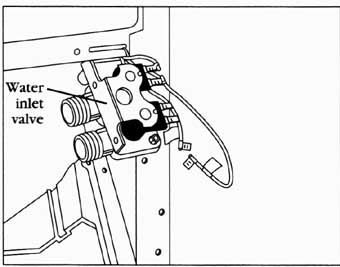
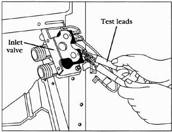
5. Test the water valve--In order to check the solenoid coils on the water valve, remove the wire leads (and label them) that connect to the coils from the wire harness ( Figr. --10). These are slide-on terminal connectors attached to the ends of the wire. Just pull them off. Set the ohmmeter on R x 100, and attach the probes to the terminals of one of the solenoid coils ( Figr. --11). The meter should read between 500 and 2000 ohms. Repeat this test for the second solenoid coil. To test the fill rate of the water valve, just reverse the disassembly procedure, and reassemble the water valve. The rear panel does not have to be reinstalled for this test. Attach the 120-volt fused service cord; including the ground wire test lead to the cabinet ground ( Figr. --4); to the water valve solenoid coil ( Figr. –1-1). Then, energize the solenoid coil to allow water to enter the tub, and to check the flow rate of the water valve. This step is repeated for each solenoid coil. If, when you energize the water valve, no water enters the washer tub, replace the water valve. If the water valve checks correctly, then check the timer and the wiring harness. Table 10: Water fill rate for a typical water valve; Water input P.S.I. Gallon per minute | one side of valve | Gallon per minute| both sides of valve 6. Remove the water valve--To remove the water valve, follow the instructions in step 4. Remove the water outlet hose from the water valve. 7. Install a new water valve--To install the new water valve, just reverse the disassembly procedure, and reassemble. Reconnect the s leads to the solenoid coils. After the installation of the new valve, turn on the water supply and check for water leaks. If none are found, reinstall the rear panel and restore the electricity to the washer. Set the timer and the water temperature control settings to operate the washer through its cycles.
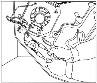
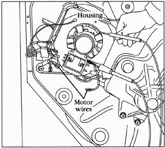
--Washer motor The typical complaints associated with motor failure are: 1. Fuse is blown, or the circuit breaker trips. 2. Washer fills up with water, and the motor won’t run. 1. Verify the complaint--Verify the complaint by operating the washer through its cycles. Listen carefully, and you will hear if there are any unusual noises, or if the circuit breaker trips. 2. Check for external factors-- You must check for external factors not associated with the appliance. Is the appliance installed properly? Does the appliance have the correct voltage? 3. Disconnect the electricity-Before working on the washer, disconnect the electricity. This can be done by pulling the plug from the electrical outlet. Be sure that you only remove the washer plug. Or disconnect the electricity at the fuse panel or at the circuit breaker panel. Turn off the electricity. 4. Gain access to the motor--To access the motor, the back panel must be removed ( Figr. --12). The back panel is held on with screws. Remove the screws and remove the panel. 5. Disconnect the motor wire leads--Disconnect the motor wire leads from the wiring harness. Set the ohmmeter on R x 1, and attach the probes to the motor lead wires ( Figr. --13). Refer to the wiring diagram for the common, start, and run motor winding leads identification. Test these for continuity, from the common wire lead to the run winding. Then, test for continuity from the common wire lead to the start winding. Next, test for continuity from the start winding to the run winding. To test for a grounded winding in the motor, take the ohmmeter probes and test from each motor wire lead, to the motor housing ( Figr. --14). The ohmmeter will indicate continuity if the windings are grounded. If the motor has no continuity between the motor windings, then replace the motor. If the motor checks OK, then check the timer, and motor relay (if the model that you are repairing has one).
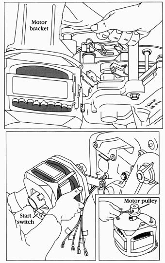
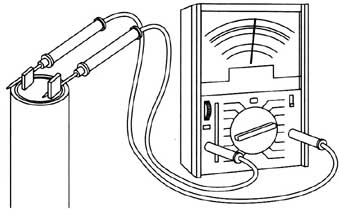
6. Remove the motor--To remove this type of motor, you must first loosen the two nuts that hold the motor support bracket ( Figr. --15). Then, slide the assembly to disengage the belt from the pulley. Next, remove the four nuts that hold the motor to the motor support bracket ( Figr. __16). Remove the motor from the washer. Remember to remove any remaining wires from the motor, and label them. Remove the pulley from the motor after loosening the set screw. 7. Install the new motor--To install the new motor, just reverse the disassembly procedure, and reassemble. To adjust the belt, refer to the “drive belt” section of this section (step 5). Restore the electricity to the washer, and test the motor. If the motor is working, reinstall the back panel. Capacitor: The typical complaints associated with capacitor failure are: 1. Fuse is blown, or the circuit breaker trips. 2. Washer motor won’t run. 3. Motor has burning smell. 4. Motor will try to start, and then shuts off. 1. Verify the complaint--Verify the complaint by operating the washer. Listen carefully, and you will hear if there are any unusual noises, or if the circuit breaker trips. If you smell something burning, immediately turn off the washer, and pull the plug. 2. Check for external factors-- You must check for external factors not associated with the appliance. Is the appliance installed properly? Does the appliance have the correct voltage? __16 Removing the motor and then the pulley. 3. Disconnect the electricity--Before working on the washer, disconnect the electricity. This can be done by pulling the plug from the electrical outlet. Be sure that you only remove the washer plug. Or disconnect the electricity at the fuse panel or at the circuit breaker panel. Turn off the electricity. 4. Gain access to the capacitor--Some models have the capacitor mounted on the motor, and some are mounted to the cabinet interior, in the rear of the machine. Access might be achieved through the front or rear panels, depending on which model you are working. Don’t touch the capacitor until it’s discharged. Warning: A capacitor will hold a charge indefinitely; even when it’s not currently in use. A charged capacitor is extremely dangerous. Discharge all capacitors immediately, any time that work is being conducted in their vicinity. Re-discharge after repowering the equipment, if further work must be done. 5. Test capacitors Before testing the capacitor, it must be discharged. Use a screwdriver, with an insulated handle, to discharge the capacitor by shorting it across both terminals. Remove the wire leads, one at a time, with needle nose pliers. Set the ohmmeter on the highest scale, place one probe on one terminal and the other probe on the other terminal ( Figr. --17). Observe the meter action. While the capacitor is charging, the ohmmeter will read nearly zero ohms for a short period of time. Then, the ohmmeter reading, will slowly begin to return toward infinity. If the ohmmeter reading deflects to zero, and does not return to infinity, the capacitor is shorted; and it should be replaced. If the ohmmeter reading remains at infinity, and does not dip toward zero, the capacitor is open; and it should be replaced.
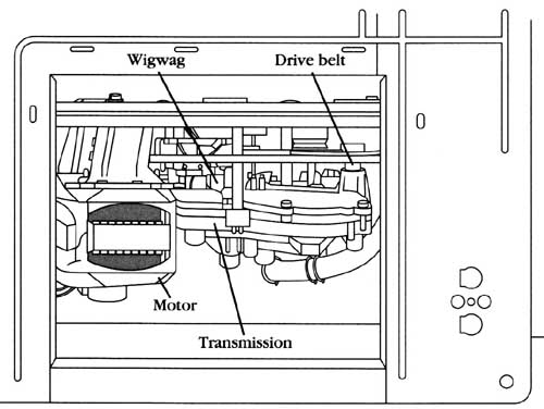
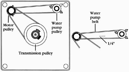
6. Remove the capacitor--Remove the capacitor from its mounting bracket. 7. Install a new capacitor--To install the new capacitor, just reverse the disassembly procedure, and reassemble. Note: a capacitor is rated by its working voltage (WV, or WVac), and by its storage capacity in microfarads (l Always replace a capacitor with one having the same voltage rating, and the same (or up to 10% greater) microfarad rating. Drive belt: The typical complaints associated with belt failure are: 1. Washer won’t agitate. 2. Washer won’t spin. 3. Washer motor spins freely. 4. Smells like something is burning. 1. Verify the complaint--Verify the complaint by operating the washer in the spin cycle. Listen carefully, and you will hear and see if the inner basket is turning, or if the circuit breaker trips. 2. Check for external factors-- You must check for external factors not associated with the appliance. Is the appliance installed properly? Does the appliance have the correct voltage? 3. Disconnect the electricity--Before working on the washer, disconnect the electricity. This can be done by pulling the plug out from the electrical outlet. Be sure that you only remove the washer plug. Or disconnect the electricity at the fuse panel or at the circuit breaker panel. Turn off the electricity. 4. Gain access to the belt -- You must gain access to the belt, either by removing the back or the front panel, or by tilting the washer, or by laying it onto its back; depending on which model washer you are working. The back panel (or the front panel) is usually held on with two screws. Remove the screws, and remove the panel. 5. Adjust the belt--Before adjusting the belt, use your finger and press on the belt; it should only deflect about 1/2 inch. To adjust the belt ( Figr. --15), loosen the motor bracket nut just enough to move the bracket. Take hold of the motor bracket, and pull against the belt just enough to take up the slack in it, and to properly re-tension it. If you are unable to adjust the tension, or if the belt is worn, replace the belt. Some models have more than one belt. One is for the drive system that is attached to the motor and the transmission pulleys. The other belt is for the water pump. This belt is attached to the motor pulley and to the water pump pulley ( Figr. --18). To adjust the water pump belt in this type of washer, just loosen the pump mounting screws and adjust to obtain the correct tension; about ‘A-inch deflection. There are even some models that use a direct drive system (which has no belts) to drive the motor, transmission and pump ( Figr. --19). This type of washer has the motor and the water pump attached to the transmission with retaining clips. Between the motor shaft and the transmission, there is a coupling. To replace this coupling, remove the retaining clips that secure the water pump and the motor. Install the new coupling, and reattach the motor and the water pump. --Water pump belt
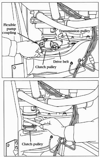
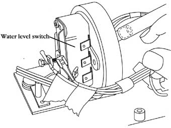
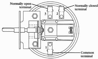
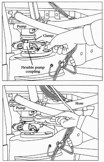
6. Replace the drive belt To replace the drive belt on this type of washer, you must remove the flexible pump coupling ( Figr. --20). Next, loosen the motor bracket nuts, and slide the motor forward to take the tension off the belt. Then, remove the belt from the motor pulley and the transmission pulley ( Figr. --21). Install the new belt on the transmission pulley and the clutch pulley. Be sure that the belt is in the pulley grooves. Next, adjust the belt tension, and tighten the motor bracket nuts. Reinstall the flexible pump coupling and clamps, be sure that the coupling is not twisted, and that it’s seated on the pump and clutch pulleys. The drive belt tension on this type of washer should be approximately ‘A inch when deflected. 7. Test the washer-- You are now ready to test the washer. Begin the wash cycle with a full load of laundry in the basket. Check the agitate and the spin cycles. If these check, reinstall outer panels. If not, readjust the belt tension. Water level control: The typical complaints associated with the water level control are: 1. Water flowing over the top of the tub. 2. Tub does not fill to the proper level selected. 3. Washer won’t agitate. 4. Washer won’t spin. 1. Verify the complaint Verify the complaint by trying to select different water levels when operating the washer through its cycles. __21 Sliding the belt over the motor pulley. 2. Check for external factors-- You must check for external factors not associated with the appliance. Is the appliance installed properly? Does the appliance have the correct voltage? Is there any physical damage to the component? Is the plastic line connected to the water level control and air dome? Check to be sure that the water is turned on all the way. 3. Disconnect the electricity. Before working on the washer, disconnect the electricity. This can be done by pulling the plug from the electrical outlet. Be sure that you only remove the washer plug. Or disconnect the electricity at the fuse panel, or at the circuit breaker panel. Turn off the electricity. 4. Remove the console panel to gain access Begin with removing the console panel, to gain access to the water level control ( Figr. --2). 5. Test the water level control To test the water level control switch, remove and label all of the wires from the switch ( Figr. --22). Remember, you will have to identify the wires according to the wiring diagram, in order to reinstall them back on the water level control switch properly. With the washer empty, use your ohmmeter (set on R x 1) and test it for continuity on the switch contacts numbered 1 and 2 ( Figr. --23). If you have continuity, This means that the water valve will be energized, allowing the water to enter the tub. Now, test for continuity between contacts 1 and 3; the ohmmeter should read no continuity. Reconnect the wires to the water level switch. Plug in the washer, and start the wash cycle. Let the console rest on top of the washing machine for this test. Be careful not to touch any live wires, or to short them to the washer chassis while the test is being performed.
As the water level rises in the tub, it forces air through the air dome and up the plastic tube to the water level control. The pressure that is exerted on the water level control’s diaphragm will trip the water level switch, from empty to full, which will start the agitation cycle. When the agitation cycle begins, turn off the washer. Pull the power plug from the wall socket to ensure that power has been removed. At this point, test for continuity again between the contacts numbered 1 and 2. The ohmmeter should read no continuity. Next, test for continuity between contacts numbered 1 and 3. The ohmmeter will read continuity. If the water level switch checks Out, then check the plastic hose that goes from the air dome to the water level control. Ensure that there are no holes or cracks in the line. If the switch checks bad, replace it. Remember this, never blow into the water level control switch to activate it. Why? You might activate the switch, but it won’t prove that the switch will activate (at lesser pressures) at the proper water level setting selected. Normally closed terminal: -- Common terminal
6. Remove the water level control To remove the water level control, remove the wires, then remove the screws that hold the component to the console panel ( Figr. --24). Next, remove the plastic hose.
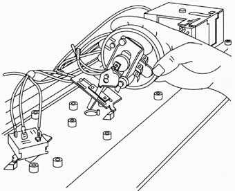
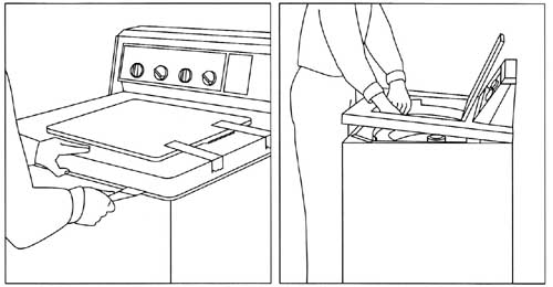
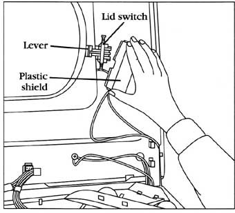
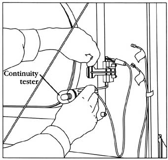
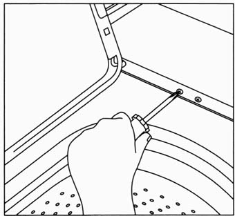
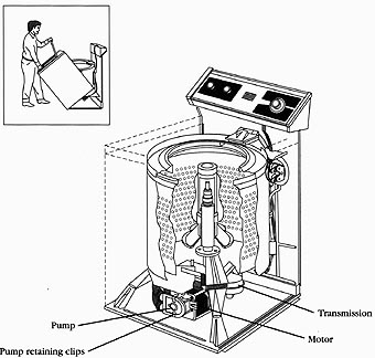
9. Reinstall the water level control. 10 reinstall the water level control, just reverse the disassembly procedure, and reassemble. Remember, you will have to identify the wires according to the wiring diagram in order to properly reinstall them back on the water level control. Lid switch: The typical complaints associated with the lid switch are: 1. Washer won’t spin. 2. Washer won’t agitate. 1. Verify the complaint--Verify the complaint by closing the washer lid, and turning the timer dial to start the spin cycle. 2. Check for external factors-- You must check for external factors not associated with the appliance. Is the appliance installed properly? Does the appliance have the correct voltage? Is there any physical damage to the component? 3. Disconnect the electricity--Before working on the washer, disconnect the electricity. This can be done by pulling the plug from the electrical outlet. Be sure that you only remove the washer plug. Or disconnect the electricity at the fuse panel, or at the circuit breaker panel. Turn off the electricity. 4. Gain access to the lid switch--If the washer’s top snaps in place, tape the lid shut. Use a putty knife to release the spring clips in each corner, and lift the top. If the spring clips won’t release, open .the lid, pull the top toward you, and lift ( Figr. --25). Raise the washer top to gain access to the lid switch ( Figr. --26). On some models, the top is held down with two screws that are se cured from underneath the top. The front of the cabinet is secured in place with two screws; take them out and remove the front panel. Then, remove the screws that hold the top in place. 5. Test the lid switch To test the lid switch, remove the two wires from the switch ( Figr. --27). With a continuity tester, test for continuity between the two terminals of the switch while moving the lid switch lever. If the switch fails these tests, replace the switch. 6. Replace the lid switch Remove the screws that hold the switch in place. Install the new switch, and connect the wires on the switch terminals. Then, reconnect the electricity and test the washer. Water pump: The typical complaints associated with the water pump are: 1. Washer won’t drain the water. Out. 2. Smells like something is burning. 3. The water in the washer won’t recirculate. 1. Verify the complaint Verify the complaint by operating the washer. 2. Check for external factors You must check for external factors not associated with the appliance. Is the appliance installed properly? Does the appliance have the correct voltage? 3. Disconnect the electricity Before working on the washer, disconnect the electricity to the washer. This can be done by pulling the plug from the electrical outlet. Be sure that you only remove the washer plug. Or disconnect the electricity at the fuse panel or at the circuit breaker panel. Turn off the electricity. 4. Access and remove the water pump In order to gain access to the water pump in this type of washer, the cabinet must be removed. Remove the screws that hold the control panel in place. Next, lift the control panel up. Then, remove the clips from each side that hold the cabinet in place. Pull back on the cabinet, and move it out of the way ( Figr. --29). With no water in the tub, remove the hoses from the pump ports (some water will spill out of the pump). Wipe the water up immediately. Check the water pump ports for any obstructions. If no obstructions are found, then disconnect the two clamps that hold the pump in place. Remove the pump. To gain access to the water pump in this type of washer, remove the back panel. With no water in the tub, remove the hoses from the pump ports (some water will spill out of the pump). Wipe the water up immediately. If obstructions are found, remove the obstructions, reconnect the hoses, and test for proper operation. If the unit is still not operating properly or if the obstruction could not be removed, then the pump must be removed. Next, remove the flexible pump coupling ( Figr. --30). Now, remove the bolts that hold the pump in place ( Figr. --31). Remove the pump. 5. Install a new water pump To install the new pump, just reverse the disassembly procedure, and reassemble. Test the washer for any water leaks. Transmission Pump Motor: Pump retaining clips: Inner basket: The typical complaints associated with the inner basket are: 1. Basket won’t spin. 2. Water won’t drain out of the tub. 3. Washer damages the clothing. 1. Verify the complaint Verify the complaint by inspecting and operating the washer. 2. Check for external factors You must check for external factors not associated with the appliance. Is the appliance installed properly? Does the appliance have the correct voltage? 3. Disconnect the electricity Before working on the washer, disconnect the electricity. This can be done by pulling the plug from the electrical outlet. Be sure that you only remove the washer plug. Or disconnect the electricity at the fuse panel, or at the circuit breaker panel. Turn off the electricity.
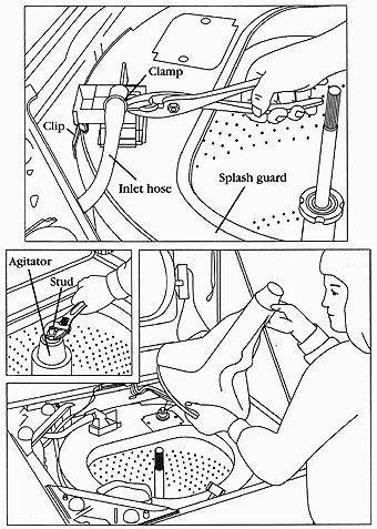
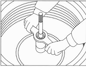
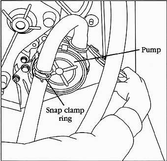
__31 Removing the pump hold down bolts. 4. Gain access to inner basket To gain access to the inner basket, you must first lift the top of the washer ( Figr. --25) and disconnect the fill hose from the water inlet, located on top of splash guard ( Figr. __32). Remove the splash guard by removing the clips that hold it to the outer tub. Now that you have more room to work with, remove the agitator. On some models, the agitator is held down with a cap and stud assembly, or the agitator might just snap onto the transmission shaft ( Figr. --33). Next, use a spanner wrench to remove the locknut that holds the basket in place ( Figr. --34). On some models, the inner basket is held in place with four bolts. If so, remove the bolts. Next, lift the inner basket out of the tub. Inspect the outer tub for debris and rust. Be sure that the tub drain opening is clear of debris. 5. Reinstall inner basket--To reinstall in inner basket, just reverse the disassembly procedure, and reassemble. One important note, don’t overtighten the locknut. Just tighten the locknut enough to secure the basket in place. If you overtighten the locknut, the washer won’t work properly. __33 Removing the agitator 6. Test washer--After you have reassembled the inner basket, splash guard, and agitator, test the washer. Check for leaks around the top rim of the outer tub. Check for agitation and spin, with a full load of clothes. Hoses: The typical complaints associated with the hoses are: 1. Washer leaks water. 2. Water won’t pump out. 3. Kinked or plugged hoses. 1. Verify the complaint Verify the complaint by inspecting and operating the washer. 2. Check for external factors-- You must check for external factors not associated with the appliance. Is the appliance installed properly? Does the appliance have the correct voltage? 3. Disconnect the electricity Before working on the washer, disconnect the electricity. This can be done by pulling the plug from the electrical outlet. Be sure that you only remove the washer plug. Or disconnect the electricity at the fuse panel, or at the circuit breaker panel. Turn off the electricity. 4. Remove defective hose To remove the defective hose, the tub must be empty of water. Loosen the clamps that hold the hose in place. On some models, the manufacturer uses a snap ring clamp. To remove this type of clamp, just squeeze the ends together ( Figr. --35).
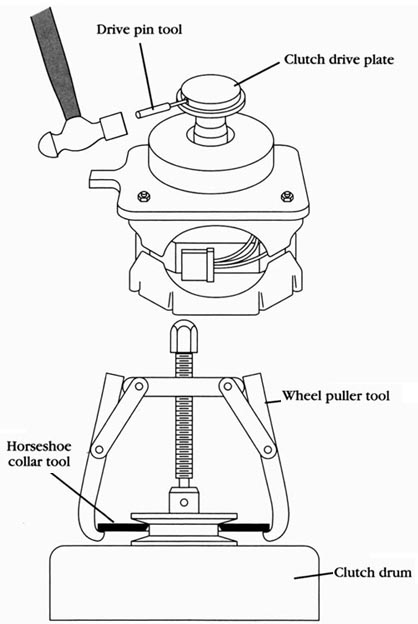
--Clutch The typical complaints associated with the clutch are: 1. Washer won’t agitate. 2. Washer won’t spin. 1. Verify the complaint -- Verify the complaint by operating the washer. 2. Check for external factors -- You must check for external factors not associated with the appliance. Is the appliance installed properly? Does the appliance have the correct voltage? 3. Disconnect the electricity -- Before working on the washer, disconnect the electricity. This can be done by pulling the plug from the electrical outlet. Be sure that you only remove the washer plug. Or disconnect the electricity at the fuse panel, or at the circuit breaker panel. Turn off the electricity. 4. Gain access to the motor -- To gain access to the motor, the back panel must be removed. The back panel is held on with screws. Remove the screws, and remove the panel. 5. Remove the motor and clutch -- In this type of washer, to remove the motor and clutch assembly, you must first disconnect the wires of the motor from the wiring harness. Then, remove the flexible pump coupling ( Figr. --30). Remove the belt from the clutch. Once the motor is isolated, remove the three bolts that hold the motor mounting plate to the suspension. Now, remove the motor assembly from the washer. You are now ready to remove the clutch assembly. Remove the clutch drive plate by removing the roll pin. This is accomplished by using a drive pin tool on the roll pin ( Figr. --36) and hitting it with a hammer. On a stubborn clutch drive plate, the use of a wheel puller tool and a horseshoe collar tool, will make it easier to remove ( Figr. --37). Disassemble and remove the clutch assembly, and replace with a new assembly. Clutch drive plate:
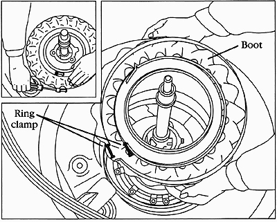
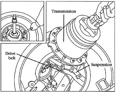
Horseshoe collar tool; Clutch drum __37 Use a horseshoe collar tool to remove a stubborn clutch drum. 6. Install new clutch assembly To install the clutch assembly, just reverse the disassembly procedure, and reassemble. Adjust the belt tension. 7. Test the washer Test the washer operation by running the washer through a cycle. Be sure that you have some clothes in the washer when testing it. Transmission: The typical complaints associated with the transmission are: 1. Washer won’t agitate. 2. Washer won’t spin. 1. Verify the complaint Verify the complaint by operating the washer. 2. Check for external factors You must check for external factors not associated with the appliance. Is the appliance installed properly? Does the appliance have the correct voltage? 3. Disconnect the electricity Before working on the washer, disconnect the electricity. This can be done by pulling the plug from the electrical outlet. Be sure that you only remove the washer plug. Or disconnect the electricity at the fuse panel or at the circuit breaker panel. Turn off the electricity. 4. Remove inner basket. To remove the inner basket, see the section labeled: Inner basket. 5. Remove the transmission boot To remove the transmission boot, loosen the ring clamps and lift the boot off the transmission and the outer tub ( Figr. --38). Examine the boot, if it’s damaged, replace it. If the ring clamps are rusted, replace them. 6. Remove the transmission Remove the six bolts that hold the transmission to the washer’s suspension. Remember the position that the transmission is in before you remove it. This will help you later for the reinstallation of the new transmission. Next, reach in and remove the drive belt from the transmission pulley. Lift the transmission out of the washer ( Figr. __39). 7. Install the transmission To reinstall the transmission, just reverse the disassembly procedure, and reassemble. Don’t forget to reinstall the belt. 8. Test the washer Test the washer operation by running the washer through a cycle. Be sure that you have some clothes in the washer when testing it.
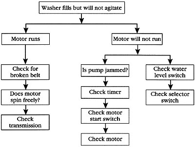
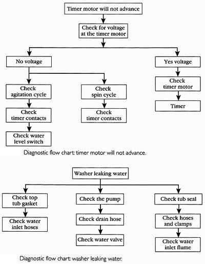
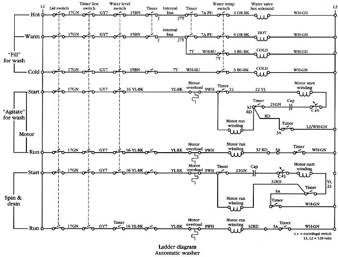
DIAGNOSTIC CHARTS The following diagnostic flow charts will help you pinpoint the likely causes of the problem (Figs. __40, __41, and __42). __40 Diagnostic flow chart: washer fills, but won’t agitate. The wiring diagrams in this section are used a
Prev: Automatic Washer--part 1 Next: Automatic dryers Home top of page All related articles |
