---

----- Useful for much more than sawing curves. A bandsaw is unsurpassed for
ripping thick or warped stock and can be effectively used for cutting dove
tails and tenons.
My first encounter with a bandsaw was disappointing. The saw was a small Sears Craftsman made in the 1950s that arrived in my shop as part of a package deal on several used power tools. I could never get the machine to cut well, and blades snapped regularly. I rarely used it and after a few years I sold it. I was convinced that bandsaws were cranky tools of limited use to anyone not making jigsaw puzzles. Since then I've learned how to set up and use a bandsaw, and I'm sorry I sold that little machine. It was very well made, and with the right blade and a tune-up, it would have been a real asset.
A bandsaw is much more than a specialty tool for cutting curves. It can cut tapers without the use of jigs, and it is an excellent tool for ripping lumber, rivaling a table saw. It offers great depth of cut and zero chance of kickback, no matter how gnarly the stock.
For joinery, a bandsaw makes short work of roughing out dovetails and sawing tenons. In many cabinet shops, the saw's main use is for resawing, cutting a thick board into several thinner ones. Resawing makes efficient use of expensive or highly figured wood, and it makes it easy to match grain. In fact, a careful furniture maker can sometimes cut all of the most visible elements in a piece of furniture from a single board.
Bandsaws are complex machines. They have more moving parts and adjustments than any other three power tools combined, and they are unforgiving of misalignments and poor maintenance. Despite their complexity, however, properly setting up and tuning a bandsaw is not difficult, just time consuming. Once the saw is working well, its versatility will be an ample reward.
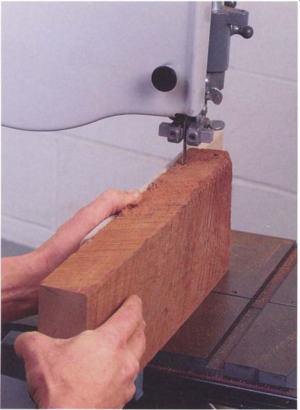
----------- An ability to re-saw thick stock greatly expands furniture-making
options.
Anatomy
The thin ribbon of steel that forms the blade of a bandsaw must be pulled very taut to cut properly. The tension on a 1.25-in. blade can exert almost 1,000 lb. of stress on the frame of a bandsaw, so to resist this force, the frame must be sturdy. In large saws, the frame is made of cast iron, whereas smaller benchtop models are often made from die-cast aluminum. Several companies build their bandsaw frames from steel plate.
The popular, and often imitated, Delta 14-in. bandsaw has a two-piece cast-iron frame that bolts together at the bottom of the back post. You can increase its cutting capacity by installing a riser block between the upper and lower castings.
THE WHEELS
At the heart of a bandsaw are the wheels that the blade travels around.
Made from steel plate or cast aluminum or iron, they can run from a petite 6 in. to a behemoth 10 ft. or more in diameter. Wheels measuring 14 in. to 24 in. are typically seen in cabinet shops. On better-quality machines, the wheels are carefully machined and balanced to eliminate vibration.
The rims of the wheels are covered by a rubber tire a fraction of an inch thick. On most machines, the tire has a slight curve in its surface, called a crown, making it higher in the middle (see the illustration at right). A crowned tire helps to pull the blade to the center.
Most saws use a pair of wheels, but occasionally you may find a three wheeled machine. A third wheel increases the clearance to the back post while keeping the overall size of the machine small. The additional clearance is useful when swinging stock to cut curves. The trade-off is that three-wheelers can't handle the wide blades and higher tensions needed for resawing thick stock. These machines also can be harder to align properly and are more likely to have the blade crack from metal fatigue, a problem with all machines that have small wheels.
MOVING THE BLADE
On all saws, the lower wheel is driven by the motor. Some machines use a pulley and belt-drive system, while others use a direct drive, where the lower wheel is mounted directly on the motor's shaft. The axle of the upper wheel is mounted on a casting that slides vertically in the frame to tension the blade. The tension is controlled by a heavy spring compressed by a nut on a threaded rod, and the degree of tension is typically shown on a calibrated scale (see the top photo on p. 140). A second adjustment allows the upper wheel to be tilted several degrees to either side of vertical. This is called tracking, which along with a crowned tire keeps the blade centered on the face of the tire (see the illustration on p. 140).
--------------
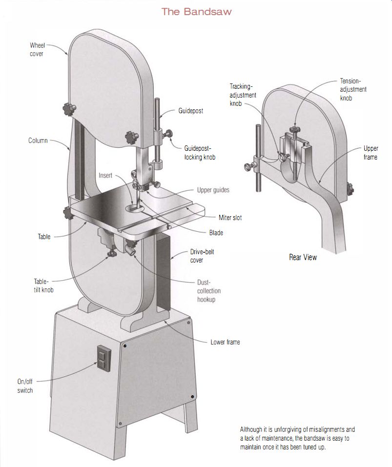
The Bandsaw
-----
Although it is unforgiving of misalignments and a lack of maintenance, the bandsaw is easy to maintain once it has been tuned up.
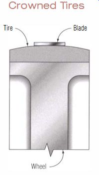
------------- Crowned Tires ---- Although it seems counterintuitive, a bandsaw
blade will stay centered on a tire with a slight crown.
---------
Cooling the Motor
Until recently, most consumer model bandsaws were under-powered, equipped with motors of only 1/2 hp or 3/4 hp. Newer saws have 1-hp motors, but this may be inadequate if you plan to re-saw wide planks.
If you do upgrade to a larger motor, buy a totally enclosed fan-cooled (TEFC) motor, which won't become plugged up with sawdust and overheat.
----------------
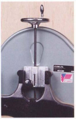
----------- Blade tension is controlled by the handwheel at the top of
the vertical rod. The knob below it is used to adjust blade tracking.
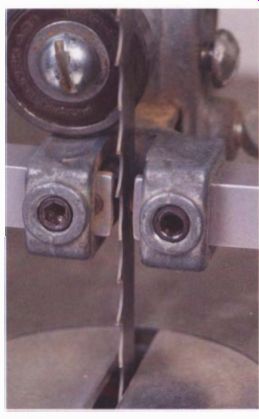
--------- Solid blocks in this guide assembly support the sides of the
blade; a bearing supports the back as pressure is applied during a cut.
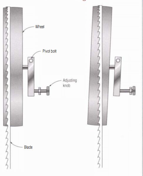
------ Blade Tracking ----Tilting the upper wheel with the tracking control
brings the blade to the center of the wheel's rim.
GUIDING THE BLADE
To stabilize the blade, guide assemblies are mounted above and below the table (see the bottom photo on p. 140). The upper guide is on an adjustable post so the guide can be positioned just above the surface of the board. Guides support the blade on both sides and on the back edge.
The back support is called the thrust bearing, which is typically a ball bearing, although some European machines use a steel disk running in a sintered-bronze bearing. Depending on its design, the blade can run against either the side or the face of the thrust bearing. On better-quality guides, the bearing is covered by a hardened steel face to resist wear.
The two side supports can be either ball bearings or blocks of various materials that simply pinch the blade between them. Ball bearings need less daily maintenance than blocks, but they can still wear out. They also are fussier to adjust and may need frequent cleaning when cutting woods that contain a lot of pitch.
Block-type guides (see the sidebar on the facing page) offer simplicity, easy maintenance, and excellent blade support. They are used on both consumer- and industrial-grade machines. Several suppliers sell aftermarket ball-bearing guide assemblies to replace block guides, but they generally don't improve a saw's performance and may, in fact, degrade it if not carefully adjusted.
For angled cuts, a bandsaw's table tilts on curved supports called trunnions. On many saws, the table tilts to both sides of vertical, which is useful when cutting dovetails.
--------
Blade Guide Blocks
GUIDE BLOCKS COME IN A DOZEN DIFFERENT MATERIALS, and each supplier claims its own brand is the best. In reality, almost all blocks will work well if their faces are kept flat and square and they are adjusted to a close fit on the blade. Blocks fall into two main categories: hard types, which are made from steel or ceramic, and soft types, which are made from brass, wood, or plastic.
Hard blocks have one main advantage: Their faces stay flat because they wear slowly. This allows you to set them once and then do a lot of sawing without having to readjust or reface them. They also have two disadvantages. First, they are more difficult to reface once they have become grooved. Second, they will ruin your blade instantly if they strike the teeth. Hard blocks are best used on wide blades where they can stay well clear of the blade's cutting edge.
Some suppliers claim that hard blocks create so much friction that they overheat and damage the blade, but I doubt it. Far more heat is generated by the friction of sawing. Steel blocks come as original equipment on many saws and, as long as you are careful, they give excellent service. I set hard blocks to bear very lightly against the side of the blade and then rotate the full blade through them by hand to make sure that a bad weld or kink won't cause jamming.
Soft blocks come in a wide variety of materials. They will not damage the blade's teeth, and they support the blade well because they can be fitted tightly-right around the teeth on very narrow blades. The softest of them are made of pure plastic, probably a nylon, and wear far too quickly to be practical. I've also read reports suggesting these soft blocks can melt and gum up the blade. A composite block called Cool Blocks work better and won't melt, but they still wear rather quickly.
Brass or bronze both make excellent block material and strike a good balance between wear resistance and ease of refacing. They are easy to file fiat when they develop grooves. These are used on larger machines, but I am not aware of anyone supplying soft metal blocks for smaller Delta-style saws.
Wood blocks are my favorite. They wear well, are easily replaced for free from the scrap box, and can be made up by the dozen quickly. This last point is a big advantage. Any time the block is worn in the slightest, you can just throw in a fresh set and get back to work quickly.
-----------
Understanding Blade's Bow
A bandsaw only cuts well when its blade is perfectly straight, and almost all cutting problems with the saw are a result of the blade bowing under the stress of sawing. To understand the dynamics of bowing, try a small experiment. Cut a %-in. by 6-in. strip of paper and pull it taut between your hands. Reaching with a finger, apply pressure to the edge of the strip at its midpoint and notice what happens. The strip refuses to bow straight back; it flexes sideways in a broad curve.
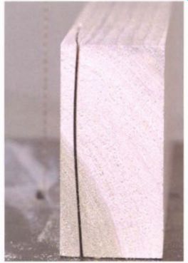
---------- A barrel-shaped saw kerf is the trademark of a blade that bows
under pressure during a cut. A sharp blade of the right type and the correct
tension will correct the problem.
------------
Choosing a Blade
THERE'S A LOT TO CONSIDER WHEN CHOOSING A BLADE, most important of which is blade width. If you aren't going to be cutting a curve, choose the widest blade your saw can tension properly. That may be only a 0.5-in. blade on home-shop saws. Industrial machines may be able to handle blades of up to a couple of inches. For curved patterns, you'll need a narrower blade. A 3/8-in. blade typically can turn a curve with a radius of 1.5 in., but any cut will go easier if you don't push a blade to its limit.
Next in importance is the number of teeth per inch (tpi), which is also called pitch. A good rule of thumb is to keep from 6 to 12 teeth in contact with the stock while you cut. Choose a coarser blade for fast cutting and a fine blade for a smoother cut. Softwoods are best cut with a coarser blade because it clears the sawdust better.
Some top-of-the-line blades have a variable pitch, meaning the teeth are alternately closer and farther apart to prevent the blade from developing a steady vibration that produces a rougher cut. A typical tooth spacing on a variable-pitch blade is marked as 2/3 pitch, which means 2 to 3 teeth per inch. A skip-tooth blade achieves a wider tooth spacing with small teeth by leaving out every other tooth.
The face of a saw's teeth can either be cut square to the blade, a 0-degree rake, or hooked with a positive rake of 10 degrees or more.
Hooked teeth cut faster but rougher than standard or skip-tooth blades, which are sharpened with a 0-degree rake.
The last decision about a blade is the metal it is made from. This is as much a pocketbook decision as it is a technical one. Carbon-steel blades are the least expensive. They cut well but dull quickly if they get hot. These blades are best for light cuts in softer woods; don't expect to rip rosewood with them.
Bimetal blades have teeth of high-speed steel, whereas the main part of the blade is ordinary steel. High-speed steel won't dull like carbon steel when it gets hot, and the teeth will stay sharp much longer when cutting dense hardwoods. Bimetal blades cost considerably more than carbon-steel blades, but their longer life span-makers claim 10 times longer-make them more economical over time.
Carbide-tipped blades for smaller band saws are just becoming popular. At more than $100 a blade, they would appear to be a luxury, but for resawing wide hardwood boards, they do cut superbly fast, smooth, and straight. If you intend to do a lot of resawing in difficult woods, they are worth the investment.
--------------
Troubleshooting
Bandsaws are susceptible to three problems: poor-quality cuts, vibration, and poor blade tracking. Most cutting problems can be solved by choosing the correct blade and fine-tuning the saw; vibration and tracking problems usually require repair or replacement of parts.
Under the pressure of cutting, a bow can form in a bandsaw blade.
Several things, all of them bad, result. First, the sides of the kerf take on the sideways bow of the blade, the infamous barrel-shaped cut that appears when sawing thick stock (see the photo at left). Second, the blade repeatedly wanders to one side and then pulls back in. This makes it very difficult to follow the intended line of the cut, and it creates a washboard surface on the face of the board. Third, the bowed blade binds in the cut, increasing the load on the motor and overheating the blade.
A couple of things can help. For straight cuts, always use the widest blade your saw can tension properly. For sawing curves, use the widest blade that will negotiate the tightest curve in your pattern. The type of teeth on the blade, their spacing, and sharpness also are critical (see the sidebar on the facing page). The wrong blade or a dull blade will need higher feeding pressure, which makes the bowing problem worse.
----------
Give the Springs a Rest
Tension springs weaken with use, but they last longer if you reduce the tension on the blade when the saw isn't being used. To prevent the blade from slipping off the wheels, don't completely remove the load from the spring. Just back it off to the lowest setting on the tension gauge.
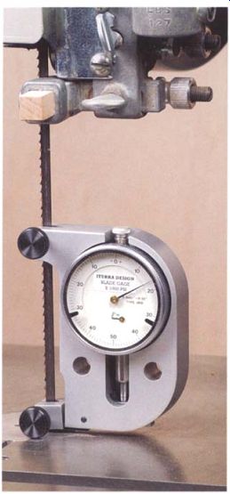
------------ Although very accurate, blade tension measuring devices are
too expensive for most home shops.
A Simple tool to tension Bandsaw Blades
A FEW HARDWOOD SCRAPS, TWO NAILS, and a little time are you'll need to make a blade-tensioning device that is surprisingly accurate on any width and any type of blade.
The idea is simple: Blades stretch slightly as they are tensioned. By measuring the gap between the two halves of the device as blade tension is increased, you can determine just how tight the blade is. This approach is much more accurate than using the tension scale built into the saw-and much cheaper than buying a tension measuring device that does essentially the same thing.
------------
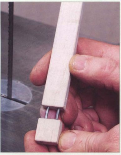
1. Made from a scrap of hardwood and two finish nails, this simple gauge allows accurate tensioning of a bandsaw blade by measuring how much the blade stretches. Start with a scrap of fine-grained hardwood 3/8 in. by 3/4 in. by 5 3/8 in. long.
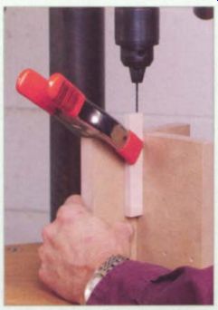
2. In one end of the block, drill a 3/32-in. hole as deep as the bit will
allow for the alignment pin.
Clamping the block upright on a shop-made V-block makes it easy to drill the hole accurately.
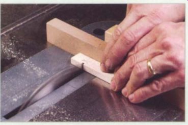
3. Before making a cut, make index marks on both sides of the cut line so
you can line up the two pieces in their original orientation. Carefully cut
a %-in. long piece from the drilled end of the block, then polish the cut face
of the smaller block by running it across very fine sandpaper on a flat surface.
--------
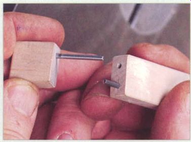
4. With a 3/32-in. bit, drill a second hole 1/2 in. deep in the end of the long block next to the alignment pin hole.
Make the measuring pin by cutting a 6d finish nail 1 5/8 in. long. To prevent snagging the feeler gauge, slightly round the working end of the pin and tap the pin into the hole you drilled for it. An alignment pin 1 5/8 in. long, also cut from a 6d nail, fits in the other hole.
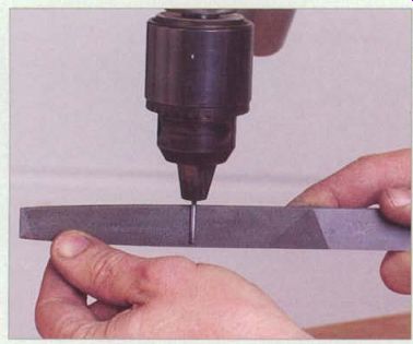
5. Before inserting the alignment pin, file one end slightly to reduce its diameter and allow it to slide easily. Chucking the pin in a drill press is an easy way to file it, but don't take off too much material.
--------
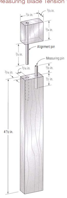
Measuring Blade Tension ---This shop-made device consists of two
finish nails and a small block of hardwood, but it accurately measures blade
tension on a bandsaw.
----------------------
BLADE TENSION
A critical element that affects blade stability is tension. For demanding work, such as resawing, blade makers recommend that a blade be tensioned to 30,000 lb. per square inch (psi) of its cross section, which translates to a pull of 375 lb. on a 0.5-in.-wide blade 0.025 in. thick. The saw's frame, bearings, and wheel will actually have to cope with twice that load because both the cutting and returning part of the blade are equally taut.
Most home-shop-grade tools simply can't sustain this much strain without damage, and their springs and tensioning scales will often limit you to less than a quarter of the recommended tension. Manufacturers generally recommend blades on these machines be tensioned to a maximum of 15,000 psi. A complicating factor is that the tension spring weakens with use, making it even harder to properly tension the blade. Replacing the spring every few years is the only solution.
There is no simple way to measure blade tension, since tension gauges built into the bandsaw aren't very accurate. The best way to gauge the tension of a blade is to measure how much the blade stretches as it is tightened. The amount is small, but a 5- in. length of blade will stretch 0.001 in. for every 6,000 psi of tension that is applied. Starrett® and Lenox® both sell gauges that measure how much the blade stretches when it's being tightened, but they cost several hundred dollars (see the photo at right). The easiest approach for home-shop bandsaws is to tension the blade to a higher setting on the saw's built-in scale. In other words, tighten a 1/2-in. blade to the 3/4-in. setting. It is not a good idea, however, to exceed the highest tension setting on the saw's scale. Too much tension may crush the spring, which limits its role as a shock absorber, and can cause wheel and bearing damage.
Another option is to make a simple device that measures blade tension (see the sidebar on pp. 144-145). You can make this tool in an hour from a scrap of hardwood and two nails. It attaches to the bandsaw blade with two clamps 5 in. apart. As the blade is tensioned, the gap between the upper and lower halves of the tool increases, so you measure the change by slipping a feeler gauge between the measuring pin and the lower block. A second pin goes into both blocks to keep the two parts of the assembly lined up. The tool works on all blade widths.
Using the tool is simple. Install a blade on your bandsaw, tension it lightly, then adjust the tracking and the guides while moving the blade by hand. Once the blade rotates properly, power up the saw and let it run for a minute or two to warm up the blade and tires, then cut the power and unplug the saw. Next, back off the tension until there is just enough pull on the blade to prevent it from going slack and slipping off the tires; normally this will be a little below the tension mark for a 1/8-in. blade on the machine's scale.
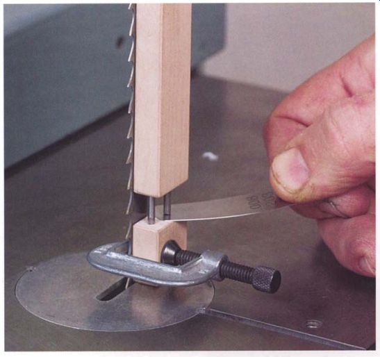
---------- With the gauge clamped to the blade and tension increased, a
feeler gauge measures the gap under the pin. Each 0.001 -in. increase in the
gap indicates an additional 6,000 psi of tension.
Raise the upper blade guide out of the way, and lightly clamp the jig to the side of the blade just behind the teeth. The measuring pin should be toward the back of the blade. Loosen the upper clamp and pinch a 0.005-in. feeler blade between the measuring pin and the lower block. Leaving the gauge in place, tighten both clamps.
Next, pull out the feeler gauge and recheck the gap. It may change slightly from the torque of the clamps, but it isn't important that it be exactly 0.005 in. Using the gauge set, find and note which gauge just slides between the pin and the block.
To tension the blade, begin by choosing a feeler gauge the width of the starting gap plus an additional 0.001 in. for each 6,000 psi of tension you want to place on the blade. For 15 ,000 psi of tension, add 0.003 in. to the initial gap, which will get you to 18,000 psi. Once there, you can back off the saw's tension adjustment a little to get in the neighborhood of 15,000 psi.
With the correct feeler gauge in hand, increase the blade tension while checking the gap under the pin. When you reach the correct tension, the gauge will slide under the pin. Mark your saw's tensioning scale at its pointer, noting the width of the blade. The recalibrated scale will allow you to quickly tension the same width blade in the future without using the tool every time.
If you build this tool and try it on any small, consumer-grade machine, such as the Delta 14-in. saw or its numerous clones, you will probably discover that the saw can't even come close to the recommended 15,000 psi tension. With a 1/2-in. blade in the saw, you are likely to find that running the indicator up to the J,;-in. blade setting increases the gap by only 0.001 in. (6,000 psi) or not at all.
Replacing the Spring ---- If your saw can't reach 15,000 psi of tension, it's because the spring on the machine has been crushed. It will exert far less pressure than it was originally designed for, no matter how far it is compressed. All you can do is buy a new spring, preferably one of the better-quality aftermarket ones made by Iturra Design of Jacksonville, Florida, which you can call at (888) 722-7078. Made from a better grade of steel, and more of it, the Iturra spring won't weaken over time.
ADJUSTING GUIDES AND BLOCKS
Shortening the length of the blade between the guides to a minimum also will reduce bowing. Always set the upper guides so they are close to the surface of the stock. You can't adjust the lower guides, but the best designed machines have them tucked up close to the underside of the table. Block guides often work better because their compact design allows them to move in closer to the stock than the bulkier ball-bearing guide assemblies.
Of course, the most basic adjustment may be the most important to prevent bowing: Make sure the guide blocks fit tightly to both the sides and the back of the blade. And, here again, simple block-type guides often work better than ball bearings, which need to be set a bit looser to cut down on noise and wear. You should check blocks regularly for wear and resurface them as needed. In this regard, wood blocks are easy to service because the tools and materials for fixing and replacing them are always at hand.
Wood guide blocks are simple to make and work very well. The ideal material for the guides is lignum vitae, a dense tropical wood with natural oils that was used extensively as a bearing material in old machinery. A good substitute is hard maple with an added lubricant, such as DriCote® spray-on blade and bit lubricant made by Sandaro Industries. It is commonly available from many woodworker-supply companies and it works very well in this application. Simply cut the wood to the right size, then spray the bearing end of the block before you install it in the guide holder.
Other than poor cutting, the most common problem with a bandsaw is vibration. In addition to the usual suspects-bearings, belts, and pulleys wheels and especially the tires are often at fault. A wheel can be warped because the casting was badly done or because it was bent in shipping or by severe over-tensioning of the blade. A second source of vibration is poorly balanced wheels, which is fairly common on low-budget machines.
On occasion, a well-balanced wheel can be thrown off by clumps of gummy sawdust packed onto the inner surface of the rim. A buildup of sawdust and pitch on the surface of the tire also can lead to vibration.
And, as a machine gets older, the tires can harden, crack, and eventually break away, leading to moderate to severe vibration.
A final problem with band saws is the failure of the blade to track correctly. It may wander or walk entirely off the rim while cutting. This is usually due to grooves in the tire or wear that reduces the crown profile.
Tracking problems also can be caused by looseness or binding in the upper axle and tracking assemblies or by large misalignments between the upper and lower wheels.
Set Up, Then Tune Up
Tuning up a bandsaw is very different from tuning a table saw. On a table saw, you should check adjustments for square and parallel a few times a year; in between, very little needs to be done. On a bandsaw, you only have to do a number of adjustments and minor repairs once, in a process called setting up the machine. Afterward, you'll make small adjustments on an almost daily basis, similar to a musician tuning up an instrument each time he plays. The main purpose of the setup is to make the various controls for adjusting the saw work so smoothly and reliably that daily tune-ups are effortless.
The best approach is to tackle one part of the bandsaw at a time.
Although the machine may appear complicated, its individual components are fairly simple. Take your time, keep track of the parts, and take notes or make a sketch to help with reassembly.
The setup procedure tackles parts of the machine in the following order:
• Bearings, belts, and pulleys
• Wheels and tires
• Upper wheel tension and tracking assembly
• Frame joint
• Table trunnions
• Lower blade guides
• Wheel alignment
• Guidepost and table alignment
At each step, you'll be cleaning and smoothing parts, removing paint, applying grease and oil, and adjusting alignments. Much of this may seem tedious and trivial, but the end result will pay off.
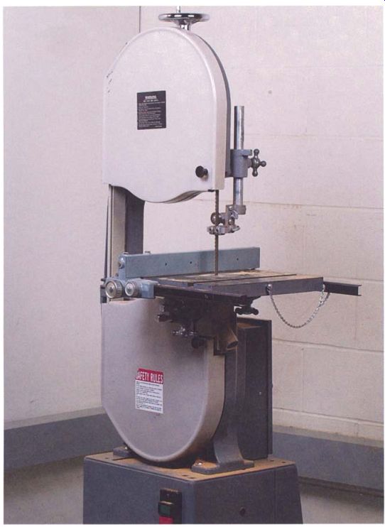
--------- Widely imitated, the Delta 14-in. bandsaw has been in production
since the 1930s with only minor changes.
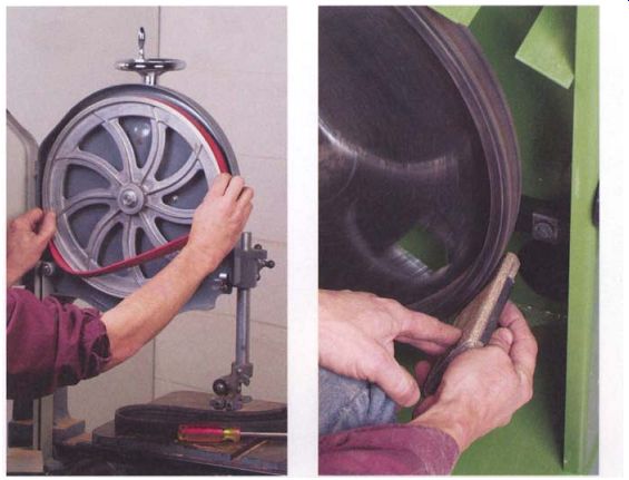
-------- On some saws, tire replacement is easy: The tire just snaps into
a groove in the wheel rim. Replacements on other saws, however, must be glued
on.
---------- Sanding the outer edges of a tire can restore the crown and correct blade-tracking problems. Tires on Delta-style saws are thinner and should not be sanded.
The bandsaw I've used to explain the process is a Delta 14-in. model, a tool that has been in continuous production for more than 60 years with only minor design changes. This saw, and its Taiwanese clones, is by far the most common bandsaw in woodworking shops. The Delta is well designed, but it can be greatly improved by going through the following setup and tuning procedures. If you have a European or industrial-grade saw, some of the steps may not be needed, but any bandsaw will benefit from cleaning, lubricating, and aligning.
Setting Up a Bandsaw
Begin by unplugging the saw and removing the blade. Check the motor, belts, pulleys, and bearings for problems. Sight and hearing will give you many cues. A misaligned pulley makes a lot of noise, and you can actually see the excess vibration in the pulley as the saw runs.
WHEELS AND TIRES
Carefully examine the condition of the tires on each wheel. Using an abrasive pad, remove any sawdust and gum. The combination of heat and pressure from the sawblade can make the sawdust adhere tenaciously, but don't use solvents: There is a chance they will damage the rubber.
The tires should be smooth and flexible, without any cracks or grooves in the rubber. If the tires have deteriorated, you'll have to replace them, which is easy on Delta-style saws. The tire sits in a groove machined in the wheel's rim, so the tire just snaps into place (see the photo at left above). On most other saws, you'll have to glue the new tire onto the rim with rubber cement or auto weather-strip adhesive.
Most tires should have a crown of about 1/32 in. , although some large saws designed to use wide blades have flat tires. If the crown is worn away but the tires are otherwise in good shape, you can restore the crown by sanding it. To restore the crown on the lower tire, run the wheel under power, with the blade removed, while holding a sanding block against it.
Pivot the block to create the right shape (see the photo at right on the facing page). To restore the upper tire, have a helper spin the wheel either by hand or by holding a sanding drum chucked in an electric drill against it while you work with the sanding block. Sanding rubber will create an obnoxious black dust, so try to keep it out of the air by picking it up with a shop-vacuum hose held next to the block while you sand.
On Delta-style machines, however, don't try to restore the crown by sanding; the tire is too thin. There is a crown profile machined into the wheel's groove, so replacing the worn tire solves the problem.
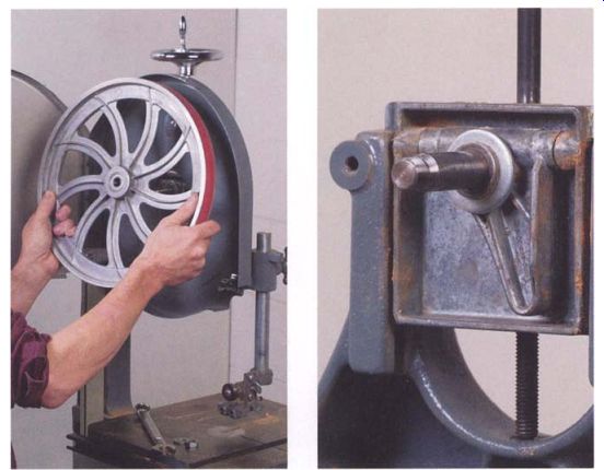
------------ To check and lubricate the tension and tracking controls,
you must first remove the saw's upper wheel. A nut at the end of the axle holds
it in place.
The tension and tracking assembly is made up of only a few simple parts, but they must work very smoothly if the saw is to perform properly.
Controls ------- The tensioning and tracking control handles on some bandsaws are small and awkwardly located. After market suppliers offer replacement handles that are better designed and much easier to use.
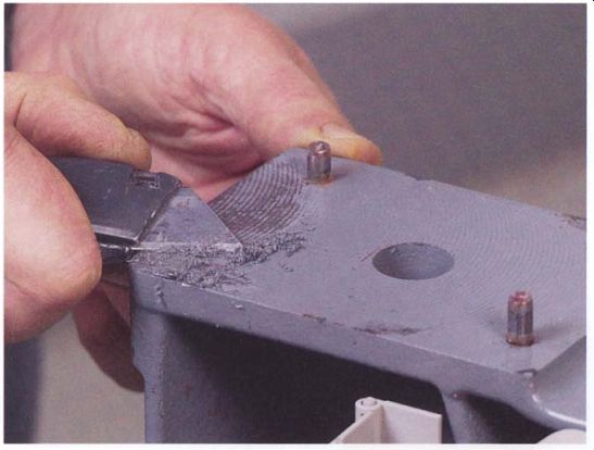
---------- Removing the paint from the machined surfaces at the joints
of a saw's frame will dampen vibration and make it easier to align upper and
lower wheels accurately.
TENSION AND TRACKING CONTROLS
To service the tensioning and tracking controls for the upper wheel, the wheel must come off (see the photo at left below). Slide it off its axle after unthreading the nut on the end of the shaft (keep track of all the washers and where they go). Remove the wheel cover, then slide the entire axle assembly out of the grooves in the saw's frame. Clean off the old grease and pass a file over the sliding surfaces to remove any rough spots, then examine the small casting that the axle is attached to, making sure it isn't cracked or bent. On Delta-style saws, the axle may be a very loose fit in the casting but this is normal; the tension on the blade will tighten it up.
If you find any paint in the grooves of the saw's frame, which is not uncommon, you should scrape it out using the tip of a utility knife, then finish up with a pass or two of a file. Paint in the grooves will make the tension control bind and cause the saw to perform erratically.
If the saw is more than two or three years old or if it has seen a lot of use, this is a good time to replace the tension spring. The spring weakens dramatically over time, making it impossible to properly tension the blade.
The last thing to do before reassembly is to round off the end of the threaded tension rod and the smaller track-control rod so that they turn smoothly. Apply oil to the hinge pin of the tracking mechanism and use grease or stick lube on all of the sliding and threaded parts before sliding the axle assembly back in the saw frame. The ball bearings in the wheel hub are typically sealed and can't be lubricated.
Before reinstalling the upper axle assembly on Delta-style saws with two-piece frames, consider unbolting the upper frame casting from the base casting and scraping the paint off their mating surfaces (see the photo above). Paint between the two parts throws off the alignment of the bandsaw, and it also "softens" the joint, making the saw more likely to flex and vibrate under load. This problem is even worse if the machine has a riser block because there will be a corresponding increase in the paint layers between all the parts.
UPPER BLADE GUIDES
Remove the guide blocks or bearings and check their condition. The bearing surfaces of blocks should be smooth and square, so grind, sand, or replace them as needed (see the photo at left below). While the blocks are out, check that the metal casting in which the blocks are mounted hasn't been distorted or cracked from overzealous tightening of the set screws. It may need to be replaced.
Any ball bearings used in the guide should turn smoothly, without any grittiness. You can try to free tight bearings using a dose of light machine oil, but any success may be short lived and the bearing probably will have to be replaced. If the front face of the thrust bearing is badly chewed up, replace the bearing. Clean off any pitch and sawdust on the rim of the bearings using penetrating oil and abrasive pads.
Next, clean up the threads of all the thumbscrews or lock bolts in the guide assembly and slightly round their tips so they'll hold better and adjustments won't creep as they're tightened. Use lubricant on all of the moving and threaded parts of the guide as you reassemble it.
On Delta-style saws, if you look at the end of the hex-shaped rod that supports the thrust bearing, you'll see that the bolt hole is off center.
Install the rod in its socket so that the center of the bearing is as far as possible from the blade. The blade should touch only near the rim of the bearing (see the photo at right below).
Replacement Ball Bearings ------- Ball bearings are made in hundreds of standard sizes, so look on the side of the bearing you want to replace for a number code. Instead of getting replacements from the tool's manufacturer, it's often quicker and cheaper to go to a local bearing-supply house, where the part also may be of better quality. When buying, always order sealed rather than shielded bearings.
A sealed bearing does a much better job at keeping out dust, which will make the bearing last longer.
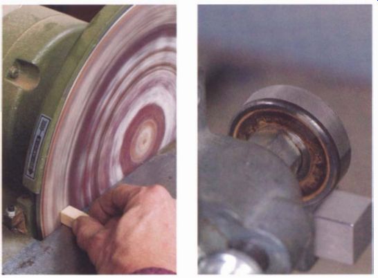
----------- Refacing worn guide blocks is easy if they're made from a soft
material such as wood. Faces should be flat and square to the sides.
The upper thrust bearing on a Delta-style saw is mounted off center on the end of a hex-shaped rod. Install the rod so the center of the bearing is as far away from the blade as possible.
-------- Paint on the mating surfaces of the table trunnions may cause
binding. Rarely serviced, the trunnions work much better after they are cleaned
and lubricated.
Clean up the guidepost and remove any burrs on it using a file. If needed, shape the end of the post-locking screw to fit the groove of the post so it will hold better. Later, when a blade is installed, the position of the guide assembly on the end of the rod will be adjusted to center it on the blade.
TABLE TRUNNIONS
On smaller saws, the next step is to remove the table by unthreading the handles on the bolts that lock the trunnions. The table should then lift right off.
From the underside of the table, unbolt the upper halves of the trunnions. This will allow you to check how the heads of the lock bolts fit inside their grooves in the trunnion castings. Often they will fit poorly and the soft metal on the inside of the castings will be chewed up. Spend a few minutes using a file to clean up the damage and get the bolt heads to fit properly. Use a stick lube on the bolt heads and all of the sliding surfaces when you reassemble the trunnions.
Bolt the trunnion upper halves back on the table but leave the bolts slightly loose. You should tighten them up only after you replace the table on the saw's base and the upper and lower halves of the trunnions are mated.
On larger saws, the table can weigh several hundred pounds, so it makes a lot more sense to work on the trunnions with the table in place. If the curved surfaces of the trunnions are painted, carefully scrape the paint off and polish the bearing surfaces with emery paper.
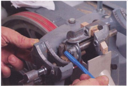
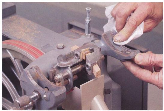
--------- Bathed in sawdust and resin, the lower blade guide needs occasional
cleaning and lubrication to keep it working smoothly.
LOWER BLADE GUIDES
Before replacing the table, you should work on the lower blade guide assembly while it is easy to get at. As with the upper guide, check and repair or replace the blocks and bearings as necessary. If the table is in place, tilting it will often improve your access to some parts of the lower guides.
The mechanism that adjusts the lower guides on Delta-style saws is a bit complicated, so take it apart for a thorough cleaning only if it binds after cleaning and greasing it in place. Remove the old grease and sawdust using a toothbrush and penetrating oil while moving the parts back and forth with the adjustment knobs, then grease the parts with a stick lubricant. If you wind up taking the guide mechanism apart, lightly file all of the sliding surfaces and don't lose the small springs between the wedges that clamp the guide assembly to its mounting plate.

----------- Aligning the Wheels ------ Getting the blade to track and cut
properly is easier when both wheels are in the same plane. They are aligned
correctly when a straightedge touches both edges of both rims simultaneously.
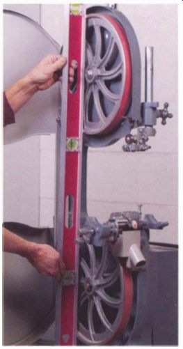
---------- A straightedge tests whether the upper and lower wheels run
in the same plane, which is crucial for reducing wear on the saw's tires and
reducing stress on the blade.
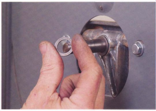
-------- On most saws, bringing wheels into the same plane simply means
adding or subtracting washers on the axle between the wheel hub and the frame.
Alignment on Large Machines ------- I wouldn't worry about checking wheel alignment on large machines where you can't get in with a straightedge unless the blade is obviously skewed on the wheels and can't be made to track properly. On smaller Delta-style machines, it is worth checking the wheel alignment; wheels are frequently out of line and the correction is easy to make.
WHEEL ALIGNMENT
When aligned correctly, the wheels are in the same plane (see the illustration at right). To check, place a straightedge across the rims of both wheels at the same time. On Delta-style saws, this can be easily accomplished with the table in place, but on many other saws the table must be removed, a daunting job on a big machine with a heavy, cast- iron table.
A second problem with some machines is that the wheels are set back in the frame and the straightedge can't reach the rims unless it's notched to clear the wheel housing. A shop made plywood straightedge is helpful.
Lay the straightedge across the rims of both wheels, adjusting the tilt of the upper wheel to bring it parallel to the straightedge (see the photo at left on p. 156). Ideally, both edges of both rims will touch the straightedge.
If they do not all touch, one of the wheels will need to be adjusted, in or out, by adding or subtracting shim washers on its axle as shown in the photo above right). On most Delta-style saws, the upper wheel is adjusted, whereas on Jet and some Craftsman saws it is the lower. One aftermarket supplier offers a kit of graduated shim washers for Delta bandsaws and its clones to make adjustments a simple task.
Once the wheels are aligned, install a medium-width blade (a 3/8-in. blade is fine) on the saw and lightly tension it. With the power still disconnected, turn the upper wheel by hand as you fully tension the blade and adjust the tracking to center the blade on the upper wheel, making sure that the guides are fully backed off and not touching the blade.
With the blade centered on the upper wheel, check that it's centered on the lower wheel also. If it isn't, you may want to readjust the wheel alignment washers to compensate for the flex of the saw's frame and wheels under load.
LINING UP THE GUIDES AND POST
If a bandsaw is to cut properly, the blade guides must be set correctly, and the setting should stay the same as the guide assembly is moved up or down to accommodate stock of different thicknesses. A misaligned guide post throws the settings off as the assembly is moved, so an important part of a tune-up is to make sure the post is straight.
On saws where blade guides can be adjusted, shift the entire upper and lower blade guide assemblies to center them on the blade's path (see the photo at left below). Next, lower the guidepost until it is close to the table, then move one of the side bearings or blocks in until it almost touches the blade (all the other blocks and bearings should still be pulled back). Now raise the post to its highest setting and check that the block still just clears the blade, which would mean the post is properly aligned and moving parallel to the blade. If the gap either disappears or grows larger, it means the post is out of line. Unless it is realigned, you will be forced to readjust the guides each time you change the height of the upper blade guide-an unnecessary pain in the neck.
On some saws, the guidepost mounting bracket can simply be loosened and shifted to get the post properly aligned. On Delta-style saws, however, the only way you can adjust the post alignment is by tilting the entire upper frame casting. This is done by inserting a shim between the upper frame and the base casting, which isn't that hard to do. Cut the shim about 3/8 in. wide and a bit longer than needed, then install the shim by loosening the bolt holding the frame together and slipping the shim into the joint (see the photo at right below). Cut off the excess shim after retightening the bolt. You'll need to determine the proper shim thickness by trial and error. The last time I did this, a piece of aluminum flashing 0.010 in. thick worked perfectly. If you changed the post alignment, check that the upper guide assembly is still centered on the blade path; you may need to readjust it.
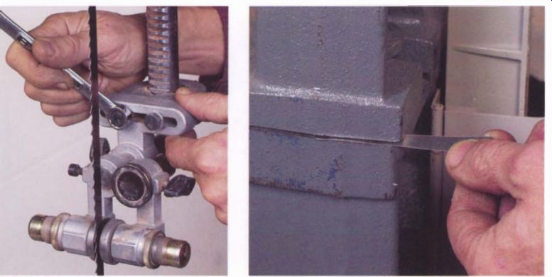
---------- To support the blade properly, you must adjust the entire guide
assembly from side to side so it is centered on the blade's track.
----------- Inserting a shim in the joint between upper and lower frame pieces may be the only way to keep the guidepost straight as it is adjusted up or down. The procedure is easy.
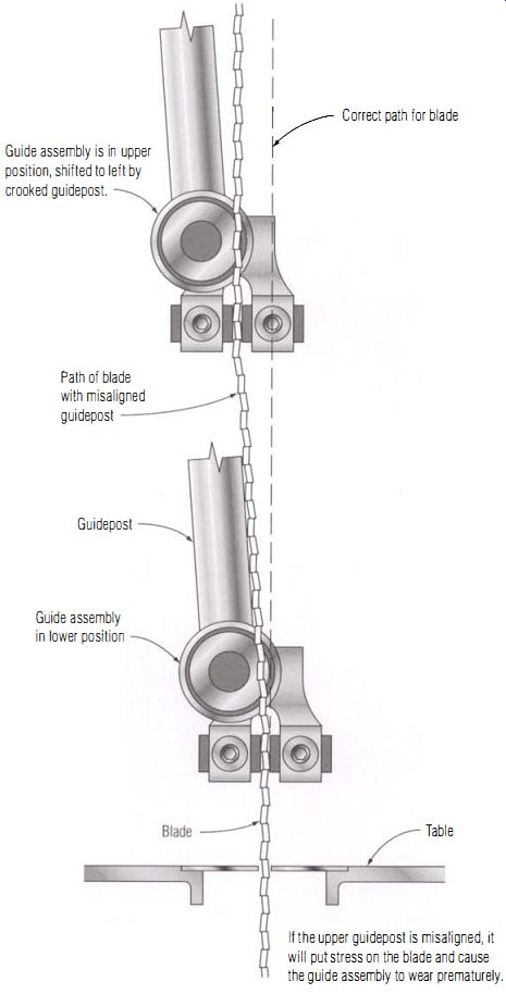
-------- A Crooked Guide Arm ---------- If the upper guidepost is misaligned,
it will put stress on the blade and cause the guide assembly to wear prematurely.
SQUARING UP THE TABLE
The only remaining setup procedure is to square the table to the blade.
Begin by backing off the blade guides and adjusting the blade to full tension and proper tracking in the center of the wheels. Place a square on the side of the blade and rotate the table in the trunnions until the blade is square to the table, then set the 90-degree stop if your table has one. Once the table is square, adjust the pointer or move the tilt scale to read zero (see the photo below). Later, when you make test cuts, you can fine-tune this setting.
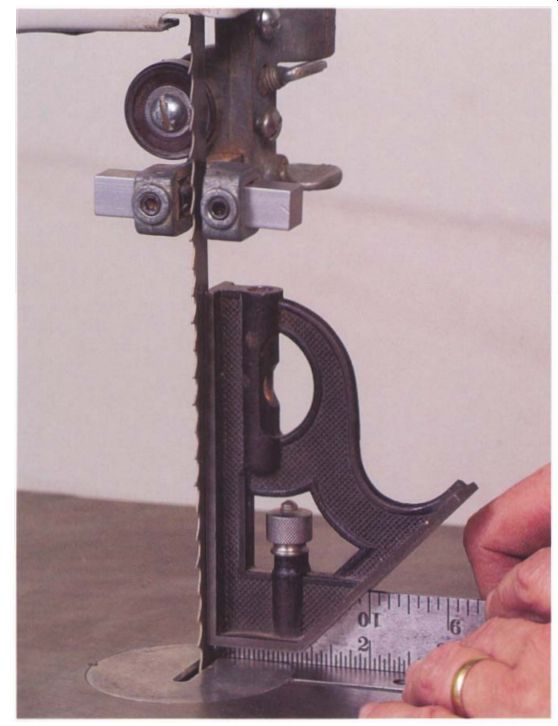
---------- One of the last steps in setting up a bandsaw is to make sure
the table is actually square to the blade when the pointer reads 0 degrees
on the tilt scale.
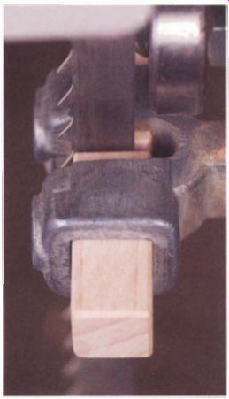
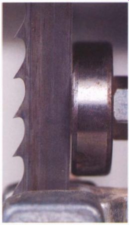
----------- On wider blades, the guide block or side bearing is positioned
to touch the blade at the base of the gullets.
The last alignment to check is whether the back of the blade is square to the table, although this is important only if you are going to be cutting joints such as tenons or dovetails on the saw. If the blade isn't square, the only fix on most saws will be to insert shims between the trunnion-support casting and the base of the saw.
That's it. Setting up a bandsaw is a long process. But now the saw should need only routine maintenance, which mostly amounts to cleaning and lubrication, although the guide blocks and bearings will occasionally need repair or replacement. The next section will explain how to adjust the guides to the blade you are using and line up the fence and miter gauge.
Tuning Up a Bandsaw
Once the bandsaw is properly set up, the adjustments that are needed for a tune-up will go quickly. Begin by unplugging the machine and installing a good blade for crosscutting the 1-in. stock of the test board. A 10-tpi or 12-tpi, 3/8-in. -wide blade is a good choice. Before installing the blade, pull back the guide blocks and bearings far enough so they won't touch the blade while you adjust the tension and tracking.
INSTALLING A BLADE
While turning the upper wheel by hand, alternately adjust the tension and tracking controls to get the blade to full tension and centered on the upper wheel face (if you've just finished setting up the saw, you will already have the blade in the machine). On small machines, where the tension gauges typically read low, tension the blade to the next highest setting. I then usually turn on the machine and let it run for a minute to make sure the blade is settled in and tracking properly. Once the blade is set, it is time to position the guides.
ADJUSTING THE GUIDES
Always unplug the power before adjusting the guides because your fingers are just too close to the blade if the machine should accidentally start.
Begin by lowering the upper guide until it will clear the stock to be cut by 0.25 in. to 0.5 in. At this point, none of the blocks or bearings, above or below the table, should be touching the blade. From here on, you can fully adjust one guide assembly at a time or move back and forth between them for each step.
Next, move the entire guide assembly forward or back until the leading edge of the side blocks or side bearings will touch the blade just behind the deepest part of the gullet (see the photo at left). If needed, bring one block close to the blade to check the position. When the alignment is right, lock its set screw.
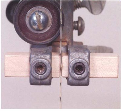
Bring the thrust bearing forward until it either just touches the back of the blade or there is a very small gap between it and the back of the blade as shown in the photo at right. When it's set right, lock its set screw.
Now bring one side block or side bearing in to just touch the blade.
Keep pushing the blade toward the block with a series of light touches.
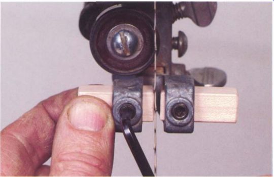
This will allow you to feel the gap closing, which is often easier and more accurate than setting the gap by eye. When the last bit of flex disappears, the block or bearing is in the correct position and you can tighten it down (see the photo below). The final step is to position the second side bearing. If the block is soft-made of wood, brass, or plastic-you can lightly pinch the blade against the opposing block and lock it in place (see the top left photo on p. 162). If the block is made of steel or ceramic or if it is a ball bearing, leave a slight gap. Pinching a piece of paper between the blade and the block or bearing before tightening the set screw will give you the right setting (see the top right photo on p. 162). Once both the upper and lower guides are set, turn the upper wheel by hand through several revolutions to make sure there are no kinks or a poorly ground weld on the blade that will bind as it passes through the guides. If moving the blade by hand goes well, restore power and turn on the machine for a final check.
--------- Set the first guide block (it doesn't matter which side you
start with) so it just touches the blade but does not push it to the side.
------------ Move the thrust bearing so it lightly touches, or nearly touches,
the back edge of the blade. During a cut, the bearing prevents the blade from
moving backward.
-------------- If blocks are made from a soft material, you can press the
second one lightly against the side of the blade and then lock it in place.

-------------Narrow blades may be fully enclosed by soft guide blocks
to increase support and reduce bowing or twisting. Hard blocks would ruin the
blade when used this way.

---------- Blocks made of ceramic or steel, as well as ball-bearing guides,
should be adjusted so there is a very slight clearance between block and blade.
A piece of paper sets the distance and is removed once the block's set screw
is tightened .lf blocks are made from a soft material, you can press the second
one lightly against the side of the blade and then lock it in place.
Test Boards -------- For the test board, use a wood that doesn't have a strong grain that can drag the blade out of line. Poplar, maple, cherry, or a fine-grained pine would all be good. Choose a straight-grained board 2 in. thick, 3 in. to 4 in. wide, and a couple of feet long. Joint and thickness-plane the board to get it straight and square.
With the machine running, you may find that the ball-bearing guides are spinning. You might want to back them off a bit more if you don't want them to turn when you aren't feeding stock, but this increases the chance that the blade will bow and cut less accurately. If you back off the thrust bearing, be careful that the blade can't push back so far that its teeth are damaged by striking either hard blocks or the rims of the ball bearings.
On narrower blades, the procedure for setting the guides is the same until the blade width drops to less than 0.25 in. On these narrower blades, you will get better blade support if you use soft-sided blocks that won't damage the blade's teeth and you position them to bear on the entire side of the blade including the gullets. On very narrow blades, you can completely enclose the blade. Bring the second block in as you move the blade by hand with the upper wheel so that the saw's teeth will cut their own clearance groove into the block faces (see the photo at left). The procedure for setting upper and lower guides is the same.
ADJUSTING THE MITER GAUGE
Once the guides are adjusted, you can set the miter gauge. Using a trued-up piece of lx4, take a test cut with the gauge and check the cut face, both horizontally and vertically, with an accurate square. Adjust the stop on the miter gauge and the table trunnions to get 90-degree corners in both directions.
ADJUSTING THE RIP FENCE
The final adjustment is to line up the rip fence, which is done by making test cuts with the blade you will be using for ripping (you will have to readjust the rip fence each time you switch to a different blade). On Delta-style saws, use a 1/2-in.-wide blade, the widest that can be properly tensioned, and tension it to the 1/4-in. blade setting. Choose a 4-tpi to 6-tpi blade for sawing a 2-in.-thick test board.
Start by setting up the saw with the blade fully tensioned and the guides properly adjusted. Draw a line down the length of the board, 0.5 in. from the edge, then rip the board freehand along this line with the wide side of the board on the side of the blade where you would normally mount the rip fence. As you follow the line, adjust the feed angle to find the orientation where the blade will naturally cut straight without drifting from side to side (see the photo above left). Once you have sawn a few inches without having to make corrections to stay on the line, hold the board in place and turn off the saw. Without allowing the board to shift, draw a pencil line on the saw's table along the back edge of the board (see the photo above right). Remove the board, then mount the rip fence on the table close to the pencil line. Loosen the adjustment bolts for the fence bar and shift it to match the orientation of the pencil line, then angle it a few degrees more toward the blade before tightening the adjustment bolts (see the photo at right). The added toe-in creates a slight side pressure on the blade that dampens vibration and produces a smoother cut. As a final check, make a full-length rip on the test board. If the cut is straight and smooth, you are done with the tune-up. If the cut wanders or is very rough, check the blade tension and guide settings. If they're good, try changing the rip-fence alignment slightly.
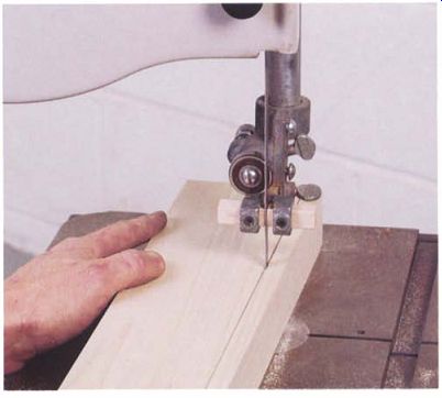
------ To adjust the rip fence, start by ripping a milled test board freehand.
When the saw is cutting to the line without course corrections, stop the saw.
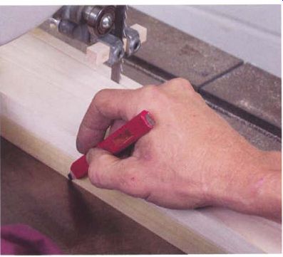
--------------Once you've found the lead angle, mark it on the table with a
pencil.
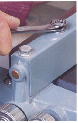
------------ The rip fence is lined up with the lead angle drawn on the
table and then toed in toward the blade a few more degrees. The slight cant
reduces blade vibration and makes for a smoother cut.
Prev. | Next | Article Index | Home