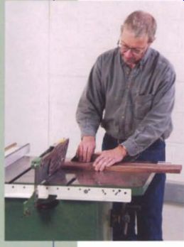
A table saw is at the heart of most woodworking shops. It is a simple, sturdy machine used mainly for ripping and crosscutting, but it also can be used to create a variety of woodworking joints, moldings, and raised panels.
In cabinetmaking, a fraction of a degree or a few hundredths of an inch can make the difference between first-rate workmanship and something that seems sloppy or poorly made. A well-tuned table saw allows you to work accurately to very close tolerances and to do it confidently. Even if the saw is used only for rough work, it should be reasonably well tuned. A badly adjusted saw is frustrating and, worse, dangerous to use.
Tuning up a table saw is a straightforward job that usually can be completed in an afternoon. Your reward will be a saw that works smoothly and cuts stock accurately, and your saw-blades will last longer because they won't overheat.
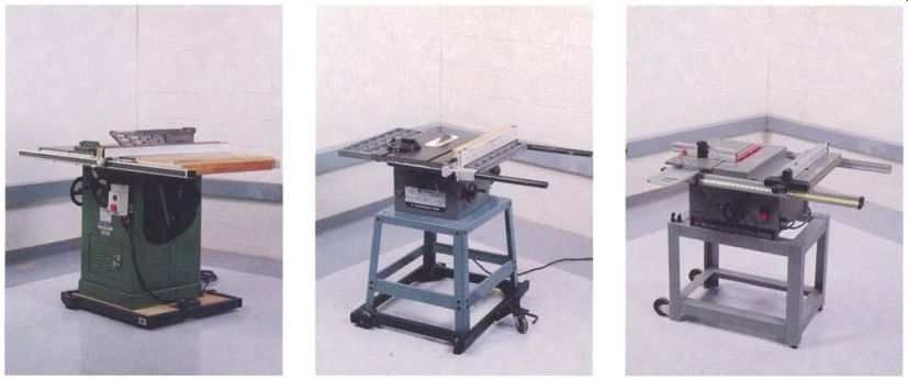
---------- A cabinet saw has an enclosed base and a powerful motor. Its
heavy castings contribute to smooth, vibration-free cuts.
A contractor's saw is designed so it can be moved to a job site, but it is lighter and less powerful than a cabinet saw and may show more vibration.
Benchtop table saws offer portable yet sophisticated designs that make them useful for cabinetmaking.
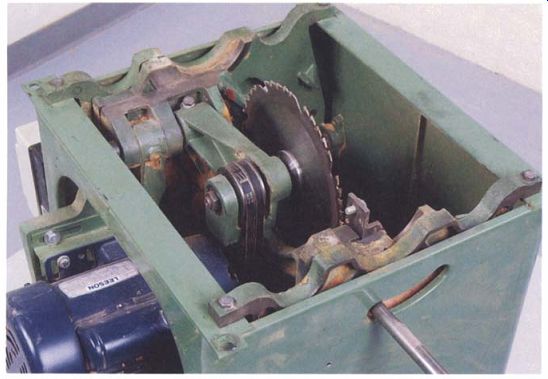
------------ Cabinet-saw components, including its massive motor and trunnion
assembly, are attached to the base, not the top. The design simplifies some
tune-up adjustments while offering better access to working parts for major
repairs.
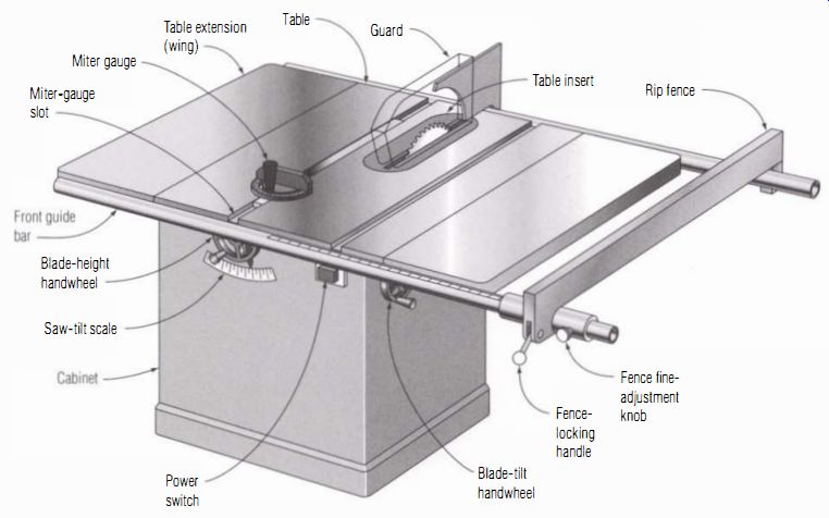
------------ The Table Saw ----- A cabinet saw is heavy and powerful, and
the enclosed base aids dust collection. The rip fence on this saw locks on
both the front and rear rail; some fences lock only at the front.
Table-Saw Types
Table saws fall into three general categories: cabinet saws, contractor's saws, and bench top machines. Except for the location of the motor and general heft of the machine, cabinet saws and contractor's saws are very similar in design. Modern benchtop saws, which use compact motors and aluminum castings, are distinctly different.
Cabinet saws are the heaviest and most powerful of the group. They have an enclosed steel base, which gives them their name, a cast-iron table, and motors of 2 hp to 5 hp. Smooth running and powerful, cabinet saws have been around since the 1930s and are essential equipment in most professional shops. Typically supplied with cast-iron extensions (also called wings), they are often supplemented with laminate-covered extension tables, which make the saws more convenient and safer to use. Because the running gear is mounted on a single, large casting, cabinet saws tend to be stable and therefore very accurate. The extra stability also means saw parts are not as likely to rattle out of alignment. From a maintenance point of view, cabinet saws have an essential advantage: The motor and arbor assembly is attached to the base cabinet rather than to the top (see the bottom photo on p. 53). This makes it easy to align the miter gauge slot with the blade. An enclosed base also improves dust collection.
Contractor's saws were designed so carpenters could take them to the job site. Weight-saving design compromises, however, reduce the saw's accuracy and increase vibration. Cast- iron components are lighter than those on cabinet saws, and they are not made from a single casting.
Contractor's saws come with either cast-iron or stamped-steel table extensions, although extensions on some older saws were open cast- iron grids.
Motors on contractor's saws are suspended from a bracket at the back of the machine, allowing it to be removed for transportation (see the photo at left on the facing page).
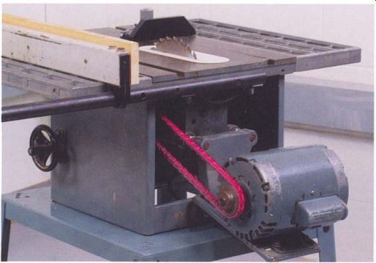
------ The motor on a contractor's saw pivots from the back so its weight
tensions the single drive belt. Although the design makes it easy to remove
the motor, it also can create additional vibration, especially when the belt
is worn.

------------ Dust collection is often excellent in newer benchtop table
saws, thanks to a die-cast aluminum housing that fully encloses the blade.
Vibration is the most obvious liability with this design, and it shows up in rougher cuts. Contractor's saws also can be hard to tune because the arbor assembly flexes under the weight and torque of the motor. Both problems can be addressed, but contractor's saws are not the best choice for precision work, and their open design makes dust collection more difficult.
Modem bench top saws, which have plastic bases, aluminum die-cast tops, and high-speed universal motors, have been around for almost 30 years, but they have only recently grown in size and sophistication to become a useful tool for cabinetmakers. The smaller motors in these machines achieve their high-horsepower output by turning at better than 10,000 rpm. The gears or cogged belt inside the housing are designed to bring this down to a more sedate 3,000 rpm to 4,000 rpm at the arbor shaft.
Benchtop saws are not as rugged as cast-iron saws, but the best of them now have full-sized miter-gauge slots and reliable rip fences. The design, finish, and operation of these machines is usually excellent.
Benchtop saws tend to have adequate power, but the motors make an unpleasant, high-pitch whine. Dust control, however, is very effective because the blades are enclosed in a shroud that directs sawdust into a vacuum port (see the photo at right).
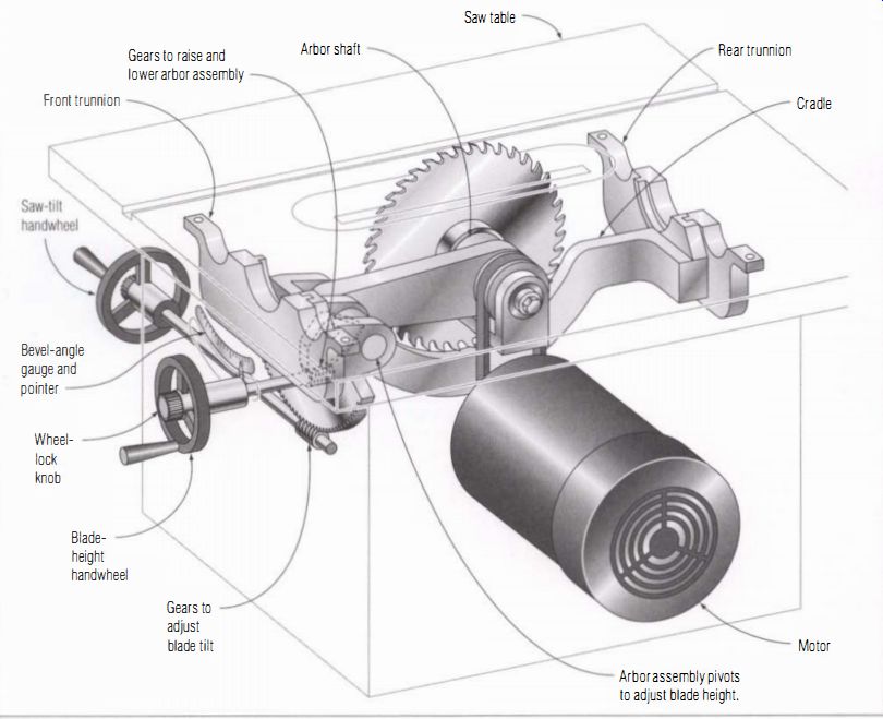
-------- Inside a Table Saw -------- Trunnions on cabinet saws and contractor's
saws allow the blade to pivot for making bevel cuts.
Contractor's saws have a single belt connecting the rear-mounted motor and arbor pulley; cabinet saws typically have multiple belts with the motor inside the cabinet.
How the Saws Work
For all their versatility, table saws have relatively few controls. One handwheel raises or lowers the blade to adjust the depth of cut, and a second hand wheel tilts the blade to one side to make angled cuts. The on/off switch is either mechanical or magnetic. The blade itself is mounted on an arbor and held tightly against a flange with a heavy nut and washer. On contractor's and cabinet saws, power is transmitted to the arbor via one or more V-belts and pulleys. On higher-horsepower cabinet saws, there may be two or three parallel belts to handle the increased power. Benchtop machines are direct drive, meaning that the end of the motor shaft 1S the arbor (a few have an intermediate gear). To tilt the sawblade, the arbor shaft, its housing, and the motor assembly must move as a unit. On cabinet saws, the arbor and motor assembly, which can easily weigh 100 lb. or more, hangs from trunnions at the front and back of the machine. At each trunnion, curved tongue-and-groove parts support the weight of the assembly while allowing it to tilt (see the illustration on the facing page). To adjust blade tilt in cabinet saws, contractor's saws, and some benchtop machines, a handwheel-operated worm gear drives a second gear mounted on the arbor assembly. The arbor on a cabinet saw is mounted on a swinging arm. To adjust blade height, a handwheel turns a set of gears and pivots the arm up or down.
Benchtop saws, which don't have the mass of cast iron to support, use simple hinge pins to support the motor and arbor unit under the table (see the illustration on p. 58). To keep the sawblade centered in the slot at all angles, the hinges on these saws must be kept small and tucked up very tightly under the tabletop. Benchtop saws also use a very different system to control the blade height. The entire motor and transmission unit slides in tracks that are molded into the main casting. The unit is controlled by a threaded rod and nut that are mounted along one side of the slide assembly. The rod is rotated by a hand wheel on the front of the saw.
Almost all new table saws, regardless of type, use 10-in. blades. Older machines sometimes have 8-in. or 9-in. blades. The craftsmanship on some of these earlier machines, by the way, is superb, and they can represent a real bargain if you find one in good condition and you can live with the reduced depth of cut.
Tuning Up the Table Saw
A complete tune-up involves a number of steps. It makes sense to clean and lubricate the saw's working parts first, before checking and adjusting the saw's components and settings. I take the work in the following order:
• Pulleys, belts, and bearings
• Table extensions, table insert, and splitter
• Alignment of blade and miter-gauge slot
• Rip fence
• Blade-tilt settings
• Miter-gauge stops
Some of these steps-such as making sure the miter-gauge slot and the rip fence are parallel to the sawblade-take some tinkering, yet they are essential. Also essential is checking blade-tilt settings and miter-gauge stops for square and 45 degrees. If you get these elements right, your saw will consistently cut stock square and straight.
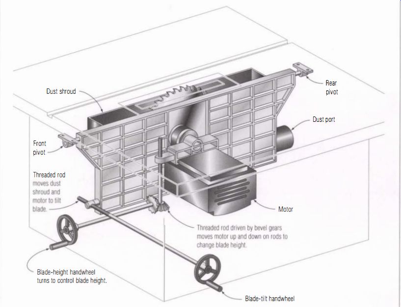
--------------- Modern Benchtop Saws ---------- Benchtop table saws use
a different design. The shroud enveloping the blade makes dust collection
highly efficient.
It may not be glamorous to start by cleaning and lubricating the saw's moving parts and inspecting belts, pulleys, and bearings, but a clean, well-oiled machine is easier to work on, and it will hold its settings longer and more accurately. Just as important is to double-check the settings that were made when the saw was put together: the extension wings, the table insert, and the splitter.
Except for aligning the miter-gauge slot with the blade, the tune-up and basic setup procedures can be done separately anytime you think something has slipped out of line. Adjusting a saw's miter-gauge slot alignment, however, will throw off the rip fence and miter-gauge settings, so always begin a full tune-up by checking and aligning this key setting before moving on to the fence and miter-gauge adjustments.
There are hundreds of models of table saws, some with unique design features. The maintenance procedures I describe here are for the most common saws, but you may have to do some sleuthing on your own machine to find adjustment screws and lock bolts. Before beginning, you might find it helpful to spend some time with a flashlight under your machine to identify its components and understand how they function.
Choosing the Right Blade
In addition to a good tune-up, choosing the correct blade is a key to getting the best performance from your table saw. You can do a lot of agonizing over which sawblade to purchase: a rip, a crosscut, or a combination.
Are 60 teeth better than 20? Should the tooth pattern be an alternate-top bevel or triple chip? And is any blade really worth $100? (For help in choosing a blade, see the sidebar on p. 60). Actually, it's all pretty simple, including the question of price. With saw blades, you really do get what you pay for.
Almost all of the better-quality blades made today have carbide teeth (see the sidebar on p. 61). Although all-steel blades have been nudged aside, they did have some advantages. They can produce a superb cut because the teeth can be sharpened in profiles that are impossible with brittle carbide. Steel teeth also can be sharpened easily right in the shop or at low cost by a local sharpening shop. But the increased use of highly abrasive man-made materials, such as MDF, as well as the falling cost of carbide tooling have made carbide-tipped blades the standard.
Initially there were only two types of sawblade for wood-rip blades for cutting with the grain and crosscut blades for going across the grain.
You would have to change from a rip blade to a crosscut blade depending on which type of cut you were making. Blade manufacturers, seeing a big market, developed the combination blade, which can both rip and crosscut.
Ragged or burned cuts, kickback, and difficulty feeding the board can be caused by a warped, dirty, or dull blade or by using the wrong blade for the job. A quick test is to switch to a different blade: If the problem clears up completely, it's obvious what the problem was. Little or no improvement suggests alignment problems.
----------------- ------------
Selecting the Right Blade for Your Saw
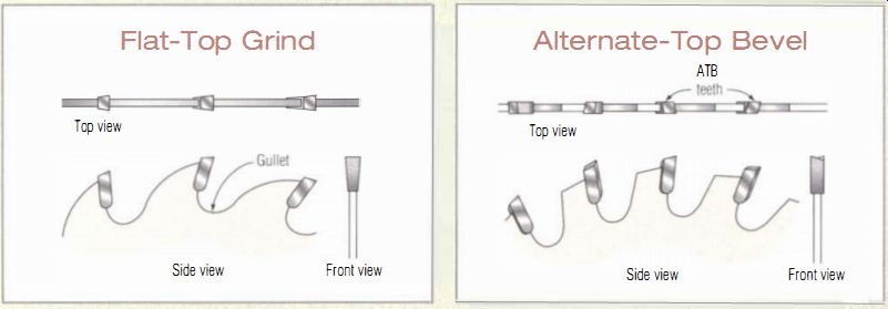
----------- Flat-Top Grind
----------- Alternate-Top Bevel
You WILL GET THE BEST RESULTS FROM YOUR TABLE SAW by choosing the correct blade for the job you're doing. The four types are rip blades, crosscut blades, combination blades, and triple-chip blades.
Rip blades, which are designed to cut with the grain, have a flat-top tooth profile, called a flat-top grind (FTG). Each tooth takes a long, plane-like shaving, while the blade's deep gullets clear debris quickly.
There are typically no more than 24 teeth on a 10-in. blade. Rip blades are especially good on stock thicker than 1X in. and on tough wood such as oak and tropical hardwoods. Rip blades are a necessity for cutting green wood and some softwoods because the stringy shavings clog up the smaller gullets of combination blades.
A crosscut blade has a different tooth shape. The profile comes to a sharp point that cleanly slices the wood fiber. Teeth are beveled across their width.
Since the blade needs to cut along both edges, the bevels reverse their slope from tooth to tooth, hence the name alternate-top bevel (ATB) . Sixty teeth on a 10-in. blade is common. Crosscut blades do well at cutting MDF and plywood but may cause some chipping of veneers and melamine facings.
A combination blade is exactly that, a mix of alternate-top bevel teeth and flat-topped teeth called rakers. The typical ratio is four ATB teeth followed by a flat-topped raker with a deeper gullet. The tooth count falls in the mid range, 30 to 40 teeth in a 10-in. blade. Some combination blades have ATB teeth only, without the rakers. They rip somewhat more slowly than the blades with rakers and probably crosscut a bit better. A combination blade works well with both solid wood and man-made materials, but it may bog down when used for heavy ripping and may cause some chip-out on veneers.
Triple-chip blades are designed for very hard materials that chip easily, such as melamine. Teeth beveled at each corner alternate with rakers, which may be either flat topped or in an alternate-top bevel design.
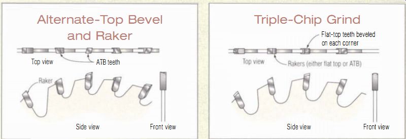
---------- Alternate-Top Bevel and Raker
---------- Triple-Chip Grind
----------------------
------- ---------
On the Edge
CARBIDE IS A SIMPLE CHEMICAL compound consisting of a metal, typically tungsten, and carbon. Pure carbide comes in the form of microscopic granules. Grains of carbide are cemented together with a binder, such as cobalt, to form saw teeth.
A carbide cutting edge is extremely hard, so it doesn't wear away very quickly. Heat and chemicals in wood resin and adhesives, however, attack the binder. Once the binder fails, the carbide grains break free and the cutting edge loses its shape. Carbide cutters also fail by fracturing. Sawing through especially hard knots, common in some tropical woods, or striking embedded gravel can shatter a tooth. Most blades, in fact, have a few chipped teeth after they've been used for a while.
The amount and type of binder and the size of the carbide grains affect both chemical resistance and toughness. Unfortunately the more chemical-resistant combinations tend to be more brittle. The best, most highly engineered carbides are the most expensive. This is part of what you pay for in a top-of-the-line blade.
-----------------
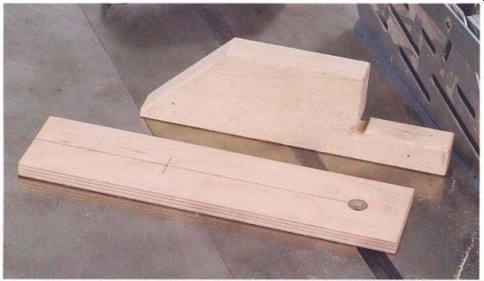
---------- A mounting block for a dial indicator (top) and a plate made
from plywood are essential but easy-to-make tools for aligning the miter-gauge
slot and the rip fence to the blade.
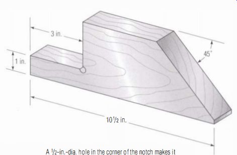
------------- Dial Indicator Mounting Block --- A 1/2-in.-dia. hole in
the corner of the notch makes it easy to saw into the corner neatly. Bevel
the hole's edges with a countersink before sawing out the corner.
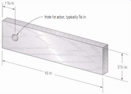
--------------- Arbor Plate --- Baltic birch plywood is a good choice for
the arbor plate because it is strong and stable.
Assembling the Right Tools
For checking both the alignment of the miter-gauge slot and the rip fence and for checking arbor runout, you will need a dial indicator with a shop-made mounting block and a rectangular piece of Baltic birch plywood. You may need some extension tips for your dial indicator, but they don't have to be expensive. You also will need an accurate square, either a machinist's or combination style, and an assortment of wrenches, screwdrivers, and hex wrenches.
The mounting block shown in the photo above is a piece of straight-grained pine. It should be 1 in. to 1 1/2 in. thick and cut to the shape shown in the top illustration above, but it's not critical that you use these exact dimensions. Beveling all the edges will keep them from getting nicked.
The dial indicator may be mounted in several positions on the block, depending on the test you are performing (see the photos on the facing page). It's better not to attach the indicator until you are setting up each test.

------------- When clamped to the block this way, the dial indicator is
used to check the alignment of the miter-gauge slot to the blade.
------------ Attached to the sloped end of the block, the indicator can be used to check for any wobble on the arbor flange.
Mounted in place of the blade, the plywood plate (see the top illustration on the facing page) will be used to check the alignment of the arbor with the miter slot and the rip fence. Baltic birch is cabinet-grade material with smooth, hardwood veneer on both faces. I use a piece 1/2 in. thick.
This kind of plywood has more laminations than ordinary plywood, making it strong and stable. The hole should be sized for your arbor, which is 1/2s in. on most modern saws. Lightly sand both faces of the plate, but don't apply a finish because the wood needs to show a pencil mark. Draw a centerline down the better face of the plate.
You might wonder whether a plywood plate is accurate enough to be used as a reference for checking the accuracy of machine parts. After all, a dial indicator can detect very small amounts of wobble, and several companies sell $50 precision steel disks for the same purpose. There would be a problem if the indicator were used to measure more than one place on the plate; the slight variations in thickness would make accurate measurement impossible. My method skirts this problem because all measurements are made against the same spot.
Moreover, the rectangular shape of the arbor plate extends well beyond the blade opening so front and rear measurements are taken at locations much farther apart than they would with a steel disk. As a result, the effects of any misalignment are larger and easier to measure. I'll explain how to use the plate in "Aligning the Blade and Miter-Gauge Slot" on p. 73.
Cleaning and Lubricating
Like all machinery, a table saw benefits from regular cleaning and lubrication. In a busy commercial shop, this could be as often as every few weeks. In a home shop, once or twice a year is adequate, perhaps in the fall after you've taken a summer break from woodworking or just before starting a big project. Start by donning a dust mask and removing the bulk of the sawdust inside the machine with a shop vacuum. Use a hand-held brush to remove any dust in the corners you can't reach with the vacuum nozzle.
Once you've gotten as much debris as you can with the vacuum, use an air compressor to clear away the last of the dust from the hidden recesses of the machine. If you don't have one, switch the vacuum hose to the exhaust port and use the nozzle as a blower.
Lubricating woodworking machinery in general is problematic and table saws are the worst of the lot. On the trunnions and adjusting gears, lubricants such as lithium or bearing grease instantly load up with sawdust.
The grease is pushed aside in useless, hard-to-remove clumps. Oil, of course, is an even worse dust magnet. I confess that I've resorted to a quick shot of penetrating oil to relieve binding or squeaking, but the effect doesn't last long.
The best lubricant I have come up with for exposed bearing surfaces on a saw is a white stick product in a push-up tube that I found at a local hardware store. It eliminates friction, but it doesn't attract dust as readily as grease. It looks and feels like slightly soft bar soap.
Before you apply new lubricant, try to remove most of the old, especially the dense dust and grease mixture that often encrusts the works of older machines. Once you've cleaned off the worst of the old grease, apply the new sparingly. It doesn't take much. The working layer of lubricant is only a few molecules thick, so any surplus will just attract dust and dirt.
Use the stick lube on the worm and gear and trunnions as you run the height and tilt mechanisms from stop to stop. Apply a drop of light machine oil to the control shafts where they pass through the castings and support bushings. Any moving part that is impossible to reach directly should get a shot of a spray lube through one of those easily lost little tubes that mount on the spray nozzle.
---------------
The Future Is Plastics
Bushings, gears, and mating surfaces in many of the new benchtop machines are made from plastic.
These parts don't need lubrication and can actually be harmed by the solvents in conventional greases and oils. On these surfaces, use silicone-based greases or sprays sparingly if at all.
-----------------
Know Your Saw
Even with experience it can be hard to tell what is normal and what is a sign of impending failure for the drive line of a power tool.
When a tool is new or at least new to you, give it a thorough inspection and note how the arbor feels and the sounds when you turn it. Remembering how the saw sounds when it's running properly can make it much easier to determine when there's been a change for the worse.
--------------------
Checking the Saw's Drive Line
It is unusual to have problems with the bearings in the motor or the arbor shaft. But problems with belts and pulleys are common, especially on contractor's saws. Depending on how the saw is constructed, replacing a bad belt or even tightening a loose pulley can require a considerable amount of work. In some cases, the saw must be disassembled. If repairs are needed on a cabinet saw, it is often easier in the long run to remove the table to gain complete access to the arbor and motor assembly. Contractor's and benchtop saws can be flipped over for servicing.
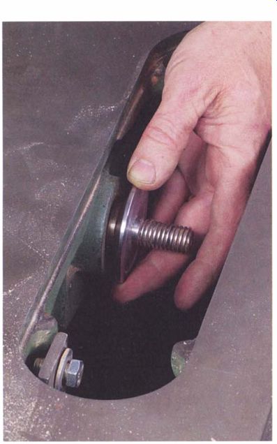
--------------Bearings in good condition will allow the arbor to be rotated
smoothly and silently. When the arbor catches or when a clicking noise is
audible, faulty bearings are typically to blame.
To avoid injury when working on a table saw (or any other machine, for that matter), make sure the tool is unplugged whenever you will be near the blade or other moving parts. Before unplugging the saw, however, run it both with and without the sawblade and listen and feel for unusual noise and vibration. A cabinet saw should make only a low steady hum and almost no vibration; a contractor's saw will be noisier on average but there should be only minor vibration.
The motors of benchtop saws run at high speed and produce a high-pitched whine. Listen for intermittent buzzes and vibration that come and go or a steady, fast rattle. These are a sign that bearings may be worn out.
The drive on these saws is an enclosed cogged belt or gears that rarely have problems, but a cogged belt or gear drive that is failing will produce sudden jumps and skips when sawing.
With the power disconnected and the blade removed, rotate the arbor by hand (see the photo above). The shaft should rotate smoothly with little noise. If you hear a grinding or clicking sound or if the shaft sticks abruptly, a ball bearing has probably reached the end of its life. To isolate the problem, disconnect or slack off the belts and rotate the motor and arbor separately. This is easy to do on a contractor's saw, but it's somewhat difficult on a cabinet saw.
A second test to run while rotating the arbor is to pull up sharply on the shaft as you rotate it. There should be no motion or clicking that would indicate worn bearings. As best you can on contractor's and cabinet saws, repeat this test on the pulleys of the motor and arbor shaft. Any motion here is probably due to a loose pulley. If you can reach the set screws on the pulleys with a wrench, it is worth checking that they are tight.
On a contractor's saw or cabinet saw, the arbor should have little or no side-to-side play, that is, play along its axis. If there is, it can probably be eliminated by adjusting the pulley or a large nut threaded on the shaft behind the pulley. A benchtop saw, if it is gear driven, may normally have some end play in the arbor shaft; under a load, this goes away.
A stiff or cracked belt will be felt as the arbor being alternately easier and then harder to turn, typically only once in several revolutions of the arbor as a bad spot on the belt reaches a pulley. A badly deteriorated belt will create severe vibration when the saw is running. Visually examine the sides of the belt as you move it. Look for cracks or patches of missing rubber and shiny spots that indicate the belt is hardening and slipping (see the photo above).
------------
A Better Belt
V-belts are so simple it hardly seems they could be improved.
But Power Twist Plus belts by Fenner Drives really are superior. Built like a bicycle chain with separate links, they are flexible and have a slight stretch resulting in a smoother transfer of motion.
------------
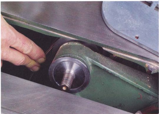
------------ The drive belt should be smooth and flexible with no signs
of cracking.
On a cabinet saw, press on the back of the belt midway between the pulleys; it should flex only slightly. If there's more slack, adjust the belt tension by adjusting the motor mount. On a contractor's saw, the belt is tensioned by the weight and position of the motor. Shifting the motor mounts to better align the pulleys and increase the belt tension often makes these saws run more smoothly.
Contractor's saws often suffer from a combination of poor-quality or worn pulleys and stiff belts. The end result is that the motor, which is cantilevered off the back of the saw, bounces and vibrates. This affects the quality of the cut and quickly throws the saw's arbor out of alignment.
Inline Industries markets a kit with two machined steel pulleys and a Power Flex Plus belt that can improve performance considerably.
Checking the Saw's Original Settings
When a saw is brand new, its various components must be assembled into a working tool. This process includes attaching the table extensions, adjusting the table insert, and making sure the splitter is aligned correctly.
Over time, these parts can drift out of alignment, so a full tune-up should include a look at all these parts and, if necessary, some readjustments. The insert and splitter are easy to adjust, but getting the wings to line up flat with the saw's main table may require some shimming.
----------------
On the Level
Before adjusting the wings, take a look at how the saw sits on the shop floor. The saw's base or stand should be equally supported at all four corners. If the saw is supported unevenly, stress will distort the machine all the way up to the table's surface. Use shims or add screw adjusters to the bottom of the legs to even up the load.
---------------
LEVELING A TABLE SAW'S WINGS
Leveling a table saw's wings can be difficult because mating surfaces do not always line up perfectly. But taking it slowly and methodically and using a few shims make this a relatively painless procedure. The process I describe here of leveling the wings with shims is intended for cast- iron extensions.
Getting stamped-steel extensions-like those on some contractor's saws in the same plane as the table can be accomplished by bending the wings once they are bolted to the saw. Stamped wings are too flexible to stay in line, however. They also need to have braces added so they remain rigid under a load.
Attaching a cast- iron wing is an awkward job because the casting is too heavy to support with just one hand while you get the bolt started.
Adding a knee to the process makes it much easier. Crouch down next to the saw with one of your knees directly below the wing's center bolt hole in the side of the saw's table, then stand the wing vertically, on its end, on top of your knee. The center hole in the wing casting should line up with the hole in the table. Sometimes placing a block or two of scrap under your foot, to raise your knee, will make it easier to get the holes in line.
Now with one hand and your knee supporting the wing, you still have one hand free for the bolt.
To level the wing, you should attach it to the table with all three bolts. Front and rear bolts should be snug; the middle one should be loose.
Tap the table with a non-marring hammer until the front edge of the wing is flush with the front of the table (see the photo on p. 68), then tighten the front bolt to three-quarters tight to hold it in place.
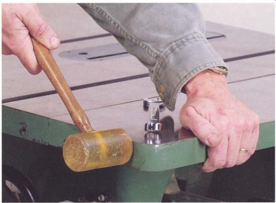
--------- With the attachment bolts snug but not tight, line up the front
edge of the wing and the top with a few light taps using a non marring hammer.
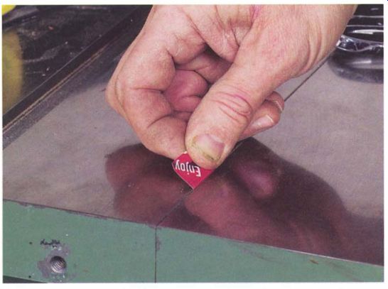
------------- Shims cut from an aluminum soda can are ideal for bringing
table-saw wings into the same plane as the main top.
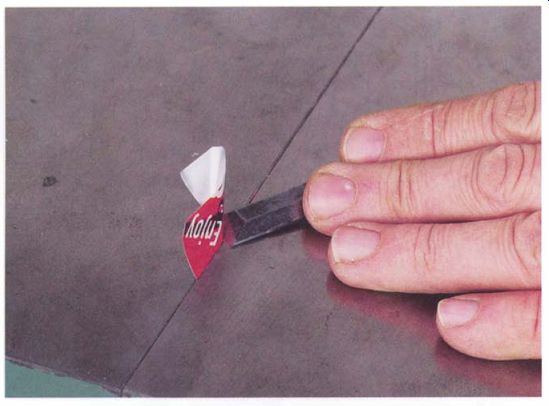
-------------- Shims installed from the top should be cut flush with the
top using a sharp chisel. Shims installed from the bottom are out of the way
and may be left exposed.
Next, move the back of the table up or down until it is flush over the rear bolt, and tighten the bolt to hold the table in position. Go to the front of the table and readjust it, if needed, so it's flush, both over the bolt and along the front edge. Go back and forth between the front and rear, making these adjustments until the top surface of the wing is flush at both ends and the front edge is flush, then fully tighten all three bolts.
Place a short straightedge over each bolt and note whether the joint between the table and the wing is flat, crowned, or dished. Typically, there is a crown because the outside edge of the wing sags slightly. If the wing is not on the same plane as the table, it should be shimmed. The aluminum from a soda can makes good shim stock, which you can cut with scissors.
Cut the shims 7:1 in. wide and 1.5 in. long, and fold a 0.25·in. tab along the long edge of each shim.
Now loosen all three bolts slightly, but not enough to allow the wing to lose its alignment to the table. Fully loosen one bolt and insert the 0.25 in. tab of the shim between the table and wing. The shim should be centered on the bolt (see the top photo on the facing page). You may have to flex the table with hand pressure to get the shim to slip in place. Insert the shim from below if the wing sags or from above if the wing rises. Retighten the bolt three· quarters tight.
Insert the shims at the remaining two bolts, checking that the wing and table are still flush at the joint, then fully tighten the bolts. Check to see if the wing and table are now in the same plane. If they are not in line, increase or decrease the thickness of the shims. Once the surfaces are flush, trim any visible shims using a chisel (see the bottom photo above).
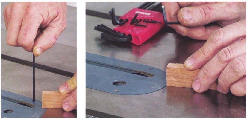
------------ Turn the set screw to raise or lower the insert until all
four corners are slightly below the level of the table.
----------- Sliding a small hardwood block over the edge of the insert is a good test: If the block catches, the insert is too high.
---------------
Tighten Up
Leveling screws in a table saw's throat plate may not have locknuts. A small plug of plastic may be inserted in the threads to keep the screws from backing out, or they may be held in place with a special adhesive. If an adjustment screw won't stay put because the insert or adhesive has failed, try using a spot of rubber cement on the threads.
------------
ADJUSTING THE TABLE INSERT
When the table insert isn't perfectly flush with or slightly below the top of the table, it can cause a board to bind during a cut. Adjusting an insert, however, is straightforward. It helps to have a small, hardwood block on hand for checking the fit. Cut one roughly 1 in. by 2 in. by 3 in. and put it on the table close to one of the adjusting screws that you'll find in (or under) the insert. Slide the leading edge of the block back and forth over the joint between the plate and the tabletop (see the photo at right above). If the insert is too high, you will feel the block catch on its edge.
Turn the screw to lower the plate's height until the insert is just below the edge of the opening. Repeat this procedure all the way around the plate at each adjustment screw (see the photo at left above). Once the plate is below the table height, place the block on the table near one of the screws at the infeed end of the plate. Slide the block back and forth while adjusting the screw to raise the plate until it just catches the block. Now back off the screw, just slightly, until it no longer catches; this is the proper height of the insert. After making the same adjustment at each screw location, the insert height should be correct.
ADJUSTING THE SPLITTER
Some boards are contorted by so much internal tension that they try to close around the blade during a cut. This dangerous condition, which can lead to kickback, is what a splitter is designed to prevent. The splitter, in some ways, is misnamed; it was never intended to force apart or separate the two halves of the stock. Its true purpose is to stop kickback by preventing the stock on the outfeed side of the table from making contact with the teeth at the back of the sawblade.
The splitter should be slightly thinner than the blade and directly in line with it. When ripping a board in two, neither piece should touch the splitter. Every saw maker has a slightly different method of mounting and adjusting the splitter, and you'll have to work out or look up the exact method of setting up the one on your machine. Unfortunately, many splitters are so poorly designed and flimsy that they can't be made to line up properly and hold a setting.
To check the splitter's alignment, cut two 1x2 boards so they are long enough to reach from the front of the blade to a point 6 in. beyond the splitter. Joint one face and one edge flat and square and mark the good faces. Then unplug the saw and mount a fine-tooth blade on the arbor, but don't replace the table insert.
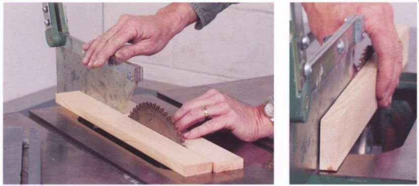
------------ A pair of jointed boards will quickly show whether the splitter
is correctly aligned with the blade. The splitter, slightly thinner than the
blade, should not touch either board.
------------ Adjust the splitter so it is parallel to the board's vertical edge. Some splitters will have to be gently bent into position.
Check that the blade is in the vertical position and close to full height. Place the boards on either side of the blade, making sure they bear on a tooth at both the front and the rear of the blade (see the photo at left below). The splitter should be in the middle of this gap, not touching either board. If not, you will have to adjust it.
With one board removed, check whether the side of the splitter is parallel to the edge of the board. If these two surfaces are not in line, the vertical alignment of the splitter will need adjusting (see the photo at right below). If the splitter's mounting bracket doesn't have an adjustment for the vertical alignment, you may need to bend or twist the splitter to correct its tilt and get it parallel to the plane of the blade (see the photo at left). Once the vertical alignment is right, adjust the nuts or shims that center the splitter to get it midway between the two boards.
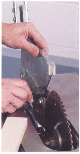
----------- Adjust the splitter so it is parallel to the board's vertical
edge. Some splitters will have to be gently bent into position.
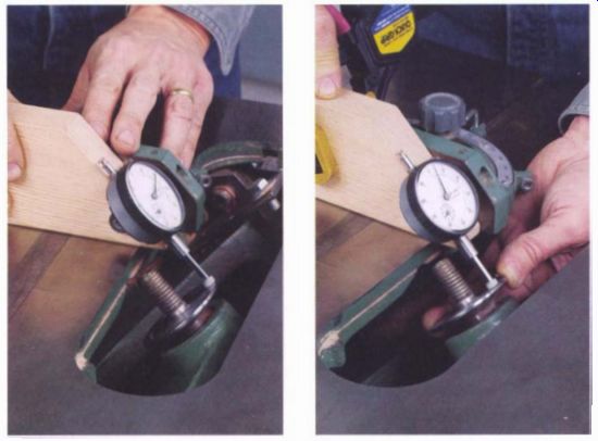
------------ Tilting the blade to 45 degrees makes it easier to check runout
on the arbor flange.
---------- After clamping the mounting block and dial indicator to the miter gauge, rotate the arbor slowly by hand. The difference between the widest swings of the hand is the runout of the arbor flange, which should be no more than 0.005 in.
Checking for Arbor-Flange Runout
The blade is mounted on the arbor and clamped against the flange by a nut and washer. If the face of the flange isn't flat, the blade will wobble as it rotates. A wobbling blade will produce a rough surface on the workpiece and make the saw work harder. It won't affect the squareness of the cut or cause burning of the cut surfaces; these problems are due to a misaligned rip fence or a badly warped blade. An out-of-true flange is rare and not something you'd have to check in an ordinary tune-up, but it is worth checking at least once, just to be sure. The amount that the flange is out of true is called runout.
Dust, resin, and burrs on the flange also can cause the blade to wobble, so before you test for runout, it's a good idea to clean the face of the flange using solvent on a rag, then lightly run a file over it to knock down any rough spots. Once that's done, you can measure runout. Here's how I do it: Unplug the saw and remove the blade, then tilt the saw to the 45-degree stop and raise the arbor to its highest position. Mount the dial indicator on the sloped face of the block. Place the miter gauge in the slot that the flange is facing, and position the block against the face of the miter gauge so that the tip of the gauge can bear against the face of the flange near its perimeter (see the photo at left on the facing page). On some saws it may be necessary to place an accessory tip on the indicator to reach the flange.
Slide the block toward the flange until the indicator has made a couple of revolutions and the hand stops at the 12 o'clock position. Clamp the block to the miter gauge, then zero the indicator while holding the block with one hand. Holding the block steady, rotate the arbor, preferably by pulling on the drive belt or the pulley to avoid bumping the stem of the indicator. The difference between the widest swings of the hand is the runout of the arbor (see the photo at right on the facing page). On a well-made saw that hasn't been abused, runout is typically no more than 0.003 in. at the rim of the flange. If you are getting higher readings, it's worth trying to correct it, especially if you aren't getting good sawn surfaces when using a high-quality blade. Correcting excessive runout by replacing the flange and possibly the arbor shaft is an option, but it requires a tear-down of the machine and a substantial outlay for parts. An alternative is to have the original arbor and flange machined true, but this still requires disassembling the saw.
Runout also can be corrected by filing down the high spot on the flange. Use a new file with the teeth ground off the narrow edges to pre- vent nicking the arbor shaft. As you file, check your progress with the dial indicator. It is tedious work but worth the effort.
-------------------
First Things First
Adjusting a saw's miter-gauge slot alignment will throw off the rip fence and miter-gauge settings. A full tune-up should start with aligning the miter-gauge slot with the blade, followed by checks of the fence and miter gauge.
Aligning the Blade and Miter-Gauge Slot
When the miter-gauge slot is not parallel to the blade-and you can't assume that it is-you'll get rough, burned, and out-of-square crosscuts. No amount of fiddling with the miter gauge seems to correct it. Because this problem is somewhat hard to check and rarely discussed in owner's manuals, many woodworkers are unaware of its importance or that it can be adjusted.
When the miter-gauge slot is not aligned with the blade, stock runs into the body of the blade as the cut progresses (see the illustration on p. 74). This causes three things to happen. First, the friction generates enough heat to burn the leading edge of the board and overheat the blade. Second, the stock is forced sideways, leading to a slight curve in the sawn edge. Finally, the board strikes the teeth at the back of the blade, risking kickback as the upward motion of the saw tries to lift the board off the table.
Adjusting the alignment on cabinet saws and most benchtop saws is fairly easy. On these machines, it is worth the trouble to adjust the alignment so there is only a few thousandths of an inch difference between the front and rear measurements. In fact, it's not that hard to get a near zero difference between the front and rear readings. Contractor's saws are harder to adjust and tend to go out of alignment easily, but you should try to get the difference between the front and rear readings within 0.005 in. if possible. On contractor's saws, always take your measurements with the motor and belt attached because the pull of the belt shifts the arbor's position significantly.
Depending on how carefully your saw was made, the miter-gauge slots may or may not be exactly parallel with each other. If they aren't, cuts made with the miter gauge in the slot you adjusted parallel to the blade will be good, while cuts made with the other slot may still have problems.
Other than replacing the top, there is no solution to this problem. Take your measurements from the slot you use most of the time.
----------------
Misaligned Miter Slot
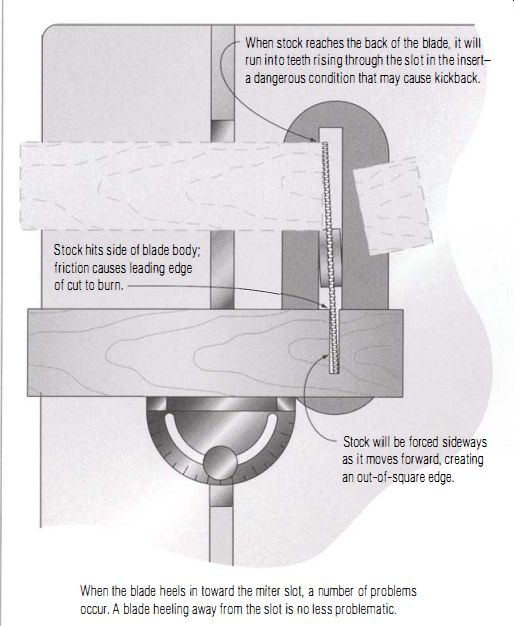
When stock reaches the back of the blade, it will run into teeth rising through the slot in the insert a dangerous condition that may cause kickback.
Stock hits side of blade body; friction causes leading edge of cut to burn.
Stock will be forced sideways as it moves forward, creating an out-of-square edge.
When the blade heels in toward the miter slot, a number of problems occur. A blade heeling away from the slot is no less problematic.
----------------
CHECKING THE SLOT ALIGNMENT
First, unplug the saw, remove the blade, and place the miter gauge in the slot you regularly use for making crosscuts. Raise the blade to just below its highest position, and install the arbor plate with its marked face toward the miter gauge.
Next, attach the dial indicator to the side of the notch in the block so that it projects from the end. Hold the block against the miter gauge, and position it so the tip of the indicator is on the centerline of the arbor plate. Now move the indicator toward the arbor plate so the hand of the indicator makes a couple of turns and comes to rest at the 12 o'clock position from your point of view. Clamp the bar to the miter gauge (see the photo at left below). Using a pencil, make a mark on the arbor plate where the indicator tip contacts the centerline. Use a square to lengthen the mark to make it easily visible (see the photo at right below). With one hand holding the miter-gauge assembly steady against the outside edge of the miter slot, use a fingertip to tap lightly a few times on the indicator stem and the face of the arbor plate to be sure they've settled into position, then zero the indicator (see the top photo on p. 76).
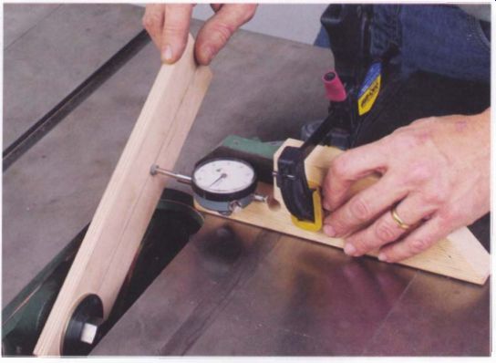
------------- Mounting a piece of Baltic birch plywood in place of the
blade allows a precise check of whether the miter-gauge slot is parallel to
the blade.
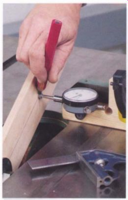
--------------- Marking the plywood arbor plate helps ensure a more accurate
test. The tip of the dial indicator should be placed on the same reference
point when checking the alignment from the front and back of the table.
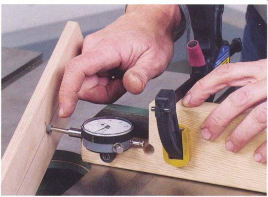
----------------- Before taking the reading, use your fingertips to tap
on the arbor plate and dial indicator to make sure the indicator has settled
into position, then zero the indicator.
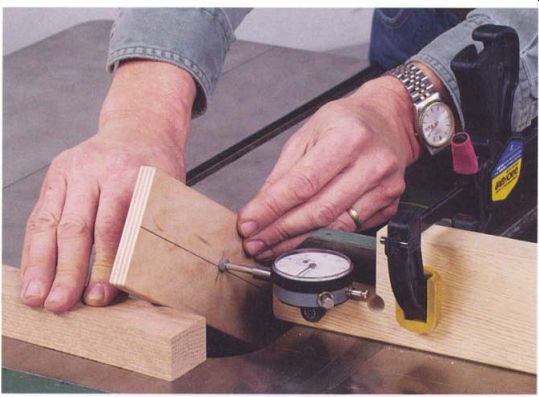
-------------- Take the reading at the back of the saw at the same center
mark on the arbor plate. A small block may be needed to prop up the plate
to bring the tip of the indicator on the mark.
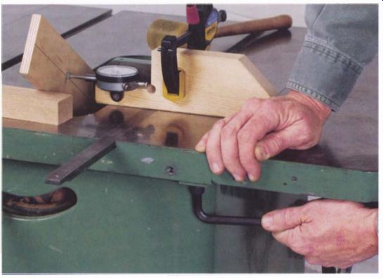
------------- To align the miter-gauge slot with the blade on a cabinet
saw, start by loosening the bolts that attach the top to the cabinet.
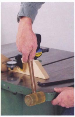
---------------- Once the table bolts are loosened, tap the top gently
to shift its position, then recheck the slot-to-blade alignment with the dial
indicator.
Rotate the arbor plate to the opposite end of the opening, and move the miter gauge forward until the indicator tip again touches the center line at the spot you marked earlier. You may need to prop the arbor plate on a small block (see the bottom photo on p. 76). If the dial indicator doesn't still read zero, the miter slot isn't parallel to the plane of the sawblade. To get an accurate reading, always apply light pressure to the miter gauge so that it stays against the outside edge of the slot.
Slightly flex the arbor plate with finger pressure to see which way brings you back toward zero. This will tell you which way the table needs to rotate to make the blade and the miter slot parallel.
For cabinet saws
On cabinet saws, the top is attached to the base with bolts at each corner. When these are backed off, the top can be shifted to bring the blade and the miter slot into alignment. I find the easiest approach is to loosen three of the bolts and leave the fourth slightly snug to serve as a pivot (see the photo above). Tap the corner diagonally opposite the pivot bolt with a soft mallet or wood block (see the photo at right). If the table won't shift far enough, choose a different bolt for the pivot point.
Check your progress using the dial indicator and the arbor plate as you go. You'll have to reset the indicator to zero each time. When you are satisfied with the alignment, snug up the bolts, then recheck the setting just in case the top shifted as you tightened the bolts.
Contractor's saws
On a contractor's saw, the trunnions that support the arbor are bolted to the underside of the table. To prevent the arbor assembly from shifting or dropping out of the trunnions, clamp the front and rear trunnions as shown in the photo at left on p. 78 before backing off the bolts.
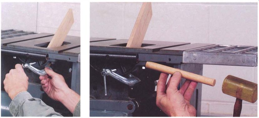
------------ To adjust the alignment on a contractor's saw, start by clamping
front and rear trunnions. Bolts holding the trunnions in place are attached
directly to the underside of the table.
------------ With bolts loosened, gentle taps using a hardwood dowel will shift the trunnions so the miter-gauge slot becomes parallel with the blade.
---------------
Bolts That Shift
One common annoyance when tuning up a machine is to get everything adjusted just right and then have parts shift out of line when you tighten the bolts. If that happens, check the underside of the bolt heads for burrs, paint, or rough spots and dress them using a file. Also check that the spot on the machine where the bolt attaches is smooth and paint free. The bolt should have a sturdy, burr-free, flat washer under the head in addition to any lock washer. Finally, grease the threads of the bolt and both faces of the washer before assembly. This is a good place for an antiseize grease.
------------
With the trunnions safely clamped, loosen three of the four bolts holding the assembly to the bottom of the table. The fourth one, at the front of the saw, should be left slightly snug to serve as a pivot. Adjust the alignment by tapping the rear trunnion bracket to rotate the arbor assembly into better alignment using a mallet and hardwood dowel (see the photo above right).
Once the dial indicator shows the alignment is correct, snug up the bolts and reconnect the drive belt. If the weight of the motor throws off the alignment, you'll have to readjust the trunnions to compensate. Remove the clamps when you are done.
Benchtop saws
The arbor assembly on a bench top saw is suspended from a pair of small hinges bolted to the underside of the table. Loosen the bolts, which can be hard to reach, leaving one slightly snug to serve as a pivot point (see the photo on the facing page).
Adjust the miter-slot alignment by shifting the bracket that isn't serving as a pivot. Use the dial indicator to measure the alignment, then tighten down the bolts when it is correct. Recheck to make sure the position hasn't shifted.
Aligning the Rip Fence
A rip fence is properly adjusted when it is parallel to the blade. If it isn't, the ripped board will have a burned or wavy edge and the chances of kickback increase. The procedure for checking the alignment of the fence is similar to the method used to check the miter-gauge slot.
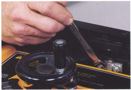
------------ A pair of small hinges bolted to the underside of the table
controls the miter-slot alignment on a benchtop saw. Reaching them can be
a chore.
Because many original equipment fences have design flaws that make them unreliable and difficult to align, a dozen or more aftermarket rip fences are available (although not all of them are much of an improvement). In my guide, the best design is the one by Biesemeyer, of which there are now several clones.
If the outfeed end of the fence is toed in toward the blade, the stock is pinched against the side of the blade during a cut, which creates a host of problems (see the illustration at right). Initially, the board will be hard to feed. Friction will burn the cut edge, and the blade will overheat. When the leading end of the stock reaches the back of the blade, it will be struck by the rising saw teeth, causing a ragged edge and a high risk of kickback.
If the outfeed end of the fence is toed out, the symptoms are distinctly different (see the illustration on p. 80). The kerf in the board, sandwiching the blade, will lead the stock away from the fence. Attempting to force it back will create a wavy edge on the board. The off-cut will drag against the side of the blade, leading to burning, chatter, and possible kickback.
Some rip fences are bolted to the head with two to four bolts, which when loosened allow the fence to be shifted into line. This style of fence is harder to adjust; you just have to keep trying to get it right. Some bolt type fences lock onto the front rail only, while others lock onto both the front and rear rails. Adjustment procedures are somewhat different. In Biesemeyer-style fences such as that shown in the photo on p. 80, adjusting screws are located behind pads at the outer ends of the fence's head.
Setting up this style of head is a joy. You just tweak the set screws until the fence is where you want it.
-------
Misaligned Rip Fence
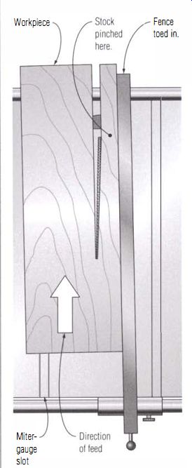
If the fence is toed in, the workpiece may become jammed between the back edge of the sawblade and the fence, burning the stock and increasing the risk of kickback.
--------------
Misaligned Rip Fence
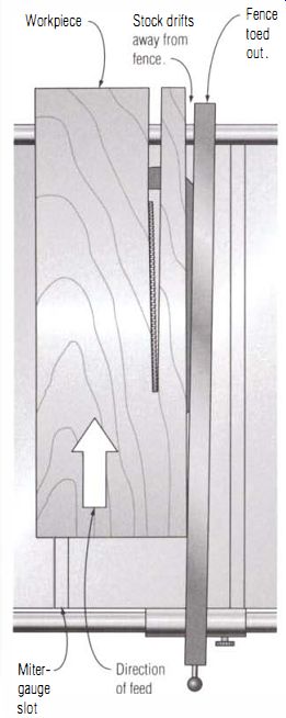
If the fence is toed out, the front edge of the workpiece will drift away from the fence. Attempts to push it against the fence will cause binding and possible kickback.
------------
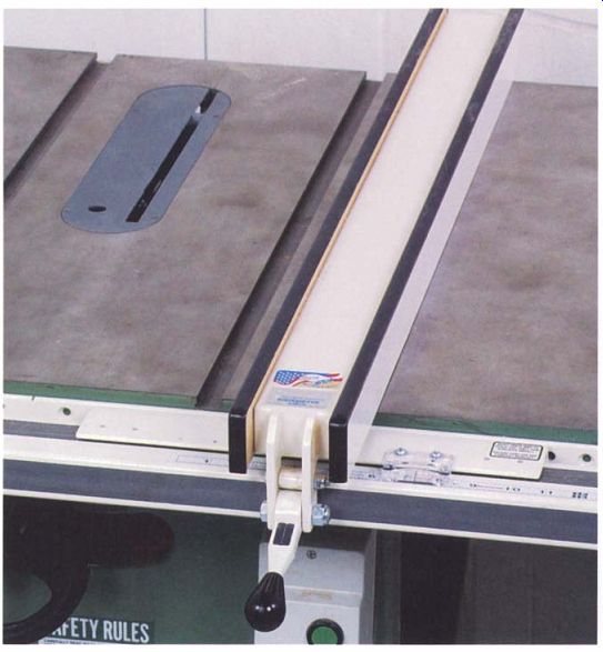
----------------- In this Biesemeyer-style fence, set screws behind nylon
pads on the head of the fence are used to adjust alignment.
CHECKING THE ALIGNMENT
Start the alignment procedure by unplugging the saw, removing the blade, and placing the fence on the side of the table you normally use for ripping.
Raise the blade-height adjustment to just below its highest position, and install the arbor plate with its marked face toward the fence.
Attach the dial indicator to the end of the notch in the block as shown in the photo on the facing page. Holding the block against the fence, move the fence toward the arbor plate so the hand makes a couple of turns and comes to rest at the 12 o'clock position. Lock the fence in place, then slide the block along the fence until it crosses the centerline on the plate and mark the intersection. Using a square, lengthen the mark.
Tap the indicator and plate a few times to make sure they've settled in and zero the indicator.
Next, pivot the plate to the other end of the opening and slide the block forward until the indicator tip again touches the centerline at the spot you marked earlier. You may have to raise the plate on a block to get the tip on the correct spot.
If the dial indicator doesn't read zero, the fence isn't parallel to the blade. When taking readings, lightly press the block against the fence and make sure that no sawdust is caught behind the block. Slightly flex the arbor plate with finger pressure to see which way brings the indicator back toward zero. This will tell you the direction the outfeed end of the fence will need to be adjusted.
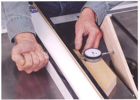
-------- The rip fence should be perfectly parallel to the plane of
the blade. Measure at the front and rear of the table with a dial indicator.
------------------
Adjust the lock Mechanism
Before tuning up the rip fence, clean, lubricate, and adjust the lock mechanism. The fence will only stay parallel to the blade if it can be locked in place without twisting. This also is a good time to make sure that the front and rear rails are straight and solidly bolted to the saw's table. If the front rail isn't perfectly straight, no amount of adjusting will keep the fence parallel to the blade as it is moved to a new setting.
---------------------
ADJUSTING FRONT- AND REAR-LOCK FENCES
To adjust front- and rear-lock fences, unlock the head after you have taken your initial measurements with the dial indicator. Set the indicator aside, then one at a time, loosen the bolts holding the fence to the head and retighten them until they are lightly tensioned. Leave the fence free enough to be tapped into alignment with light mallet blows. Once you have the bolts adjusted, tap the outboard end of the fence to bring it closer to parallel to the blade.
Lock the fence to the bar. If the pull of the lock causes the head and bar alignment to shift, you'll have to tighten up the bolts before you do this. Move the dial indicator back in place and compare the front and rear readings to see if the fence is properly aligned.
Repeat the procedure until the indicator shows the fence is aligned, then fully tighten the bolts.
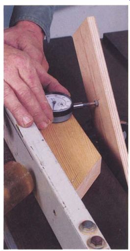
--------------- The rip fence is parallel to the blade when dial-indicator
readings at the front and back of the fence are the same.
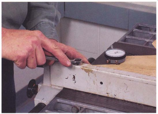
------------- Rip fences on contractor's saws often need adjusting after
loosening the bolts at the head .
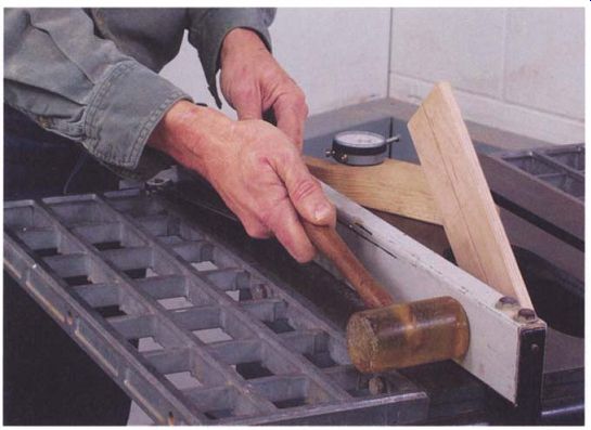
---------- A gentle tap is all that's needed to move the fence into alignment.
ALIGNING A SET-SCREW FENCE
If you have a set-screw fence, lift the fence off the front rail and flip it over on the saw table. Adjust either the left or right set screw to correct the fence's setting, then replace the fence and use the indicator to check the alignment. Repeat the adjustment procedure until the fence is parallel with the plate. Everything should be this easy.
On this style fence, the set screws also affect how tightly the fence locks onto the rail. If adjusting for parallel has made the lock setting too tight or too loose, advance or retract both screws equally to get the lock setting right, then recheck the fence's alignment with the blade. It may need a slight adjustment.
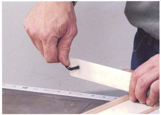
------ Set screws adjust the alignment of the T-style fence.
Tuning Up the Blade-Tilt Settings
Properly adjusted, the sawblade will be perfectly square to the surface of the table when it is moved all the way to its vertical stop. A second stop sets the blade at 45 degrees for cutting miters. The quickest and most accurate test for setting these two stops is a dynamic one: You cut the end off a board and check it for square or 45 degrees.
To do this test, choose a 3-ft.-long, clear, straight-grained piece of wood about 1 in. thick and 4 in. wide. It can be either hardwood or softwood. If you choose pine, it should be a dense, tight-grained piece that will cut cleanly.
Carefully plane one face of the board flat, since this test will be reliable only if the board sits perfectly flat on the saw's table. Once you have a flat face, plane one edge straight and square to the good face (this edge will ride against the miter gauge when you do the test cuts).
Place the board on the saw table with the planed face down and the squared edge against the miter gauge, then mark the exposed face of the board with a prominent V pointing toward the face of the gauge. Make all of your test cuts with the board in this position.
The only tools you will need are a square that you know is accurate and a few small regular wrenches or Allen wrenches for adjusting the stop bolts.
Mount a good-quality crosscut or combination blade on the saw for this procedure. The smoother the cut end of the board, the easier it is to judge the board's fit against the square.
SETTING THE 90-DEGREE STOP
The stops at 90 degrees and 45 degrees allow you to return to these settings quickly with a fair degree of accuracy. To check the 90-degree setting, start by cranking the handwheel until the tilt mechanism is against the vertical stop. Lock it and place the miter gauge in the slot you regularly use for crosscutting (see the photo at left below). Take a test cut off the end of the test board, trimming off about 1/2 in. of stock. Make sure the V on the board is visible and pointing toward the miter-gauge face. To check the cut for square, place the beam of the square on the planed (unmarked) face of the board and hold it up to the light to see if there is a gap between the freshly cut end and the square's blade.
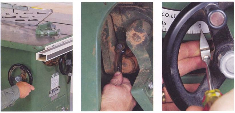
---------- Prepare to check the accuracy of the stop by setting the
saw to the vertical position and placing the miter gauge in the slot you regularly
use for crosscutting.
---------- The adjustment for the blade-tilt stop is generally tucked up inside the saw in a hard-to-reach spot. It can sometimes be reached through the slot in the front of the cabinet.
----------- Once you have the 90-degree adjustment set, adjust the tilt-stop pointer.
If the cut isn't square, adjust the stop bolt and tighten its locknut, then take another test cut. On most saws, the stop bolt is under the table and awkward to reach. Sometimes it can be reached through the slot in the front of the cabinet (see the center photo on the facing page). On a few saws, the stop bolts are set into the tabletop and are easily adjusted with Allen wrenches. These bolts don't use locknuts; they are locked by a nylon insert that prevents them from shifting.
Once the saw is cutting a square end on the test board, set the pointer against the angle scale to zero. For accurate readings, the pointer's tip should be close to the scale. You may have to bend it slightly to get a better fit.
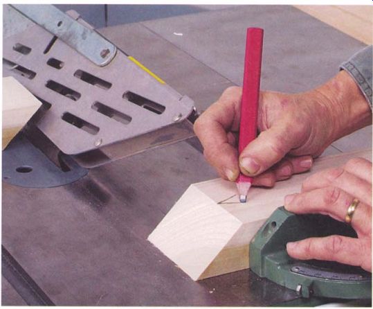
------------- Mark the end of the 45-degree test cut with a small V.
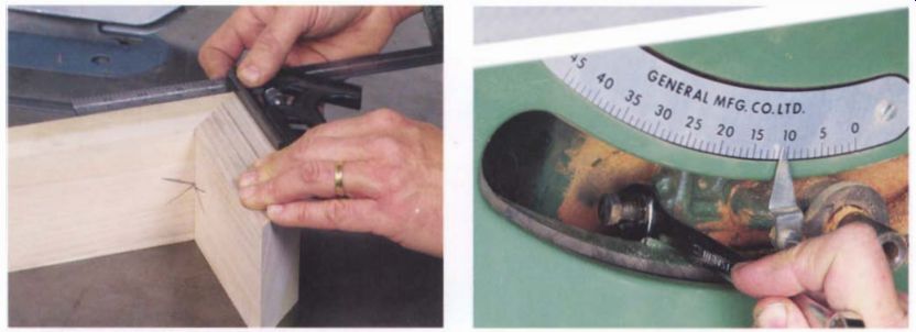
------------- The two 45-degree test pieces should mate at exactly 90 degrees.
------------- Tilting the blade back toward vertical may be necessary to access the 45-degree stop screw.
SETTING THE 45-DEGREE STOP
You can use essentially the same procedure for checking the 45-degree stop. An accurate check, however, requires two test pieces cut at 45 degrees, not one. First, tilt the blade until it reaches the stop, lock it, and place the miter gauge on the side of the table the blade tilts toward. Take a test cut, trimming about )If in. off the board, then make a small V mark on the board, pointing toward the end you just trimmed off (see the photo below). Slide the test board over 4 in. and take another cut. Setting the 4-in. piece aside for a moment, again make a mark on the test board pointing toward the end you've just cut. Then take the 4-in. cutoff and the main board and arrange them to make a corner with the V's pointing at each other at the inside corner of the joint. Place a square on the outside of the corner and check if it is a precise 90-degree corner (see the photo at left above). If the test corner isn't square, adjust the stop screw, lock it, and make a new test joint. On many saws, the 45-degree stop screw can be difficult to reach. If so, try tilting the blade back toward vertical to improve your access to the screw and then return it to the stop for a new test.
Checking the Miter Gauge
Of all the steps involved in tuning up a table saw, adjusting the stops on the miter gauge is the easiest. The gauge should help you make precise 90-degree crosscuts and 45-degree miters. The simplest and most accurate method of aligning the gauge is to make test cuts and then check the cut end of the board with an accurate square.
Before adjusting the gauge, make sure that any shop made wood facing is straight, square to the table, and solidly attached to the gauge's head casting. Often the bar will seem loose in the miter slot but this rarely has a significant effect on accuracy because the bar will settle into the same orientation in the slot each time a cut is made.
Almost all original equipment fences are adjusted by turning stop screws that bear against a small hinged tab in the trailing edge of the bar.
This style of gauge is frequently thrown out of alignment because the tab bends easily. Handle the gauge with care and check it before making critical cuts.
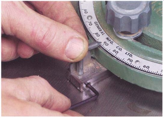
--------- Loosen the set screw to adjust the pointer on the miter gauge.
If adjusting the stops on the gauge won't produce smooth, square crosscuts, it is likely that the miter-gauge slot is not parallel to the blade.
The only solution is to reposition the table as outlined in "Aligning the Blade and Miter-Gauge Slot" on p. 73.
If you are only going to check the miter gauge for square cuts, you'll need one board around 1:1 in. thick, 3 in. to 4 in. wide, and 2 ft. long. If you also want to set the 45-degree stops, you will need a second board the same size. The stock can be either hardwood or a tight-grained softwood with no large knots. You should plane the stock flat and even in thickness and carefully joint one long edge straight and square. Mark V's on both wide faces of the board pointing to the jointed edge. Always make your test cuts with this edge against the miter gauge.
Place the gauge in the slot you regularly use for crosscutting, then place the test board against the gauge with the good edge against the face and trim VI in. off the end. Using the square, check the edge and make the appropriate adjustment on the stop bolt. When the cut is square, adjust the pointer to 0 degrees (see the photo above). To adjust the 45-degree setting, turn the head of the gauge toward the blade and lock it against the stop. Take one of the boards and trim its end off, making sure you keep the good edge against the face. Make the same cut on the second board. When the two boards are butted together, they should form a 90-degree corner. Adjust the stop screw, if needed, until it is exactly 90 degrees.
-------------------
Check Miter Slots for Parallel
The two miter slots in the saw's table may not be exactly parallel or precisely the same width. If you tune up the gauge in the left-hand slot, it may need to be readjusted when you use it in the right-hand slot.
--------------------
Prev. | Next | Article Index | Home