It is nearly impossible to build furniture with lumber that is not straight, flat, and square-edged, and the jointer is at the heart of careful stock preparation. The mechanics of a jointer are simple, but tuning and maintaining this tool can be challenging. A jointer requires very precise adjustments, within a few thousandths of an inch. When it is out of whack, a jointer will snipe the ends of boards, taper stock like a clapboard, create curved edges, and tear the surface.
Poor performance is most often due to several small misalignments, not just one. It is usually much more efficient to undertake a complete tune-up rather than try to isolate a single fault. This is especially true if the machine has never had a top-to-bottom check of its various parts.
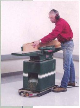
----------A properly tuned jointer will produce straight, square
edges on stock, the first step in making quality furniture.
---------- Even minor misalignments between parts of a jointer make it
difficult to produce flat, square-edged stock.
A thorough, systematic tune-up is the best approach to getting the machine in top shape.
Anatomy
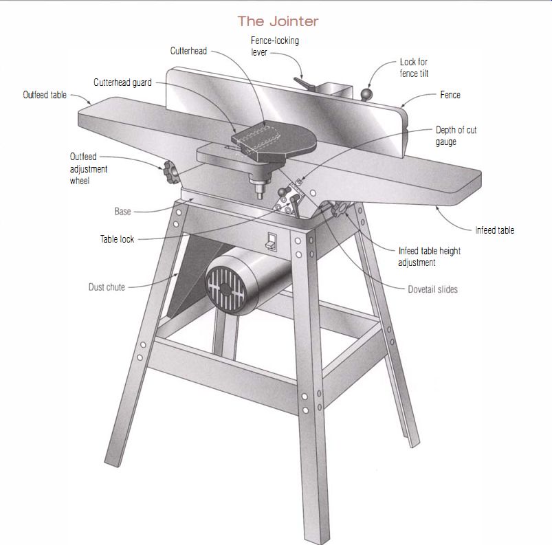
A jointer has an infeed and an outfeed table, both of which typically can be adjusted for height (on some low-priced machines, the outfeed table is fixed). The tables flank the central cutterhead, which is mounted in the base casting (see the top left photo on p. 18). A fence along the back edge of the tables guides the stock, and a spring-loaded guard covers the cutting head.
On most American-made jointers as well as on their overseas knockoffs, the tables slide up and down sloped dovetailed ways in the base casting as they are adjusted in height (see the top right photo on p. 18). The dovetails need to be loose enough to slide but tight enough to hold everything in alignment. To achieve the proper fit, the dovetails are adjusted by set screws bearing on gibs (see the bottom photo on p. 18). On many European machines, table height is set with pivoting, parallel arms, an elegant design that works very smoothly and is less prone to problems.
When a board is jointed, the infeed table and the fence guide the stock as it crosses the cutterhead. The outfeed table picks up the freshly planed surface and guides and supports the stock as the pass is completed.
The finished surface on the stock is only as straight as the path the wood takes across the cutter. If the tables aren't flat or if they do not line up with the cutterhead and each other, the path of the wood won't be straight and the finished edge of the board is bound to be crooked.
A full tune-up starts with cleaning and lubricating the jointer and checking the cutterhead bearings. Next, the tables are checked for flatness and the fit of the dovetail slides is adjusted. Once the slides are adjusted, the tables are shimmed if needed to line up with each other. The final part of the process is installing new knives in the cutterhead and fine-tuning the outfeed table height and the fence alignment.
You will need a set of feeler gauges, a small square, and a short straightedge (the blade from a combination square is ideal ). If the tables need shimming, a 6-in. dial caliper would be handy for measuring shim stock, but the job can be done without one. To check the tables for flatness, you'll need long machinist's straightedges or shop made master bars in two lengths. Later, when you are ready to change knives, you may want to make a magnetic jig to hold the knives in place as well as a very simple tool to locate top dead center for the cutterhead.
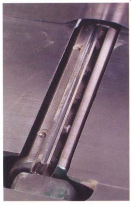
-------- Made from steel or aluminum, the cutter head holds two or more
replaceable knives.
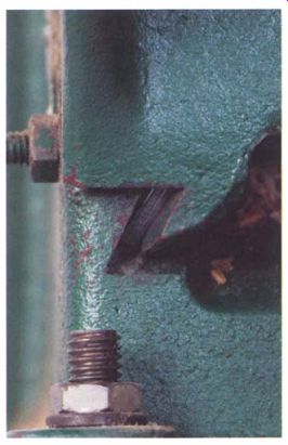
----------- The end of the flat steel bar called a gib can be seen in this
end view of the dovetail table slides. The gib-adjusting screw and its locknut
is on the left; the bottom bolt and nut attach the jointer to its stand.
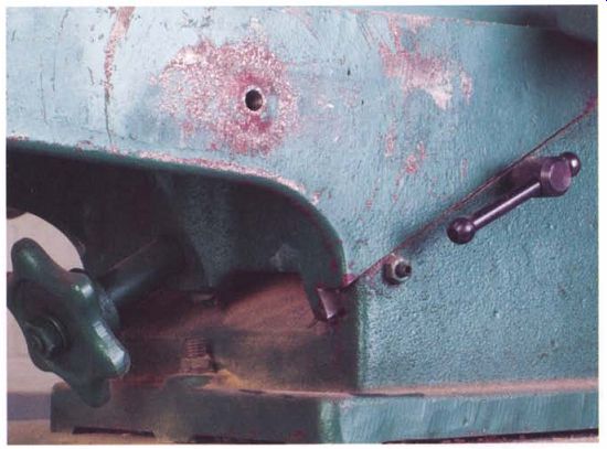
------------ Table height is set by sliding the tables on sloped ways.
On this machine, a small T-handle locks the table, while turning the handwheel
changes the height.
TROUBLESHOOTING
Because a jointer only has one function-to straighten the surface or edge of a board-the list of possible problems affecting performance is fairly short. • The edge of a planed board is concave after repeated passes. In this case, the outfeed table is probably too low. If raising it doesn't correct the problem, the outfeed or infeed tables may be low at their outboard ends. Tightening the gibs normally solves the problem. The remaining possibilities for cutting a concave edge are worn slides and a warped table, both of which can often be corrected with shims .
• The jointer is cutting a convex edge. Here, the most likely cause is dull knives that are no longer removing as much stock as they used to. A second possibility is that the outfeed table is too high. A rare possibility is that one of the tables has warped upward or caked grease has somehow lifted one of the tables off of its slides.
-----------
Always Turn Off the Machine
Although it seems impossible, a machine can inadvertently be turned on while you are working on it.
To be absolutely sure the machine is turned off, always unplug any machine before attempting setup or maintenance operations.
------------
Setting Up the Machine
For safety, the jointer should be unplugged during any adjustments or repairs. If you are planning to check and adjust the tables, remove both the fence and the blade-guard assemblies. On most jointers, this is a simple job. If you are just doing a blade change, the fence can stay in place but the guard should be removed.
Use a shop vacuum to remove loose sawdust from the jointer. Most of the dust and chips inside the machine won't be picked up by the vacuum, however, and should be dislodged by switching the hose on the vacuum to the exhaust side. I don't recommend using compressed air because dust and chips may be forced into the bearings and slides where they will eventually cause trouble.
CHECK THE BEARINGS
Cutterhead bearings and the drive pulley should be checked first, since a bad bearing must be replaced before the tune-up can go any further.
Typically, replacing bearings on a jointer is not a difficult job.
Check the bearings by rotating the cutterhead a couple of revolutions.
There should be no roughness, sticking, or noise. Next, lift up sharply on the pulley several times as you rotate the shaft by quarter turns (see the photo on p. 20). If you feel or hear a clicking sound, either the bearings are worn or loose in their housings or the pulley is loose and should be tightened.
Pay particular attention to the pulley. Small home-shop jointers seem especially prone to having it come loose. Check the pulley regularly because a loose pulley can quickly chew up the shaft. If the drag of the belt and motor makes it hard to judge the condition of the pulley or the bearings, remove the belt.
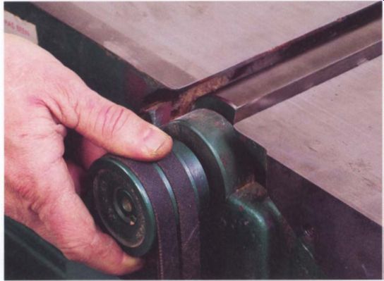
---- By rotating and lifting the pulley, the jointer's bearings and pulley
attachment can be checked for wear and looseness.
LUBRICATION
If the table-height adjusters are hard to turn, it is usually because the grease on the dovetails has dried out. Before taking the jointer apart for regreasing-a major job-try spraying a penetrating oil such as WD-40 onto the slides as you work them back and forth with the adjusting screws (see the top photo on the facing page). With luck, the oil will mix with the grease and revive it. You should also spray oil on the threads of the adjusting screws, reaching through the gap under the tables behind the adjusting handles.
If the height adjusters are still hard to turn after applying oil, either the gibs are too tight or the dovetails are clogged with dirt and rust. Try to adjust the gibs as explained in the next section. If that doesn't solve the problem, the tables must be removed so they can be cleaned and the slides greased.
Removing Tables for Maintenance
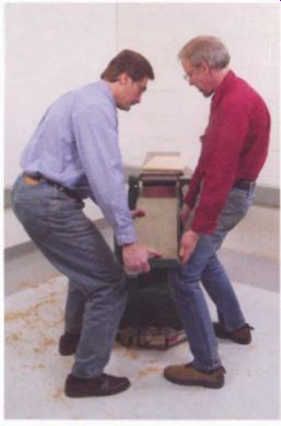
To clean and grease a jointer, slide the tables off the dovetails, but keep in mind that cast iron is heavy. A table on an 8-in. jointer can easily weigh more than 100 lb. You should have an assistant when you remove or install the tables on all but the smallest machines. Tackle one table at a time and reinstall it before moving on to the second one.
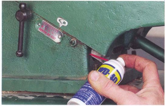
------------ Using a penetrating oil to free up a jointer's tables is
an effective, although temporary, alternative to taking the machine apart
to clean and regrease it.
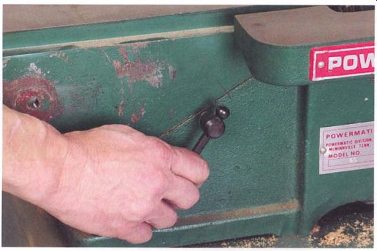
------------ Before disconnecting a table's height-adjusting screw, the
gibs should be locked to prevent the table from sliding free and crashing
to the floor.
------------
Choosing Lubricants
Penetrating oil is a temporary fix at best because it evaporates and gets absorbed by dust after a few days. Old grease doesn't lubricate as well as fresh grease, risking accelerated wear of the dovetails. You can improve the situation somewhat by trying to work in some thicker oil. But eventually, all jointers should be disassembled for a thorough cleaning and regreasing.
-----------
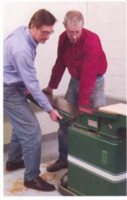
--------- Once the last gib screw is loosened , the table slides off the
dovetailed ways that hold it to the base casting. Even on a 6-in. jointer,
the table can be too heavy for one person to handle.
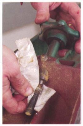
------------- Clean off the threads of the height adjusting screw. The
threaded block may need soaking in paint thinner to remove old grease and
debris.
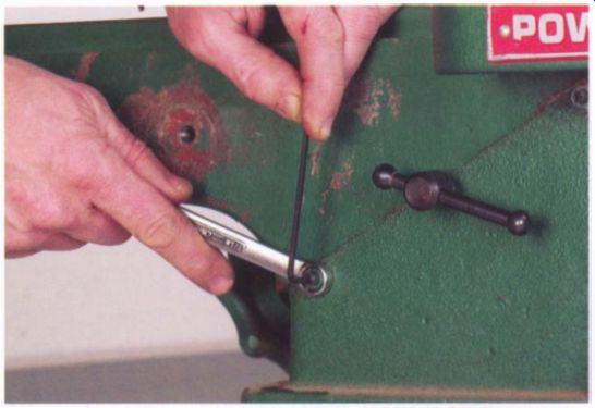
---------- The final step before removing the table is to loosen the top
and bottom gib-adjusting screws. Now only the center screw is holding the
table in place.
REMOVING TABLE EXTENSIONS
Begin by removing any bolted-on table extensions that support the guard or fence. Next, on most machines, the block that the height-adjusting screw threads into must be removed. The block is bolted to the base casting and projects up into the wedge-shaped area under the table.
Before unbolting the block, you must make sure the table won't slide by firmly tightening down the locking lever (see the bottom photo on p. 21) . On machines that don't have a locking lever, tighten the center gib screw. This is important for your safety: If the table isn't locked, it will slide free and drop to the floor the moment the block is unbolted. On some jointers, it is possible that the weight of the remaining table will tip the machine over when the opposite table is removed. For safety, have a support under the table you are not removing.
Bolt heads holding the block in place are on the underside of the base casting and can be difficult to reach. In some cases, the stand will block your access. Typically there are two hex-head bolts holding the block but they may be Allen heads. Once the block is unbolted, you can remove the table.
Leaving the center or lock bolt for last, back off the top and bottom gib screws a couple of turns (see the photo above). Now only the center screw or lock bolt is holding the table in place. Steady the table and release this last bolt, then slide the table down and off the dovetails (see the top photo at left). On some machines you may have to slide the table up over the cutterhead to remove it. Set the table, dovetails up, on a pad of plywood on the other table of the jointer, making sure the machine won't tip over from the weight.
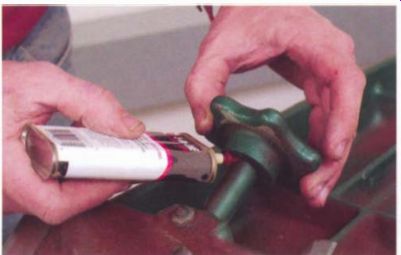
-------- Lubricate both ends of the shaft of the adjusting screw where
it goes through the bushing in the table.
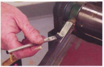
---------- Using a small, disposable brush, apply grease to all sliding
surfaces of the slides, a total of eight faces: four on the table and four
on the base casting.
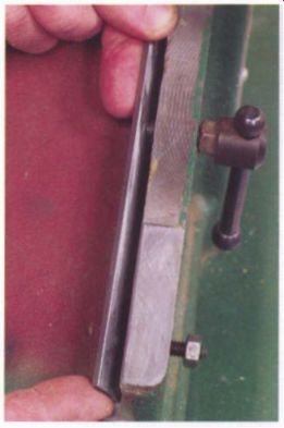
------ There is only one correct orientation for the gib, where the tips
of the screws match the indentations in the side of the gib.
Before sliding the table back in place, determine how the gib should be installed.
------------------
Filing Gib Surfaces
GIB SURFACES ARE OFTEN IN POOR CONDITION.
To remove high spots without changing the gib's shape, I use a small, flat file on the gib, holding it flat on the surface (see the photo at left below). Use the file to bevel the edges at each end of the gib to make it slide more easily, and use a triangular file on the bearing surfaces of the dovetails (see the photo at right below). Keep the file flat on the machined surfaces of the casting and bear lightly: You just want to polish things up and remove burrs.
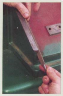
The faces of the gib often are burred or uneven from the pressure of the
adjusting screws. Gibs should be dressed with a flat file and have its edges
beveled.
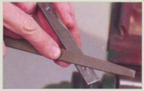
Use a triangular file to pass lightly over both the flat and angled surfaces
of the dovetails to remove burrs and rough spots.
-------------------
Use paint thinner and rags to remove old grease on the jointer's slides.
A brush or Scotch-Brite pad will help on stubborn spots. In addition, remove the threaded block from the adjustment screw and clean up the adjustment screw and the gib (see the photo at left). Once everything is clean, I always go over all the sliding surfaces with a file to remove burrs and rough spots.
Lubricate the height-adjusting screw where it goes through the bushing in the table with light oil, applying it at both ends of the bushing (see the top left photo). White lithium grease is best for the sliding surfaces of the dovetails. It can be applied with a small brush (small, disposable brushes called flux or acid brushes are perfect). Be sure to grease both the flat and the undercut beveled surfaces of the dovetails on the table and then grease the height-adjusting screw.
Once the table is done, grease the slides on the base casting (see the top right photo on p. 23 ). On some jointers, only the ends of the slide are bearing surfaces; the middle section is machined slightly lower and doesn't need greasing. Don't forget to grease the inside surface of the dovetail.
---------- Slide the table back onto the base with care to prevent jamming
the dovetails. On larger machines, having a helper is a must.
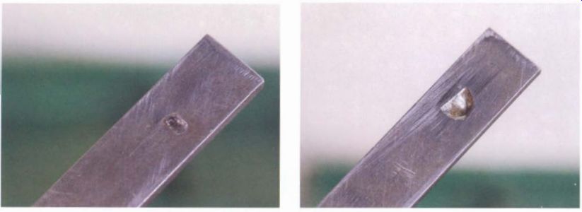
--------- The sharpened tips of the gib screws typically make small indentations
in the gib. When reassembling the jointer, make sure the screws engage these
marks.
--------- On some gibs, a small pocket is mil led in the gib on the face opposite the adjusting screws. This pre vents the pressure of the screw from creating a high spot that would cause the gib to dig into the dovetail. Don't mistakenly install the gib with the pockets facing the screws.
REASSEMBLY
Begin reassembly by threading the adjusting block onto the adjusting screw. Run it halfway down the thread. Match up the indentations on the back of the gib with the gib screws to be sure you will be sliding the gib back in its proper orientation (see the bottom right photo on p. 23 ). Some gibs have relief cuts that go against the dovetail surface; they are not pockets for the tips of the gib screws (see the photos below). Note the proper orientation of the gib and put it where you can reach it easily after you slide the table back in place. As long as you greased the dovetail surfaces well, you don't have to grease the gib. It will be easier to handle if you don't.
It is important to have a helper when reassembling the table. As you flip the table over, make sure the threaded block is rotated to its correct position. Carefully fit the dovetails together and slide the table back in place (see the photo at left). You may have to reach under the table to position the threaded block if it catches on the base casting.
After you have slid the dovetails all the way home, hold the table in place and slip the gib into place, being sure to have the correct side facing the gib screws. On most machines, the end of the gib should come flush with the end of the base casting. You can check the gib's position by removing one of the adjusting screws and peering through its threaded hole in the base casting. If the gib is properly positioned, you will see the indentation from the screw point centered in the hole.
Once the gib is in place, lock the table by tightening the center lock handle or the center gib screw. For added security, tighten the top and bottom gib screws until they are snug against the dovetails. It should now be safe to release your grip on the table, but be careful when you let go.
With the table secure, turn the height-adjusting screw to position the block over its mounting holes in the base. Reaching up from underneath, thread the bolts back into the block and tighten them securely (this is often easier said than done). With the machine greased and reassembled, it's time to move on to a much more pleasant job: adjusting the gibs.
Gib Tune-Up
Gib adjustment is critical. When gib screws are loose, the tables drop at their outboard ends, throwing them out of alignment and making it impossible to create a straight edge on a board. Gib screws are not tightened equally. The screw nearest the cutterhead is tightened first. It is adjusted to apply the most pressure because the top end of the gib must counteract the weight of the table.
SCREW ADJUSTMENT
Begin by backing off all the gib screws a half turn to a full turn to leave the gib slightly loose but not so loose that the gib slides out of position.
The table should now move very easily with the table-height adjuster. If the table binds, you should track down the cause and correct it now.
Tighten the screw nearest the cutterhead while running the table back and forth with the height-adjusting knob (see the photo at left on p. 26). As you tighten the screw, the table will become harder to move. When this first screw is properly adjusted, it should take moderate effort to move the table. Once the adjustment feels right, hold the screw against turning and snug up the locknut (see the photo at right on p. 26). Tightening the locknut may change the pressure on the gib, so you should check the setting and readjust it if necessary.
Once you have the first screw adjusted and locked, repeat the procedure with the screw on the opposite end of the gib, tightening it to add only slightly to the force it takes to move the table. If your machine has a center screw with a locknut, adjust it last and with only light pressure against the slide. If the center screw is fitted with a knob so the table can be locked during regular operations, just leave it loose for now.
After you finish adjusting the gibs on one table, repeat the procedure on the second table. When all the gib screws are set correctly, you should not feel that you are straining either the machine or yourself to move the tables, but there should be no free play in the gibs. Getting the gibs adjusted just right is a matter of both technique and feel, much like tuning a musical instrument.
Adjusting Tables for Flatness
It may come as a surprise, but cast iron warps easily, typically because the casting process was faulty or because the rough castings were not allowed to age long enough before they were machined. Like wood, cast- iron tables can cup, bow, and twist. And just as with wood, checking for warp is done using a straightedge laid across the table's surface. The accuracy required is well beyond the tolerances of woodworking, however. You will need a straightedge that is accurate to within a couple of thousandths of an inch over its length.
I adapted a machinist's technique for creating a straightedge from inexpensive materials. Technically, the tool isn't a straightedge because only three slightly proud screw heads along one edge are precisely in line.
More properly, the tool is called a master bar.
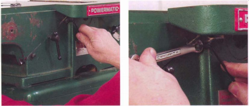
-------- Tighten the top gib screw first because the leverage from the
table is concentrated entirely on this end of the gib.
---------- When the pressure on the gib feels right, lock the gib screw's lock nut and then recheck the table's motion. Tightening the nut may affect the setting.
------------
Accurate Straightedges
When adjusting tables for flatness, avoid using builder's levels because they are not reliable.
Machinists use precision steel straight edges that are designed for just such applications, but a 4-ft. model may cost $200 and a steel straightedge can be rendered useless in one heart stopping drop to the floor. If you invest in one, treat it with great care.
-------------
MASTER BARS
Although it may not seem possible, three screw heads along the length of a master bar can be aligned with each other so they are within thousandths of an inch of being in a straight line, creating an inexpensive straightedge whose accuracy rivals a costly machinist's tool.
A master bar is made from MOF, which is readily available and inexpensive. A master bar is actually made as a three-bar set in which one bar is designated as the master bar. The other two bars are nearly identical and are called setup bars. The setup bars are marked with the letters A and B. PREPARING THE STOCK
The bars shown are made from 1 1/4-in.-thick MDF. Foot-wide bull-nose MDF shelving is convenient; it is easy to rip a piece into narrower strips on a table saw. Cabinet-grade plywood also can be used, provided it does not have any bow that would prevent it from lying flat on a bench top while the screws are being adjusted. Plywood has one advantage: It's lighter.
Bars up to 3 ft. long can be ripped to 4 in. wide. Bars up to 6 ft. long should be 6 in. wide. If you need an 8-ft. bar, it should be at least 9 in. wide and made from plywood for ease of handling. After cutting the bars to size, round off their sharp edges to make them more comfortable to work with.
For checking the flatness of a machine's tables, make the bars as long as each table. For checking the overall alignment of the jointer, you will need a bar that spans the full length of the machine.
All three bars in the set are cut to the exact same size. In each set, cut the top corners off of one bar to make it easier to spot as the master bar (this is the only difference between the master bar and the setup bars). On the machine-length bars, cut the top corners of the master bar back with a long taper to reduce the bar's weight.
Each bar has three 1 5/8-in.-long fine-thread drywall screws set in one edge. The outer screws are placed 1 in. from the ends. On the shorter bars for checking table flatness, the third screw is placed at the bar's midpoint.
On the machine- length bars, the third screw is located so it falls on the infeed table 1 in. from the cutterhead opening. Two 1-in.-dia. finger holes are drilled midway between the screws, close to the working edge of the bar.
MAKING THE BARS
After cutting the stock for the bars to size, clamp the three bars together and use a square to mark the center lines of the screw holes on all three bars at once (see the top photo at right). Use a fairly large drill bit to make pilot holes for the screws to prevent the edges from splitting. It's a good idea to test the bit and screw combination on a piece of scrap.
For the bars to work properly, it is important that the screw holes be square to the edge of the bars. Since it would be difficult to set up the bars on a drill press, make the jig shown in the top photo on p. 28 to guide the drill. For accuracy, use a drill press to make the hole in the jig's hardwood guide block before attaching it to the jig's larger fence piece. You can hold the jig by hand against the side of the bar while drilling the holes (see the photo at right).
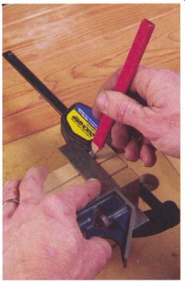
----------- To make sure that screw spacing is the same on all three bars
in a set, clamp the bars together and lay out the holes on all three at once.
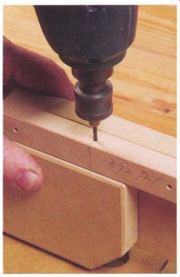
--------------- Line up the mark on the side of the jig with the line
made earlier across the edge of the bar using a square. This ensures that
the hole is precisely located.
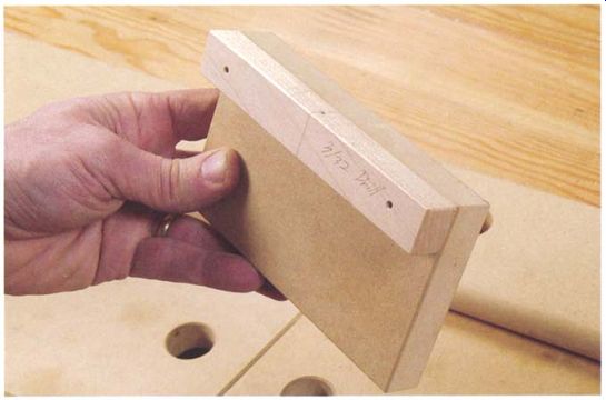
-------- A hole drilled in the hardwood strip on the side of this jig keeps
the bit square to the edge of the bars when drilling pi lot holes for the
drywall screws.
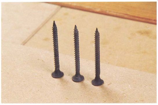
---------- To check that screw heads are even, stand them point up on
a smooth surface and take a close look.
A crooked screw head also would throw off the bar's accuracy. Remove any burrs on the screw heads with a few passes on a file or sharpening stone and then stand the screws on their heads on a smooth surface such as a scrap of MDF (see the bottom photo above). Look at the screws from the side to see if they are straight, sighting across the upright edge of a square if you don't trust your eye. Look at the screws from both straight on and from one side to check for square in both directions.
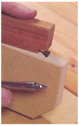
The screw heads should all stand proud of the bar by about y.; in. A simple way to set the screw height is to take a scrap of wood and cut a y.; -in. -deep notch in one corner. Set the block on the edge of the bar and adjust each screw in or out until the face of the notch just passes over the screw's head (see the photo at right). Once you have three bars with three screws in each, mark the two setup bars with the letters A and B and you are ready to fine-tune the screw height.
Check each table by placing the master bar along the table's back edge and then along its front edge. If the tables are bowed, use a feeler gauge to measure the gap under the bar (see the photo below). A gap of up to 0.005 in. is acceptable on a mid-sized machine. Beyond that, you'll start having trouble getting really straight edges on the boards you joint. After checking along the front and back edges, place the master bar on the table diagonally. Here again the gap should only be a few thousandths of an inch.
There is no foolproof or easy fix for a table that is out of flat. If the machine is still under warranty, the best course is to contact the manufacturer. Having the tables re-machined is possible, but it is likely to be very expensive. But warped cast iron can sometimes be shocked back into alignment. To do this, remove the table from the machine and prop it up between blocks on the floor, then stand on the casting and give a small jump. If you are lucky, it will straighten out. If not, try again with a slightly bigger jump. Be careful: Too much enthusiasm can crack the casting and you car, twist an ankle. This technique works more often than you might suppose, and it is actually recommended by one manufacturer for straightening warped jointer fences.
----------- A feeler gauge slipped between the screws on the master bar
and the table's surface will give you an accurate measure of how much the
table is warped. It should be no more than a few thousandths of an inch out
of flat.
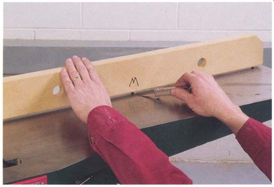
----------- A block with a 1/4-in. notch in one corner makes it easy to
ad just all the screws to project equally.
Storing MDF
For the short amount of time a master bar made of MDF is used during a tune-up, it works as well as an expensive machinist's straightedge. Be sure to store the bar flat between uses; it will take on a bow if it is left leaning against a wall.
----------------
Adjusting a Master bar
ADJUSTING A SET OF BARS TO GET THE SCREW HEADS INTO a perfectly straight line is a four-step procedure that you will repeat two or three times. Since each step requires a slight adjustment of one or two screws, the entire process will take just a few minutes.
The only finesse required is in judging whether there is a slight gap between the center screws when you pair up a set of bars. If the screws are high, the bars will rock slightly as you alternately pull the bars together with the finger holes on either end of the bar. Even if the screws are high by just a thousandth of an inch, the rocking can be seen, felt, and even heard because the outer screws will click as they're brought together.
By comparison, the only clue to a gap between the center screws is visual, so it helps to have a good light and a light-colored background under the center screws as you make the adjustments. If you are making an adjustment to close a gap, the most efficient approach is to overshoot the adjustment slightly to make the bars rock and then back off the screw being adjusted until the rocking just disappears.
To get a feel for how the procedure works, start the first adjustment with the center screw on the master bar slightly low. If you set the initial screw heights with a notched block, the screws may already be quite close to being in line, so turn the center screw on the master bar in one turn to be sure it is low. Once you have a feel for the procedure, you can start with the center screw in the master bar at any height. Note that in all cases only the height of the center screws are changed when adjusting a set of bars.
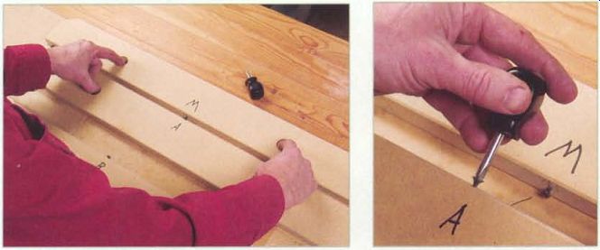
---- 1. Place bar A and the master bar together and adjust the center
screw on bar A to make all three pairs of screws touch.
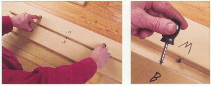
------- 2. Place bar B and the master bar together and adjust the center
screw on bar B to make all three pairs of screws touch.
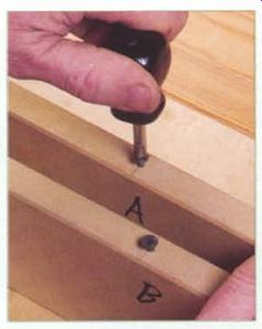
-----3. Place bar A and bar B together and equally adjust the center screws
on both, both in or both out, the same number of turns to make all three pairs
of screws touch.
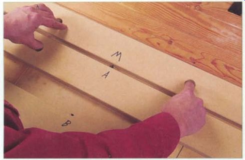
---------4. Place bar A and the master bar back together. This time adjust
the master bar's center screw until all three pairs of screws touch. Do not
adjust the screw in bar A.
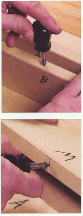
Repeat steps 2, 3, and 4 until you find that there is no need to make any
adjustments. At that point the screws on all three bars are in nearly perfect
alignment and the master bar is ready to use.
----------------------
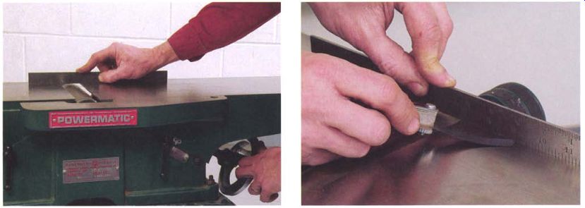
---------- The first step in checking the crosswise alignment of the jointer
is to bring the tables level with each other along the back edge of the machine.
-------------- To check whether a straightedge is actually touching both tables evenly, try to slide a very thin feeler gauge, 0.001 in. or 0.002 in. thick, beneath the straightedge along its length .
Shim Stock----Brass is the best material for shimming the dovetails because it will not tear or compress as aluminum can and it won't dig into the cast iron as steel shims will. Assortments of small brass shims are available at most hobby shops for just a few dollars.
Machine-shop suppliers also sell brass shim-stock assortments. The aluminum in soda cans is relatively hard and can serve as shim stock, but it is of limited use because it comes in only one thickness, normally around 0.005 in.
CROSSWISE TABLE ALIGNMENT
The next step is to test the crosswise alignment of the infeed and outfeed tables where they flank the cutterhead. If the tables don't line up crosswise, facing wide boards will create a wedge effect noticeable after a few passes. Your stock will start looking like a clapboard-thinner along one edge than the other.
Begin by raising the infeed table until a 12-in. metal straightedge laid on that table clears the cutting head when the knives are rotated out of the way. Now place the straightedge close to the back edge of the infeed table and extend it over the outfeed table by a few inches (see the photo at left above). Raise the outfeed table until it just touches the straightedge.
As a quick check that the straightedge is evenly touching both tables, run the thinnest blade of the feeler gauge set along the length of the straight-edge where it contacts the tables. It should not be able to slip under the edge anywhere along its length (see the photo at right above). Next, move the straightedge to the front edge of the tables and check if it still touches both tables. If there is no gap, the tables are aligned. If there is a gap of more than a couple of thousandths of an inch when measured with a feeler gauge, the tables need to be brought into alignment by shimming.
SHIMMING
Shims are used to fine-tune the relative positions of the parts of a machine. They are typically placed between parts that do not move once they are bolted into place, but this is not the case with jointer tables.
Here, shims must be placed between the sliding surfaces of the table and the base casting. Although you could shim either table to correct a misalignment, shimming the outfeed table is the better option because it is moved less frequently, so shims are less likely to wear out or work loose.
If the outfeed table is cast in one piece with the base, you have no choice but to shim the infeed table. A third possibility is that the outfeed table is a separate casting bolted onto the base. This style of machine can be shimmed by loosening the table's mounting bolts and slipping the shims between the base and table.
To avoid twisting the tables, shims are always used in pairs of equal thickness. To adjust the tilt across the table, place the shims at both the top and bottom ends of one slide. To adjust the lengthwise tilt of a table, place the shims at the top end or bottom end of both slides.
Shims should be an inch or two long, around one-sixth of the total length of the slide. You only need to pick up the ends of the slide to support the table properly. The width of the shim should be enough to cover the width of the slide with an additional 0.5 in. sticking out the side for easy handling (see the photo at left below). This tab can be folded down against the side of the machine once you are done, allowing a quick visual check that the shim hasn't shifted out of position (see the photo at right below). You can easily cut aluminum or brass shim stock with a good pair of scissors.
To adjust the crosswise alignment of the tables, cut two shims out of stock that is close in thickness to the amount of misalignment you measured with the feeler gauge. To insert the shims, back off the table's gib screws a turn, lift up on the low edge of the table, and slip the shims into place. Before installing the shims, give them a light coat of grease for lubrication and to keep them from slipping out of position while the gib screws are being adjusted. Once the shims are in, adjust the gib screws for a good sliding fit and recheck the table's alignment across the cutter opening.
You may have to experiment with shim thickness a few times before getting it right.
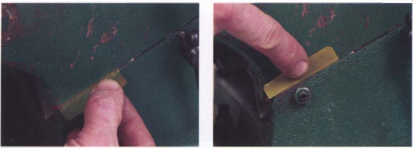
------------ Shims on a jointer slip between the table slides and the machine's
base. Cutting the shim oversize leaves a tab that's useful in the positioning
process.
------------- Once the tables are aligned, the projecting edge of the shim can be folded up against the side of the table. Later, the tab will make it easy to check whether the shim has moved.
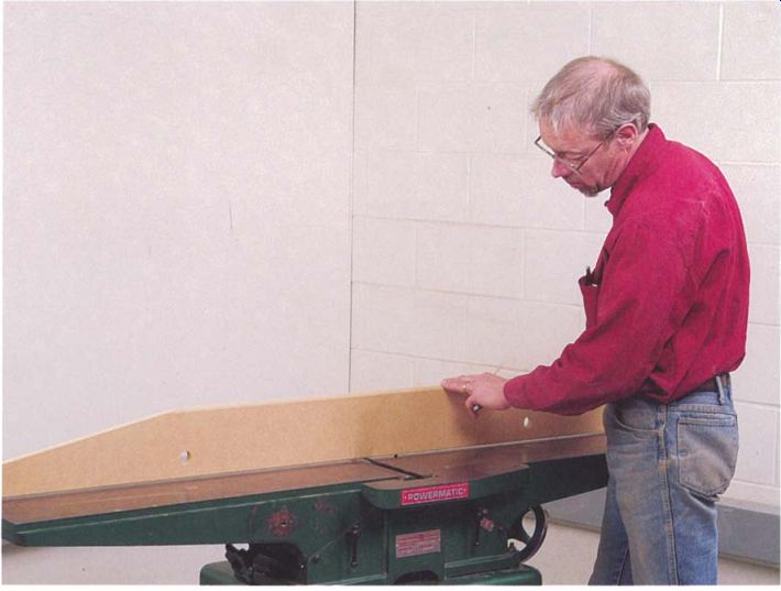
---------- It is fairly common for jointer tables, which have a lot of
overhanging weight, to sag at their outboard ends. A master bar as long as
the machine is used to check whether tab les are in the same plane.
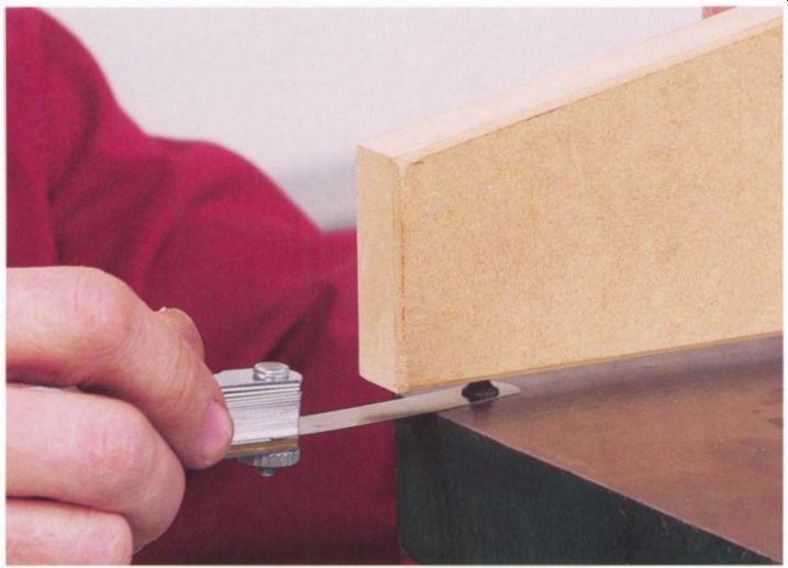
----------- Using a feeler gauge, check the gap under the bar screws. If
the gap is more than 0.005 in., shim the table to bring it back in line.
LENGTHWISE TABLE ALIGNMENT
Because of the tables' weight and long overhang, it is fairly common to find that the ends of the tables have dropped, causing the machine to be high over the cutterhead. This condition will cause a concave cut in the edge of boards when they are jointed. Before checking the machine's alignment with a master bar as described next, always make sure the gibs are tight.
To check the lengthwise alignment of the tables, you'll need to make a long master bar using the method described on pp. 26-3 1. This large bar is 6 in. wide and as long as the jointer. There are screws in 1 in. from either end and one near the middle that touches the infeed table 1 in. back from the cutterhead opening.
To check the lengthwise alignment of the jointer, bring the tables up to the same level using a short straightedge across the cutter opening. Most of the straightedge should bear on the infeed table with only 1 in. or so extended over the outfeed table. Raise the outfeed table so it just touches the straightedge. The two tables should line up across their full width (if not, they should be aligned crosswise as outlined in the previous section). Next, place the long master bar across both tables, close to the back edge, using two screws on the infeed table and one on the outfeed (see the photo on the facing page). Ideally, the tables will form one continuous, flat surface and the screws will bear equally along the length of the master bar.
If there is a gap under a screw head, use a feeler gauge to measure it (see the photo above). After checking using the master bar along the back edge of the machine, repeat the check along the front edge of the tables.
If the same gap appears when the bar is used at the front and back of the tables and the gibs are properly adjusted, then one table should be adjusted using a pair of shims at either the top or bottom of its slides to bring the tables into a common plane. The basic procedure is the same as was outlined for adjusting the crosswise table alignment, except that both shims are placed at the top or the bottom of the table slides.
Because of the overhang, a shim of 0.001 in. placed in the dovetail will typically raise or lower the far end of the table approximately 0.003 in. Try to get the tables aligned to reduce the gap under the screw on the master bar to 0.005 in. or less.
If the table already has a pair of shims from adjusting the crosswise alignment, you can stack the shim for the lengthwise adjustment on top of the existing shim. Sometimes the stacked shims work loose when the jointer is back in service, so either replace the stack with a single shim of greater thickness or glue the shims together with a drop of Super Glue.
If the there is a substantial difference in the gap under the screw head between the front and rear edges, recheck the tables for crosswise alignment and flatness, looking especially for twist. To align a jointer whose tables are twisted, concentrate on aligning the back portion of the tables along the fence. This will give you one decently straight path through the machine for edge jointing.
------- ---------
MAKING A JIG FOR KNIFE ALIGNMENT
MAKING A PAIR OF MAGNETIC jigs is simple. Each jig has three powerful bar magnets about 1 in. by 2 in. by Y., in., which you can purchase at Radio Shack . The piece the magnets are glued to is made from %-in. plywood about 10 in. long.
For each jig, line up three of the magnets on your jointer's table as shown in the top photo, with two of the magnets near the ends of the jig and the third magnet spaced y.; in. away from one of the end magnets.
Make sure there are no metal chips stuck between the face of the magnets and the table.
Using silicone adhesive, glue the plywood to the back of the magnets (see the center and bottom photos) . Allow the glue to set overnight before moving the jig.
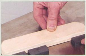
-------- l Use the piece of plywood to line up the magnets on the jointer's
table. Make sure that there are no metal chips caught under the magnets.
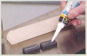
Apply silicone adhesive to the magnets. Epoxy will work, but the bond will
be weaker.
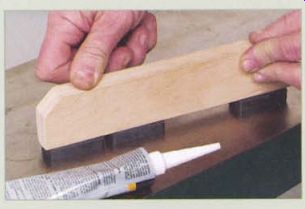
Press the plywood backing into the bead of adhesive. The jig should set overnight
before being moved.
------------------
Fence Alignment
Before reattaching the fence, check it with a straightedge. A small crown or dip over the length of the fence can be tolerated as long as all parts of the fence can be kept vertical to the tables. A twist or wind, to use the woodworking term, creates a problem though, because it will cause the wood to rotate as it passes down the length of the fence. The same solutions for straightening an out-of-flat table apply to a warped fence, with the one additional option of attaching a new wooden face to the casting and either shimming or planing it to a true surface.
Once the fence is remounted on the jointer, square it up and take a test pass with a board that has a good, flat face. Check the resulting edge using a reliable square, being sure to place the stock of the square against the board surface that ran along the fence. Adjust the fence stop as needed to get a square edge on the board.
----------
Remove the Pitch
With disposable knives, always take care to remove all gum and pitch from the knife, the slot, and the knife-locking wedge because clearances are tight on this type of cutterhead.
---------
Setting and Replacing Knives
Each jointer knife must be carefully adjusted so its cutting edge is even with the plane of the outfeed table as the knife passes through the highest point in its arc. When all the knives are set correctly, the freshly cut surface of the board will be supported and guided by the outfeed table, creating a perfectly straight edge.
Adjusting jointer knives can be a frustrating experience. On most home-shop machines, height adjustments are made by moving the knives up or down in slots milled into the cutterhead and then locking them into place. The height of the knife is almost always measured by some tool standing on the outfeed table. The tool can be as simple as a block of wood extending over the cutterhead or as complicated as a dial indicator on a customized stand.
Most methods for setting knife height are fussy and time consuming but still only moderately accurate. Compounding the problem, a knife often will shift out of position as its lock screws are tightened. This section will tell you how to solve both problems. Cleaning up and removing burrs from the knife-lock components will solve the shifting problem; building a simple magnetic jig will make positioning each knife a simple task (see the sidebar on p. 37). On the simplest style of cutterhead, there is no way to adjust the knife position except to nudge the blade up and down, usually with the tip of an awl slipped in behind the knife from the side of the machine, a slow and tedious job at best. With this type of head, a magnetic jig is almost a necessity for changing a set of knives.
Two improvements to the hunt-and-peck approach to knife setting are spring-backed knives and cutterheads with height-adjusting screws behind the knives. Although both methods work, neither is especially easy or foolproof. Spring-backed knives are pushed down into their slots against a pair of small coil springs set into holes in the bottom of the slots. Typically the knife is pushed down by a wood straightedge placed on the outfeed table. Holding the knife against the springs while tightening the lock bolts can be awkward and requires adjusting each end of the knife repeatedly until it is seated properly. A second problem is that the springs pack up with sawdust. They are quite small, and a fumble when removing them for cleaning sends them down the dust chute or into some hidden corner of the jointer's base casting.
On heads with blade-height-adjusting screws, a pair of small stepped blocks, with the adjusting screws threaded into them, ride in grooves behind the knife slot. Turning the Allen-head screws lifts the knife higher in the slot. Exposed to pitch and dust, the adjusters and their grooves must be thoroughly cleaned with every knife change.
Setting knife height with adjusters requires either working with a dial indicator on a stand or bringing the blade up against a straightedge laid on the outfeed table while rocking the head back and forth. Either method of judging the height requires careful attention and repeated checks at either end of the knife while tweaking the adjusting screws.
Using a magnetic jig allows you to remove the springs or height adjusters and avoid the problems they cause. The jointer won't be damaged by removing the parts-they simply slip out of their grooves-and they can always be put back in service later if you change your mind. If you choose to continue using the springs or adjusters, always clean them thoroughly while the knife is out of its slot and follow the setting instructions in the machine's manual.
Some jointers, mostly commercial models, have fixed-position reversible knives that make knife changing a simple job. If your machine has disposable knives, consider yourself lucky and follow the owner's manual for the proper way to set them, since the exact procedure will depend on the model you own.
------ ------
Making a Jig to find Top Dead Center
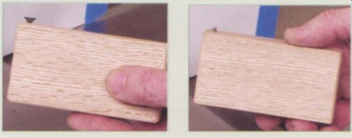
You CAN CONSTRUCT A JIG TO HELP you find top dead center on your machine. The body of the jig is a scrap of hardwood 1.5 in. wide and 4 in. long. For the jig to be accurate, the ends of the block must be square to the sides.
Drill a hole for a 1 1/4-in. drywall screw 3/8 in. from one corner. You should leave the screw head proud approximately 1/8 in. (see the photo at left) . If the tables of the jointer are a very close fit to the cutterhead, the screw head may not fit in the gap between the cutterhead and the table. If so, substitute a finishing nail for the screw (see the photo at right).
----
--------------
FINDING TOP DEAD CENTER
Before replacing the knives, you must locate top dead center (TDC) for the cutterhead. This is the point directly above the centerline of the head.
When a knife's edge is at TDC, it is at the high point of its arc and in the proper position for setting.
To find TDC on your machine, first make a locating tool as explained in the sidebar below. To use the tool, move the fence to the back edge of the table and raise the outfeed table to a point where a straightedge on the outfeed table will just clear the cutterhead with the knives rotated out of the way. When the outfeed table is set, extend the straightedge so it is over the infeed table and bring the infeed table to the same height (see the top photo on p. 40).
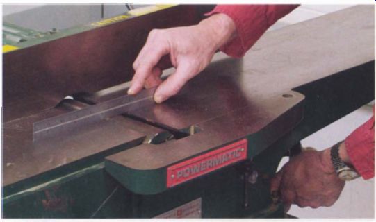
------------ To find top dead center, begin by moving the fence all the
way back and raising both tables to the same height.
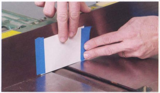
----------- You need to draw several lines to locate TOG. A piece of paper
taped to the fence makes the lines easy to see.
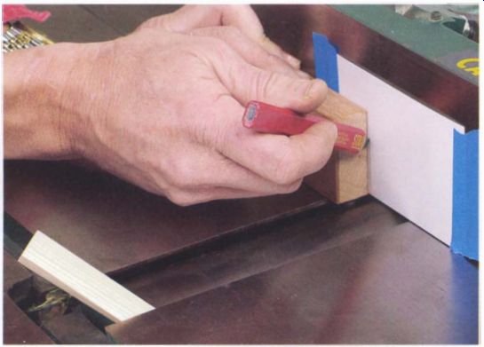
-------------- Slide the pin on the center-locating tool against the cutterhead
and mark the paper where the edge of the block comes to a stop.
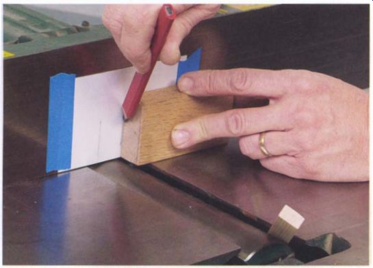
------------- After using the locating tool on one side of the head , flip
it over and make a second mark from the other side.
Next, tape an index card or piece of paper to the fence to create a good surface for marking (see the bottom photo above). Place the locating tool on one of the tables with the screw or pin down in the gap between the table and the cutterhead. Slide the tool toward the head until the projecting screw comes to a stop against the cylindrical surface of the head.
Holding the tool firmly against the table and cutterhead, mark the paper along the edge of the block above the pin (see the top photo on the facing page). Repeat this operation on the other table, again making a mark where the tool stops (see the bottom photo on the facing page). TDC is midway between the two marks. Locate this midpoint with a ruler and, using a square, draw a vertical line on the paper to mark TDC as shown in the top photo below.
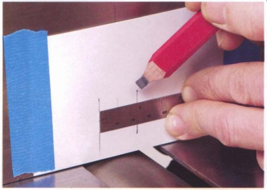
----------- Use a ruler to locate the midpoint between the two lines. This
is top dead center.
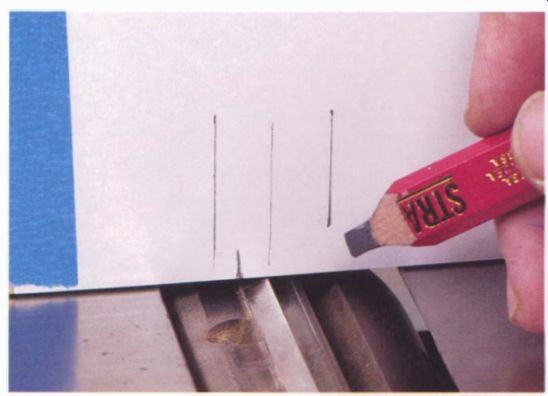
-------- Line up the edge of one of the knives with the TDC line and make
a final mark even with the back of the knife slot. This mark is used to position
the head when the knife has been removed.
Once you have TDC marked on the fence, rotate the cutterhead until the edge of one of the knives lines up with the line marking TDC. With the knife in the TDC position, make a mark on the paper in line with the back edge of the knife slot (see the bottom photo on the facing page). The purpose of this mark is to give you a reference point to position the cutterhead when the knife is removed.
CHANGING KNIVES
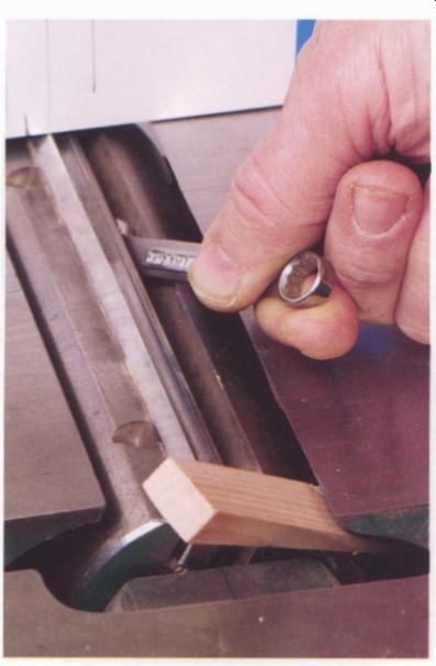
-------- Locking the head with a pine wedge when changing knives makes
it less likely that the wrench will slip.
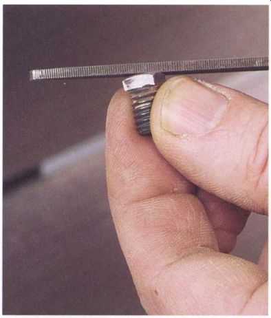
--------- Burred and distorted lock-bolt heads are the primary cause of
shifting when locking the knives in place. Clean each bolt head with a fi
le, removing burrs and giving the bolt head a slightly rounded shape.
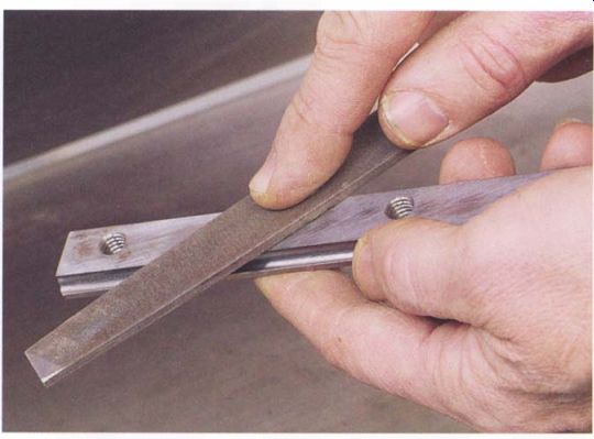
--------- To prevent the knife from shifting as you tighten the lock bolts,
file the face of the lock bar smooth.
To change knives, start by removing one blade and its lock bar from the cutterhead (see the photo below). Most manufacturers recommend that you remove knives one at a time to avoid distorting the cutterhead.
Clean up the knife slot with solvent and a rag to remove any pitch and dirt, using steel wool or Scotch-Brite on the worst spots. Do the same with the locking bar. Next, lightly run a file back and forth a few times against the front and rear faces of the slot to remove any burrs and high spots. When the slot faces are smooth, re-wipe the slot with a clean rag and solvent to remove any filings.
The face of the lock bar that bears against the knife must be flat to prevent the bar from shifting as the screws are tightened. Smooth the face of the bar using a file. If the bar is bent, straighten it out and then file the face of the bar flat (see the bottom photo on the facing page). The locking bolt heads are almost always burred from being repeatedly tightened and loosened. These burrs are the primary reason why a blade will shift as it is tightened. You should smooth and slightly round the bolt heads, making sure the high spot on the bolt head is centered (see the top photo on the facing page). Check that the wrench is a good fit on the flats of the bolt heads, which will limit rounding and burring of the heads in the future. The wrench supplied with the machine may fit poorly, so buying a good-quality mechanic's wrench and filing the bolt heads to fit is well worth the trouble.
To install a new knife, rotate the cutterhead until the back edge of the empty slot lines up with the edge mark on the fence. Lock the head in position by tapping a small softwood wedge into the gap between the head and the infeed table. Drop the knife and lock-bar assembly into the slot and snug up the bolts until the knife is lightly locked in place (see the photo below). Now evenly loosen the bolts just until the knife can move freely.
Place the magnetic knife holders on the outfeed table, one near each end of the knife, being careful not to block wrench access to the locking bolts (see the photo on p. 46). The knife should be pulled up against the underside of the magnets. To check that the knife is free to move, push it down into the slot with a stick against the cutting edge and make sure that it springs back against the magnet as soon as you stop pushing.
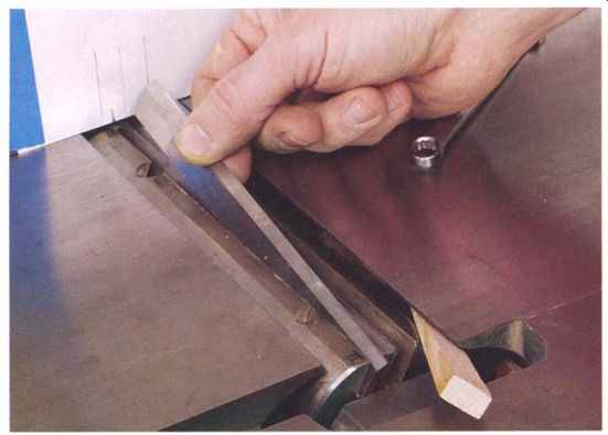
----------- Line up the back of the knife slot with its mark on the paper
and drop in a sharp blade and the lock-bar assembly.
Reducing Bolt Friction -------- Make sure the bolts turn easily when they are threaded into the bar. If not, clean out the threads with a tap. Apply a little wax to the threads and bolt heads to reduce friction as they are tightened. All other surfaces of the bars, knives, and slots should be left dry or with only a very slight oil film.
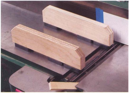
-------- Place the shop made magnetic jigs on the jointer's outfeed table
so the front edges of the jigs are slightly past the edge of the knife.
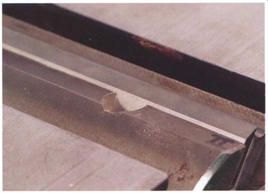
---------------- On most jointers, when the knife height is set correctly,
a narrow strip of the knife back will be visible above the back edge of the
slot.
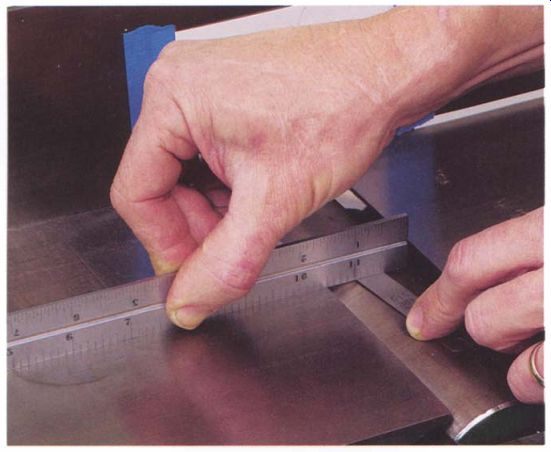
-------------- A second way to set knife height is to raise the outfeed
table until a feeler gauge of the proper thickness fits between the cutterhead
and a straightedge laid on the table.
If you have the machine's manual, it will give you the recommended blade height. But if you lack this information, use either of the methods outlined below and you will probably be close to the proper height. No matter how you set the blade height, always rotate the head by hand after installing new blades to be absolutely sure that nothing interferes with the cutterhead.
To set the blade height when you don't have factory specifications, lower the outfeed table, with the magnetic knife holders still in place, until the back edge of the bevel on the knife drops below the outside surface of the cutterhead, then raise the table until the bevel and about 1/32 in. of the back of the knife projects above the head. On most machines, this is the proper position for the knife (see the top photo on the facing page). If the cutterhead on your machine has the back edge of the slot machined away so that you cannot judge the proper knife setting, set the outfeed table with a straightedge and feeler gauge about 0.015 in. above the cylindrical surface of the head (see the bottom photo on the facing page). Once the outfeed table is properly adjusted, don't move it until you have replaced all of the knives; this will guarantee that they are all cutting in the same arc. If the height adjustment on the table has a lock, use it to hold the setting.
Once you have the knife at the correct height, gently snug up the lock bolts. To reduce the chance of the blade shifting, go back and forth between all the bolts, tightening them progressively in three or four stages.
If the blade does shift, try tightening the bolts in a different sequence or tightening a couple of bolts firmly before the others. One bolt is often the worst offender, so leaving it to last will prevent it from causing mischief.
After you have the first knife installed, use the same procedure to replace the other two.
Testing the Machine
It's time to test the machine. Double-check that you have tightened all the knife-lock screws, reattach the guards, and plug in the jointer. Before turning on the machine, always remove all tools from the table; vibration can cause tools to walk across the table, possibly into the cutterhead.
To set the outfeed table height, choose a test board about 2 ft. long. Lower the outfeed table to slightly below where it was set for installing the knives, then set the infeed table for a 1/16-in. cut. Start the jointer and take a pass on the edge of the board. Because the outfeed table is slightly low, the board will have an obvious snipe in its trailing end (see the top photo on the facing page). Raise the outfeed table in small steps and take additional passes until the snipe just disappears; this should be the proper height for the outfeed table.
To test the jointer for making straight edges, carefully pick two clear pine boards about 4 ft. long and from 4 in. to 6 in. wide. These boards should have no twist, and you should joint their wide face flat if necessary.
On each board, the best face should run against the fence. Mark the opposite face with a V as shown in the bottom photo on the facing page, then pass both boards through the machine with the V facing out and pointing down toward the table.
Start with the board firmly on the infeed table. As soon as 8 in. to 9 in. of the board are over the outfeed table, apply most of the down pressure there with your left hand positioned just past the cutterhead. Keep your left hand in place and do all the feeding with your right hand, keeping pressure down and against the fence with your left hand as the board passes over the cutter.
Next, place the two boards edge to edge with the V's facing out and toward each other (see the top photo on p. 50). The fit should be very good. If the boards are high in the center, slightly lower the outfeed table, but if the boards are low in the center, raise the outfeed table. Be sure to adjust the table in very small increments, checking after each adjustment.
Once you get an airtight joint, the table shouldn't need to be readjusted until the next time you change the blades. If the outfeed table has a lock screw for the gibs, you should tighten it to hold the setting.
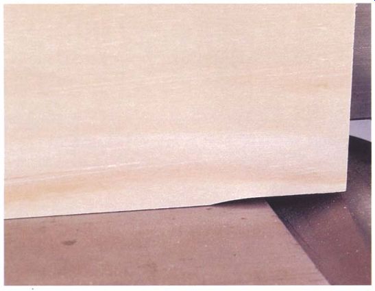
--------- To fine-tune the height of the outfeed table, start by taking
test cuts with the table deliberately low. The setting will create an obvious
snipe in the board's trailing edge.
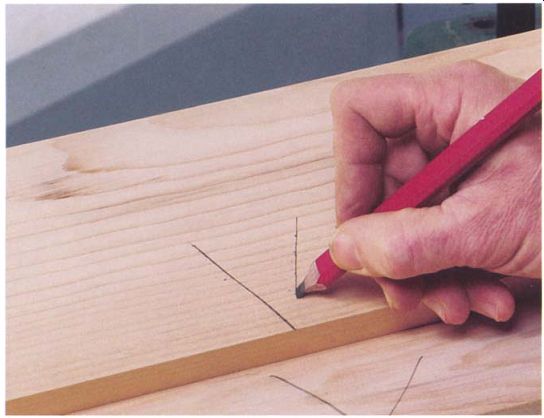
-------- Mark each of a pair of test boards with a V to indicate which
side will face out and which edge will be against the table when making a
test cut.
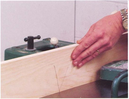
-------- With the V properly oriented, joint the edges of both boards,
taking care to keep the cut edge firmly against the outfeed table through
the entire cut.
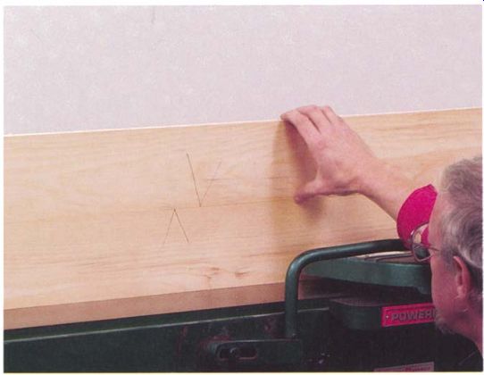
----------- Stand the test boards together edge to edge with the V's pointing
at each other. If the joint isn't perfect, a slight adjustment of the outfeed
table will correct the fit.
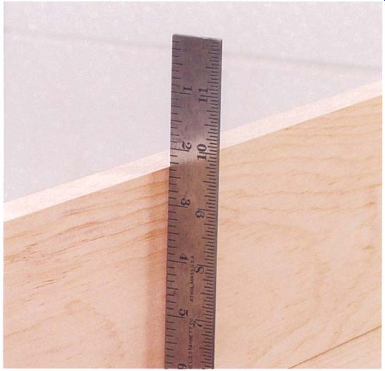
------------ Placing a straightedge across the joint will show whether
the fence is square to the table. Readjust the fence stops if needed , and
run the test boards again to check the setting.
Once you are cutting straight, place a straightedge across the joint.
If the fence isn't quite square to the table, there will be a slight bow or crown. Fine-tuning the fence's vertical stop will eliminate the problem (see the photo above). The last step is to set the depth of cut scale for the infeed table. Place a short straightedge on the outfeed table and extend it over the infeed table, then raise the infeed table until it just touches the straightedge.
Now position the pointer for the depth scale to read zero and the jointer is ready to use.
Prev. | Next | Article Index | Home