Accurate joinery is only possible when both faces of a board are flat and parallel to each other. A jointer can flatten the face of a board, but only a thickness planer can make both faces parallel and the stock even in thickness. A thickness planer, along with a jointer, is essential for transforming roughs awn planks into stock ready to be made into furniture.
Until fairly recently, thickness planers were the heavyweights of the woodworking shop. A machine capable of planing a board 20 in. wide might easily weigh half of a ton; even small machines weighed several hundred pounds. In the 1970s, lighter and less expensive planers became available and rapidly gained popularity in both large and small cabinet shops. These bench top machines are now made by a number of manufacturers.
Anatomy
The operating principle of a thickness planer is simple. The planer's cutter head is locked at a fixed height over a table. With one side already planed flat, a board passed under the cutter is reduced to a uniform thickness.
The cutting head on the smallest machines holds just two knives, whereas most large machines have three or four. Some large industrial machines have a series of short, staggered knives that function like a spiral cutter. Whatever type of blade the machine has, it will work properly only when the blades are sharp and precisely aligned.
---------------

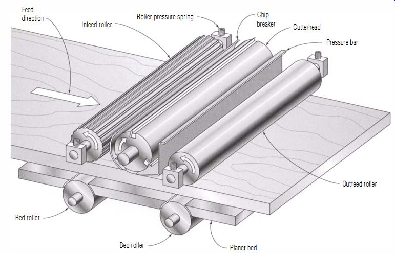
The Thickness Planer -------- Stock already flattened on one side is driven under the cutterhead by the infeed roller, planed, and then pushed out of the machine by the outfeed roller. For good results, the components must be precisely aligned.
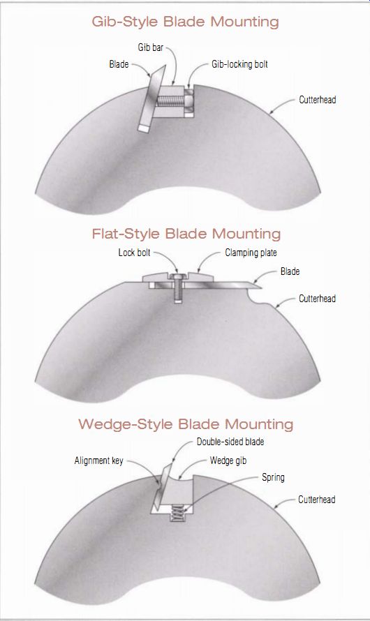
--------------- Gib-Style Blade Mounting; Flat-Style Blade Mounting ;
Wedge-Style Blade Mounting
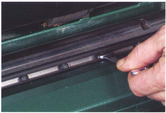
-------- Common gib screws are awkward to tighten because the small bolt
heads are difficult to reach.
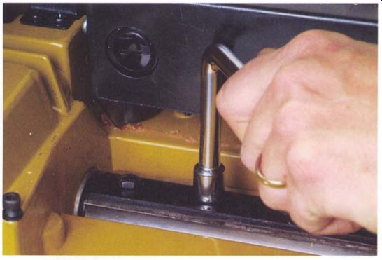
---------- Generally seen only on smaller machines, flat-mount knives
are easy to set and tighten.
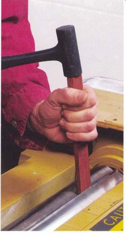
------------- Wedge-lock knives are easy to change. Wedges are tapped back
against small springs to release the knives, then with new blades in place,
the wedges pop back as soon as the machine is turned on.
ATTACHING KNIVES TO THE HEAD
There are three general approaches manufacturers have taken to holding and adjusting knives in the cutterhead: a preset alignment typical of disposable blades, spring-backed knives set with a simple jig, and jackscrew adjusted knives that are often set with a dial indicator supplied by the manufacturer. All three methods work well, although the preset disposables are, of course, the quickest to change and are virtually foolproof in their alignment.
There also are several ways of locking the knives into the head. On older and larger machines, a gib bar securing the blade is locked into a groove in the head by bolts spaced a couple of inches apart. These tend to be fussy to adjust. The lock bolts can be awkward to reach, and the blade will often creep out of position as the bolts are tightened (see the top photo on p. 91). Portable machines often use a flat mount that clamps the blade under a broad plate. This type of blade attachment is easy; the bolts are large and easy to reach and the blade won't shift as the bolts are tightened (see the bottom left photo on the facing page). Gib and flat-mount arrangements are used for both disposable and standard blades.
A third method, which is good only for disposable knives, uses wedges set by centrifugal force to hold knives in place (a well-known brand of this type is TERSA). Wedged knifes are the simplest and fastest to change, but this system is typically available only on larger commercial machines (see the photo at right). The only small planer I know of that uses this approach is the Inca jointer/planer, a combination machine designed for a small shop.
Disposable knives are standard on many portable planers and are available as an option on heavier industrial machines. Most disposable knives are a thin strip of high-speed steel sharpened on both edges. A lengthwise groove or holes for alignment pins precisely position the blade in the planer's cutterhead. Disposable blades are often more economical than standard blades when setup time, resharpening cost, and quality of the cut are factored in.
---------------------
Resharpening Disposables
Some disposable knives are designed with enough extra metal in the blade to allow them to be re-sharpened two or three times before being retired. If you attempt this, remember that the grinding must be very precise to keep the blades matched to each other in width.
-------------
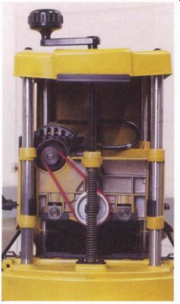
------------ The head of this portable planer rides on four posts, adjusted
by the crank on top of the machine.
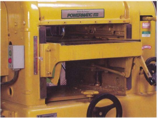
------------ On large planers, the table moves up and down to adjust for
stock thickness.
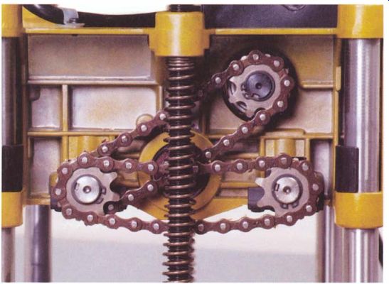
------------- Portable planers achieve a low-speed drive through a gear
box attached directly to the motor. Only the final chain drive will need service.
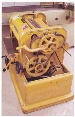
------------- Standard V-belts connect the motor to the cutterhead
on this large machine. Belts also step down the speed for the drive rollers,
but the final low-speed drive is chain driven.
KEEPING STOCK MOVING AND CHIP FREE
All planers use feed rollers on both the infeed and outfeed sides of the machine. Large planers have corrugated steel rollers for extra traction on the infeed side and non-marring steel feed rollers on the outfeed side.
Portable machines use rubber-covered rollers on both sides of the cutter head. To reduce friction between the table and the stock, most large machines have a pair of unpowered bed rollers set in the table directly below the feed rollers.
To prevent tearout, large planers have a chip breaker that rides on the stock on the infeed side of the cutterhead. By bearing down on the wood a fraction of an inch away from the knives, the breaker forces the chips raised by the knives to break off instead of running along the grain and tearing chunks from the surface. Portable planers don't have chip breakers.
Instead, they rely on higher cutterhead speed, limited depth of cut, and a slow feed rate to limit tearout.
Large machines also have a pressure bar on the outfeed side that holds the board tightly against the table. By preventing the end of the board from rising, the pressure bar minimizes snipe, the small but annoying divot Standard V-belts connect the motor to the cutterhead on this large machine. Belts also step down the speed for the drive rollers, but the final low-speed drive is chain driven.
------------------
Check the Stock
Not all sniping is due to faults in the machine. Poorly prepared stock also can cause the problem.
When the back of the board-the side that goes against the table-isn't flat, or when a board has a lengthwise bow in it, sniping may result.
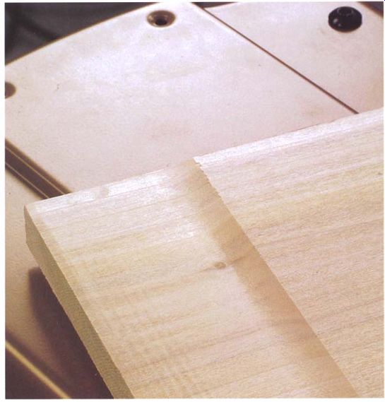
----------- Sniping leaves a small step on one or both ends of a board.
It can be reduced or eliminated by changes in procedure and careful tuning
of the planer.
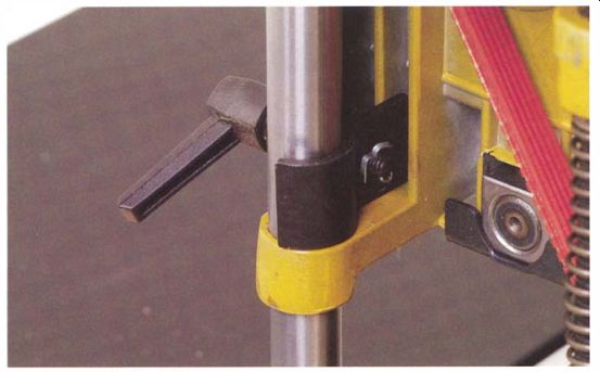
------ Locks holding the planer head in position during a cut can reduce
sniping.
Troubleshooting
Thickness planers typically misbehave in one of three ways: snipe at one or both ends of the board, difficulty in feeding the stock, or a poor finish on the planed surface.
SNIPE
A snipe is a slightly deeper cut in the leading and trailing few inches of a board (see the photo below). In most situations, the cause is simple: The stock lifts off the planer's table, allowing the knives to cut too deeply.
When both feed rollers are pressing down on the board, it can't lift, so sniping occurs near the ends of the board when only one roller is applying pressure. Large planers have chip breakers and pressure bars close to the cutterhead to further limit lifting of the stock. Adjusting those parts is critical to preventing snipe.
Snipe can result when the long end of the stock is not supported. The weight of a long board can easily lever its leading or trailing end off the table, causing a deeper cut. As the first and last portions of the stock are being fed, the opposite end of the board should be held level with or slightly higher than the planer's table. Using infeed and outfeed tables or roller stands is a good solution. The problem occurs more often on portable planers.
If your machine has bed rollers, they should be set at least a few thousandths of an inch above the table's surface. If the bed rollers are low, the pressure of the feed roller can flex the board downward into the bed-roller slots, causing the board's ends to curl upward slightly and creating sniped ends. If the bed rollers are set too high, you can get a reverse snipe, where the first or last few inches of the board will have a slightly higher step.
Some portable planers, however, have a design flaw that can cause sniping. As the leading edge of the stock begins to pass under the outfeed roller, the power head can flex slightly upward due to the added pressure.
This lifts the cutting head and causes a step in the board's surface. When the trailing end of the board clears the infeed roller, the opposite motion occurs. The head drops when the pressure is off the roller, sniping the trailing end of the board. To prevent this, many second-generation machines were designed to be stiffer and had head- locking mechanisms added to eliminate movement of the head once the height was set (see the photo above). If your portable machine doesn't have a head lock, a certain amount of snipe may be inevitable, especially if wear has loosened its fit on the guideposts. If the machine has a locking mechanism, make sure it is working properly. In large machines, where the table moves instead of the power head, a similar problem can occur if the table's gibs are loose, allowing the table to rock as the stock is fed.
STOCK WON'T FEED SMOOTHLY
There can be many reasons why a board won't feed smoothly through the planer. But before looking for a complex mechanical problem, it always pays to check the condition of the rollers and table. Dirt and pitch on these parts is usually the cause.
The table surface should be as friction free as possible. A good first step is to wipe down the table with solvent on a rag. Use a scrub pad if necessary to remove heavy buildups on cast-iron tables, but avoid the use of abrasive pads on the chrome-plated tables of portable planers because the finish can be damaged. If the table is rusted, polish it with emery paper and oil and follow up with wax or a coating of TopCote, a lubricant made for the job. If you use a spray, be careful to keep it off the feed rollers so they don't get slippery.
If the planer has bed rollers, make sure they're clean and revolve freely. A bent roller will cause the stock to advance erratically. If a roller is higher on one end than the other, the stock will skew sideways as it is fed.
While you are cleaning the table, it pays to clean the feed rollers too, even though they're awkward to reach. Use a solvent and rags, going over the rollers a couple of times to make sure they are free of dust or oil that might make them slip. If the rollers are rubber covered, take a close look at them. You should be able to press the tip of your thumbnail into the rubber easily. If the rubber is glazed and no longer resilient, the roller will have trouble gripping the stock and should be replaced.
While working under the cutterhead, check the bearing surfaces of the chip breaker and pressure bar, if your machine has them. They should be clean and free of burrs. You can also wax them, but be careful to keep wax off the nearby rollers. Rollers that are set too high or too low will cause feeding problems, as can misaligned chip breakers and pressure bars. To set these components, see "Tuning Up the Cutterhead" on p. 103.
Dull knives also can lead to feeding problems. If knives are dragging rather than cutting cleanly, the rollers will slip trying to force the stock under the cutterhead. Try feeding narrow stock at the far left or right edge of the table where the knives are probably sharper. If the slippage disappears, the center sections of the knives are likely dull.
Occasionally the drive line will cause trouble if a V-belt is slipping or a pulley or chain-drive sprocket is loose. If the stock isn't feeding, glance under the head (from the side of the machine for safety) while the power is on. If the feed rollers aren't turning, the problem is in the drive line.
-------------------
Unplug the Machine
Always remember to unplug the machine. You don't want it to go on accidentally while you are sticking your hands into its innards to service the rollers or check the bed. And while you're in there, avoid accidental contact with the knives.
-------------------
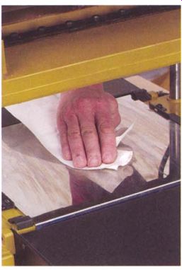
---------- Pitch buildup on the planer's table is the most common cause
of feed problems. To prevent the problem, clean and wax the table occasionally.
-------- Making a Base for a DIAL INDICATOR ------
To SUPPORT THE DIAL INDICATOR DURING a tune-up of your thickness planer, you should construct a small base for it. The one shown below is made from MDF, but you could also use plywood or hardwood.
The indicator is attached to the base with a 1/4-in.-dia. bolt and a wing nut. If your planer does not have bed rollers, the 1/2-in. hole in the bottom piece of the base won't be needed.
The upright part of the base is attached to the bottom with two drywall screws, which should be countersunk. The base stands on three legs, which are ordinary flathead sheet-metal screws, 3/8 in. long, that protrude about J4 in. (see the bottom photo). The legs prevent dust or wood chips from being caught beneath the unit, which would cause a measurement error.
If your planer has bed rollers, the legs have another advantage. They allow you to adjust the dial indicator up or down so it can be zeroed out on the plane bed with the zero at the 12 o'clock position. Although this isn't absolutely necessary, it makes the dial easier to read and may help to prevent errors. Once the indicator is set this way, you can measure and adjust the height of the rollers more easily.
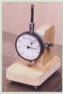
--------- Mounting a dial indicator on this shop-made base makes it easy
to measure and adjust the height of the planer's feed rollers, pressure bar,
and cutterhead.
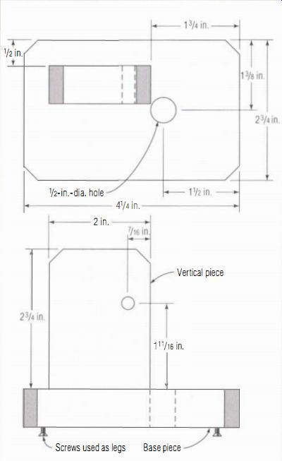
----------- The dial indicator used to set up and tune a thickness planer
should be mounted on a base made from a flat, smooth material, such as MDF.
---------------------
ROUGH FINISH SURFACE
In addition to causing feeding problems, dull knives create burned and glazed areas on the surface of the stock that will lead to problems when gluing and finishing. The next time you install new knives, plane and set aside a few sample boards in both hardwoods and softwoods. Later, when the knives have become duller, you'll have a reference to judge the degradation of surface quality. Under a magnifying glass, the difference can be dramatic.
A knick in the knives will leave a raised line down the length of the board. If the knives are otherwise usable, loosening and resetting one knife a fraction of an inch sideways will eliminate the ridge. If one knife is set higher than the others, the stock will have a pronounced ripple in its surface. This effect is most noticeable at high feed rates. A cutterhead with a high knife will also sound different; the high knife will make a slightly louder snicking sound that is distinctive once you've learned to recognize it.
A planer can make a lot of chips in a hurry, and if they aren't cleared away they can wind up getting caught between the spinning knives and the surface of the board. Chips caught under the blades cause numerous small dings in the surface, which is more pronounced in softwoods or when taking a heavy cut (see the photo at left). On portable planers, this problem often occurs when an accessory dust hood has been attached but is not hooked up to a dust collector. The added restriction of the hood blocks the smooth flow of chips. If the problem occurs on a planer that does have dust collection, check the system for a clog or restriction that is cutting the airflow.
-----------------
Diagnosing Knife Problems
The surface left by dull knives will be rough, with torn fibers and crushed pores. Sharp knives leave cleanly trimmed fibers and open pores.
Once you can recognize the difference, a quick check with a magnifying glass will give you a fast, reliable measure of the condition of your planer blades.
Another clue to dull knives is in the sound of the stock being planed: Dull knives make considerably more noise than sharp blades.
---------------

-------- When chips are not removed quickly enough, they can get caught
under the knives, leading to these characteristic dings in the planed face
of the board.
Setup and Maintenance
Large cast- iron planers meant to stand directly on the floor don't require much in the way of setup beyond being leveled and supported evenly on all four corners. Generally, they do not need to be bolted down.
Because planers generate a huge amount of chips, they should be located close to a central dust collector with as few restricting bends in the ductwork as possible.
You should bolt portable planers on a stand for stability and to bring them up to a practical height. The table should be about 24 in. off the floor (see the photo on the facing page). When possible, hook up a portable planer to a 4-in.-dia. dust-collection hose. If you are using a 2),-j-in. shop vacuum for chip removal, keep the hose short and eliminate any tight bends. If you aren't going to use any dust pickup on a portable machine, leave off the accessory dust-collection hood.
Large planers use a V-belt drive off the motor that should be checked occasionally for looseness and wear (see the photo at left on p. 100). Portable planers use a short, cogged belt to drive the cutterhead. This type of belt typically has a very long life and should not need tightening.
If you have a large machine with a gear box, you should drain and replace its oil occasionally, once a year for frequently used machines. The small gear boxes on portable planers are sealed and don't require oil changes. If you don't have a service manual that specifies oil types, 80W-90 gear oil meant for car transmissions should work well. Without a manual, knowing how much oil to put in the gear housing can also be a problem.
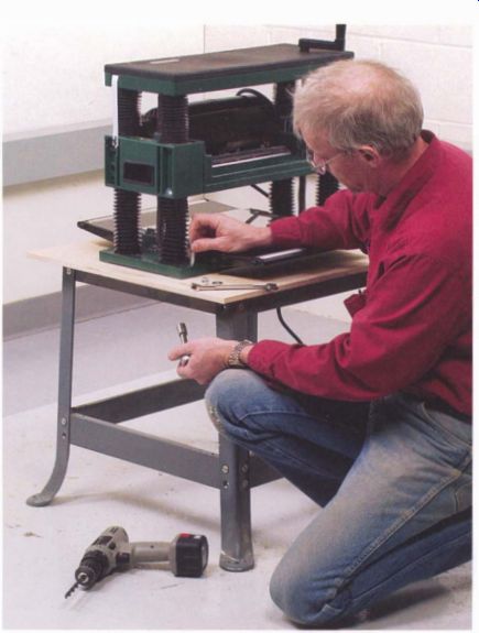
----------- For safety and convenience, portable planers should be mounted
on a stand roughly 24 in. high.
If the oil is filled through a plug in its side, the gear box is usually filled until the oil reaches the bottom edge of the filler hole. If the box is filled through a top-mounted plug, you should not fill it all the way to the top; look for a cast-in oil-level mark on the outside of the box. If there is no mark, leave the oil an inch or so below the inside edge of the filler hole.
On most planers, the feed rollers are powered by a chain drive, which you should clean and re-oil occasionally. A spray penetrating oil and some rags do a good job of removing the old grease and accumulated sawdust.
Use a heavy oil to lubricate the chain, or use a spray lube designed for chain drives.
------------
Fire Risk
There is a small but serious risk of fire when you regularly run a planer with an inadequate chip-removal system. If the system gets overloaded and clogs completely, chips can become packed around the spinning cutter and catch fire from friction. Once the chips start burning, they'll be fanned by the air that the dust collector manages to pull through the clog. The burning chips may get pulled into the pipes, spreading the fire into other parts of the system and the dust collector itself.
Almost all of the following information on tuning up a planer applies to full-sized cast- iron machines, which have many components to adjust. If you own a portable planer, you'll have considerably less to do. The sections on adjusting the chip breaker and pressure bar won't apply, for example, because these small machines don't have them. Nor will the sections on adjusting roller heights and pressures; although portable machines have these parts, they can't be adjusted.
---------------
--------------
Oil with the Machine Off
As tempting as it may be, do not run the machine while cleaning and oiling the chain. A mistake can lead to mangled fingers.
---------------
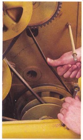
---------- When properly tightened, a belt should flex only a fraction
of an inch under firm finger pressure.
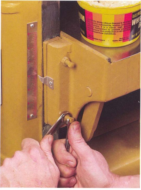
----------- Be sure to clean and lube the table slides on planers before
adjusting the gibs.
Table Adjustments
Thickness planers whose heads or tables move up or down on posts-and this includes almost all portable planers-generally don't have a way of adjusting how tightly the head or table assembly fits on the posts. These machines often make up for any play in the fit with a locking mechanism.
A small number of machines, however, have gibs or split bushings that can be adjusted. In this case, tighten them to remove any play but leave them just loose enough to slide smoothly. If the machine has a mechanism for locking the head or table on the posts, make sure it locks solidly. The locking mechanism should have some adjustment for tightening the fit.
In large planers, the table typically runs up and down on rectangular cast- iron ways machined into the side castings. You can adjust the gib screws to eliminate any play between the moving component and the supports while allowing the table to slide smoothly (see the photo at right on the facing page).
CHECKING FLATNESS
Two surfaces in a thickness planer must be flat for the machine to work properly. The first is the table that the stock rides on. If the table is bowed or twisted, the stock won't feed smoothly and the finished board will be uneven in thickness. The second critical surface is the edge of the pressure bar. If the bar doesn't bear down evenly, the leading and trailing ends of the board can lift off the table and cause snipe. Part of the tune-up will deal with adjusting the pressure bar, but it can't be properly adjusted if it isn't straight and smooth to start with.
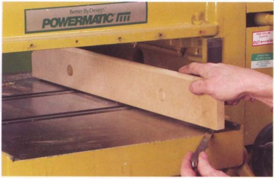
------------- If the planer's table isn't flat, boards will be uneven
in thickness. Ideally, the table will vary no more than 0.005 in. anywhere
along the straightedge.
Check the table for flatness using either a reliable straightedge or a test bar made up according to the instructions on pp. 26-3 1. Check across the length, the width, and both diagonals of the table. If your machine has bed rollers that interfere with the straightedge, you may be able to remove them. In some machines, the rollers can be set so they are below the surface of the table. If not, use three identical pieces of shim stock to lift the straightedge over the rollers. If the table is out of flat, use feeler gauges to measure the error.
For most work, an out-of-flat measurement of 0.005 in. over 12 in. is tolerable. Beyond that, you're probably going to have joinery problems later as you use the wood. If a cast- iron table is out of flat, you will either need to replace it or remachine it to correct the problem. On portable planers, you can fix an out-of-flat table by layering aluminum-foil shims between the base casting and the sheet-metal working surface of the table.
To check the pressure bar, you will need a reliable straightedge, which doesn't need to be as long as the bar. By sliding a 12-in. straightedge back and forth, you can reliably check a 16-in. or 18-in. bar. Begin by running your fingers down the length of the bar, being careful of the knives in the nearby cutterhead. (The power should be locked out whenever you're working on the machine.) As you run your fingers along the bar, feel for burrs and low spots, then use the straightedge to check the bar for overall straightness. A light shining from behind the bar will show any gaps between the bar and the straightedge. If the bar isn't smooth and straight, with the gaps less than 0.002 in., remove it from the machine and use a file to straighten its bearing edge and round its leading edge to a smooth profile.
EXTENSION TABLES
On portable machines, the extension wings should line up with the table under the cutterhead. The inner edges of the wings, where they are attached to the machine, should be even with or slightly below the height of the main table. If the wings are high, they will cause sniping and jamming problems. But there typically is no height adjustment here; if the alignment is off, you will have to change or modify the wing's pivot bolts.
The height of the outer end of each wing is adjusted by bolts mounted in the planer's frame near the wing's pivots. To adjust the wings, raise the power head to its highest position and place a builder's level through the machine and across both tables. Apply moderate down pressure on the level and adjust the bolts on each wing to give the wing a slight up-tilt (see the photo on the facing page). When the wings are properly adjusted, the level will be parallel to the main table and raised about 1/32 in. off the surface. Move the level from one side of the machine to the other, adjusting the two bolts aligning each wing until the level clears the table evenly all the way across. A slight upward tilt compensates for any downward flexing of the wing caused by the weight of the board. In addition, it forces the leading and trailing edges of the board tightly against the table, reducing snipe.
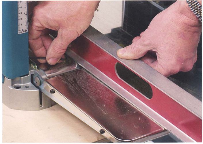
-------------- Fold-down tables on a portable planer should be adjusted
to have a small up-tilt on their outer edges to compensate for their flexibility.
--------------------
Use Your Own Tools
Wrenches supplied with power tools are often of poor quality.
They typically are made of soft steel and machined to loose tolerances.
Replacing the factory-supplied tools with good-quality mechanic's wrenches will often eliminate the repeated burring and rounding off of lock-bolt heads.
---------------
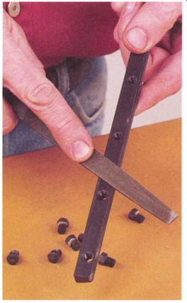
---------------- To clamp the knives in place without shifting, the clamp
bars must be smooth and straight and the lock bolts must be burr free.
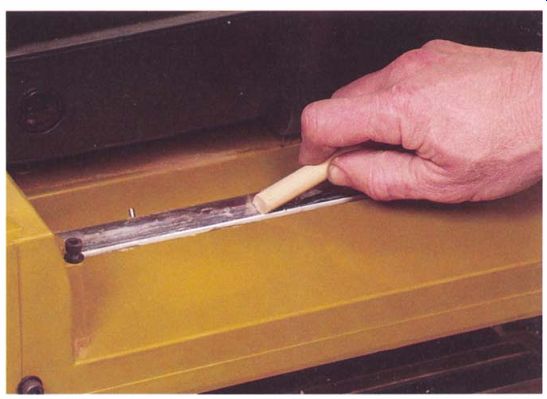
------------ Before replacing a blade, always clean the slot or flat the
blade mounts in. A dowel cleans the rounded profile of this chip-breaker groove
effectively.
Tuning Up the Cutterhead
Knives must be installed in a planer's cutterhead precisely. If one knife is higher than the others, it will dull rapidly and a planed surface will be rippled. To work their best, knives should be set evenly, with height varying by no more than 0.001 in. across their width and from blade to blade. You should clean and lubricate the knife-adjustment and locking components before installing new blades.
Begin tuning up the head by removing one knife and all its associated parts. To prevent distorting slotted-style cutterheads, you should remove and replace knives one blade at a time, locking in each new blade before moving on to the next one.
If you do need to remove all of the knives at once, gradually loosen the lock bolts of the knives in progressive steps, and reinstall the knives in the same way, gradually tightening all of the bolts as you work your way around the head several times. When removing all of the knives in the head at once, also remove the lift springs or jackscrews. Otherwise, they will drop out when you rotate the head to bring another knife to the top position. To keep track of parts and which blades have already been changed, use a marker to number each knife location on the head before unbolting anything.
Once you've removed the knife, use a solvent with scrub pads and scrapers to remove any accumulated pitch on the head. If the head is badly gummed up with pine pitch, use turpentine, which is an effective solvent.
You can clean out round-bottomed chip-breaker grooves by using the end of an appropriately sized dowel as a scraper (see the photo above). A powered or hand-held wire brush is fine for cleaning up steel parts, but don't wire-brush aluminum because aluminum is too soft.
To remove burrs, lightly pass a file over the machined faces of the flats or grooves in the head. The surfaces of the clamping plates or the lock bars that bear against the knife blade should be smooth and flat. True them up using a file or by lapping them on sandpaper on a flat surface (see the photo at left). The wrench flats on the lock-bolt heads should be flat and square, so clean up any rounded and burred heads using a file. Check that a wrench will slip onto all of the bolt heads in any orientation, and file down the bolt heads to fit snugly on just one size wrench. If the original wrench doesn't fit well, try a different one.
On slotted heads, the lock-bar bolt heads bear against the side of the knife groove to wedge the knife in place. Bolt heads should have a slight crown or conical point centered on the axis so they can be tightened without shifting the knife out of position. If a bolt head is burred, flat, or off-center, reshape it with a file or stone. If the bolt head needs extensive reshaping, keep it symmetrical by chucking it in a spinning drill while filing.
Polish the screw heads using fine emery paper so they will turn as friction free as possible against the side of the groove. Be sure to thoroughly wash off all the grit left behind by the polishing. If the debris gets onto other parts, it will cause binding and rapid wear.
Next, check that the bolts thread easily into the bars or the head itself. Burred threads on bolts can be cleaned up using a small triangular file; internal threads will need a tap to clear them. To aid in tightening, the threads of all bolts should always be lubricated with a small amount of grease during final assembly. Use a rag dampened with penetrating oil to wipe down the knives and the lock bars or clamping plates as you install them, leaving a very slight film of oil. The oil will reduce pitch buildup and enable the parts to move smoothly during adjustment.
Springs or jackscrew components that fit down into the head behind the blades should slide smoothly in their sockets and the screws should turn easily. Springs especially can get misshapen and bind. Always check, clean up, and lightly lubricate these parts before you install new knives.
Occasionally, parts in the head may need to be replaced. For safety and to preserve the balance of the head, always try to get replacement parts from the machine's maker. If you can't get original equipment parts, use high-strength bolts, normally called grade 8, and replace them and the springs in opposing pairs or full sets to keep the head in balance.
----------------
Maximum Blade Life
Check that your sharpening service is grinding away only the minimum amount of metal needed to restore the edge on your blades. If your service is removing more steel than necessary, you're going to be forced to buy replacement blades more often. I've noticed that some grinding shops are definitely more heavy-handed than others.
------------------
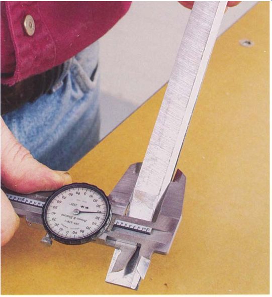
------------ You should check re-sharpened blades for uniform width, straightness,
and burrs before installing them.
Sharpening and Installing Blades
In addition to being sharp, planer knives must be perfectly straight and even in width. Many disposable blades can be lightly re-sharpened one or more times, but they must be carefully ground to keep the set perfectly matched in width because their height can't be adjusted.
Since a precision grinder is an expensive tool that requires a fair amount of practice and skill to run, small and mid-sized woodworking shops often find it more economical to have a professional blade sharpening service do the work or to use disposable blades. Small, low-speed wet grinders, typically with horizontal wheels, are sometimes advertised as being capable of grinding planer blades, but their performance is marginal at best. On these low-end machines, the carriage guiding the blade wobbles and flexes far too much to maintain the accuracy required for long planer blades.
Before installing a set of knives sharpened by an outside service, inspect them carefully. First, sight down each blade's length to make sure the blades aren't bent. Next, place the sharpened edge against your best straightedge and hold it up to the light. There should be no gaps, especially at the ends where a poorly sharpened blade will often be rounded inward. Visually, the ground surface of the bevel should be consistent from one end of the blade to the other. Once again, most problems show up near the ends.
Using calipers, measure the width at the middle and at both ends of each blade. The width should be the same down the full length of the blade. To maintain the balance of the cutterhead, all of the blades in the set should be within a few of hundredths of an inch of each other in width. To line up properly when installed, reground disposable blades should be within a thousandth of an inch of each other in width.
The blades should be burr free. If they aren't, clean them up with a very fine stone, being careful not to round over the edge. The blades should not be discolored-that indicates that they were overheated when they were sharpened. A blade that has lost its temper won't hold an edge.
CHANGING PLANER KNIVES
Because there are many different jigs and methods of adjustment and locking for planer knives, it isn't possible to offer instructions that apply universally to all machines. The information in this section will guide you through the process in some detail, but you also should refer to the instruction manual that came with your machine for step-by-step procedures and the proper amount of knife exposure.
If you haven't done so already, read through the previous section on setting up the cutterhead. Knife changes will go faster and be more accurate if you take the time to make sure the cutterhead's lock and adjustment components are working properly.
TIGHTENING LOCK BOLTS
I'm covering this topic first because it is the one step in installing blades that is common to all machines. The best procedure for tightening blade
lock bolts, once the blade height is set, is to start by snugging up the bolts closest to the ends of each blade. Next, gently tighten the center bolts and, finally, the intermediate ones, alternating between the bolts on the left and right sides of the blade.
Once the bolts are all snug, go back and progressively tighten them using the same pattern in two or three steps. Using this procedure will usually eliminate the tendency of blades to shift out of line as they're locked in place. If a knife does shift, the problem is most often due to rough, poorly lubricated bearing surfaces on the bolt heads or warped lock bars or clamp plates.
INSTALLING ADJUSTABLE KNIVES
For adjustable knives, install a new blade, lightly snug up all of its lock bolts, and back the bolts off a quarter to half a turn. With the bolts backed off, the knife should move freely. Retighten the two bolts nearest the ends of the knife, then very slightly loosen these two bolts so the knife is again able to move but with just the barest amount of free play. By minimizing the free play, height adjustments will be more accurate and less prone to shift when locked down.
When adjusting knife height, work only on correctly setting the height of the ends of the blade; as long as the blade is straight, the middle will automatically be at the proper height.
--------------
Don't Overtighten
Many people overtighten the lock bolts because they worry that a knife might fly off. But repeatedly overstressing the lock bolts will reduce their strength, which can lead to failure, creating the very situation they seek to avoid. The bolts should be firmly tightened, of course, but not so much that the wrench is damaging the bolt heads or the bolts are nearly impossible to back off at the next blade change.
----------------
Removing Chips
Chips can be hard to remove from a magnet, so try using the sticky side of a piece of masking tape.
--------------
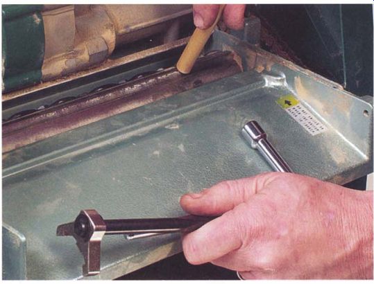
----------- Before tightening spring-backed blades, check that they're
moving freely. Press the blade with a length of dowel and make sure it springs
back against the jig.
INSTALLING SPRING-BACKED BLADES
Spring-backed blades are set using a jig supplied with the machine. The better jigs are double-ended, contacting both ends of the blade at once close to the outermost locking bolts. A variation on the spring-backed blade is a head without springs that depends on a magnet in the jig to lift the blade and hold it at the proper height. Magnetic jigs are a bit fussier to work with because the blades can easily be jarred loose before they're tightened.
For accuracy, always check that the contact points of the jig are free of sawdust or pitch that would throw off the height setting. Magnetic jigs are often thrown off by metal chips clinging to the magnet's face. To eliminate these chips, position the jig on the cutterhead and then lift it back off and check the faces of the magnets. This procedure will catch any steel chips that were down in the machine or clinging to the new blades.
To install knives with a double-ended jig, place a knife in its slot and press it back into position with the jig, being sure to locate the jig over the knife as the instruction manual indicates. To check that the knife is seating properly, press it a bit farther back into its slot using a short dowel to protect your fingers, then watch to see that the blade freely springs back against the jig when the pressure is released (see the photo above). When you're satisfied that the knife is positioned properly, snug up the two end bolts to hold the blade in place, then remove the jig and progressively tighten the remaining bolts.
Some planers come with a jig that positions only one end of the knife at a time. Using this type of jig is slower and more prone to error since moving the blade against the jig at one end also slightly shifts the opposite end. You will be forced to go back and forth several times, loosening, resetting, and then tightening the ends with smaller and smaller adjustments until both ends of the blade are at the correct height.
To minimize the degree of shifting and speed up the process when using a jig that sets one end of the blade at a time, always place the jig as close as possible to the outermost lock bolt as you set each end of the knife. Often, you can convert a simple jig into one that will set the blade height at both ends by purchasing a second jig from the machine's manufacturer and attaching the two jigs together with a dowel handle that's about three-quarters of the blade length.
INSTALLING JACKSCREW-SET KNIVES
On some planers, the blade height is adjusted by jackscrews that lift the blade into position and is checked using a dial indicator mounted in a base supplied with the machine. The basic procedure is simple. To begin, zero the indicator against the outer surface of the head on the rounded area between two of the knives (see the photo below). Be careful to make sure all of the contact points are free of dust. Once the indicator is zeroed, carefully set it aside where it won't be jarred and lose its setting.
Place a new knife in its slot and adjust the lock bolts to leave the knife with a small amount of free play. Place the indicator, which was zeroed against the head, over the knife, close to one of the jackscrews (see the photo on p. 110), then shift the indicator so it reads the high point of the edge. The knife should be below the height specified in the manual. If not, back off the adjusting screws and tap the blade down to seat it in the notches of the jackscrew's housing. Next, set the two lock screws nearest the jacks to exert a slight drag on the knife while allowing it to move upward as you adjust the jackscrews. The slight drag improves accuracy by eliminating free play of the knife in the slot and by keeping the back of the knife snug against the jackscrews.
Using a jackscrew, raise one end of the knife to a point a few thousandths of an inch below the specified height. Move the indicator and repeat this procedure at the opposite end of the knife, raising the knife to just below the specified height.
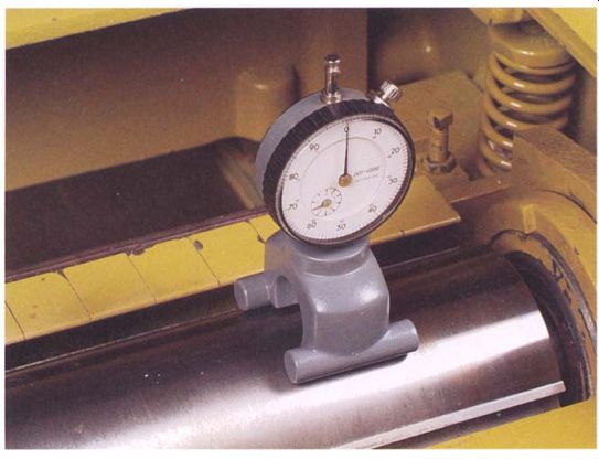
----------- The first step in setting knife height is to zero the indicator
against the cutterhead between knives.
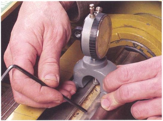
------------ Using the jackscrews, adjust the knife height while measuring
the blade's exposure with the indicator.
If the machine's manual is missing and you don't have a blade-height specification, bring the knife up until the full width of the bevel on the back edge is exposed and note the indicator's reading. Now add a couple of thousandths of an inch to the reading and use this number as the indicator reading to set all of the knives in the head. If you have to set the blade height using this method, for safety always turn the cutterhead through one complete revolution by hand to be absolutely sure the knives won't strike some part of the housing.
Once both ends of the knife are just shy of full height, repeat the process a second time to take the blade up to its exact height. Be careful not to overshoot the mark. If you do go over, back off the jackscrews slightly, tap the blade down, and try again. You should reach the final setting while raising the blade out of the slot with the jackscrews, never while tapping the knife to lower it. Once you've set the correct height, gradually tighten the lock screws following the procedure outlined earlier in this section.
Installing disposable knives
After checking blade-locking components, install disposable knives following the instructions that came with the machine. In most cases, there is little that can go wrong. Just make sure the knife and its mounting surfaces are clean, flat, and burr free. The thin blades can be easily distorted and may be prevented from seating and aligning properly.
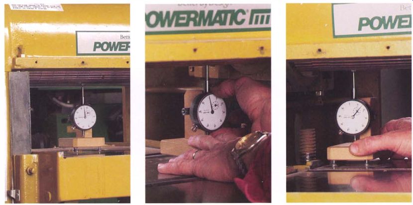
------------- To check cutterhead alignment, start by adjusting the table
to bring the indicator's hand to the vertical position after it has made a
couple of turns.
Move the indicator to one side of the cutterhead and adjust it so it reads zero.
Move the indicator to the opposite end of the cutterhead and take another reading.
Here the head is out of parallel by 0.005 in.
Aligning the Table with the Cutterhead
To plane a board to an even thickness, the cutterhead must be parallel to the surface of the table. It's easy to check this with a dial indicator on a simple base. If the table and head aren't parallel, correcting the alignment is relatively simple, although the exact procedure will depend on the design of the planer.
To check for parallel, make the indicator base described in the sidebar on p. 97, and attach the indicator with its stem pointing upward. A large, flat tip will work better than a small one. Lower the table to clear the indicator assembly, and rotate the cutterhead until a smooth portion of the head, midway between two knives, is facing the table. Place the indicator in the middle of the table under the approximate center of the cutterhead, and adjust the table height to make contact between the tip and the rounded surface of the head.
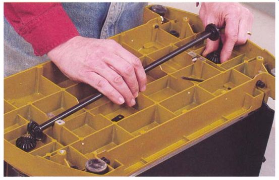
--------- On most portable planers, there is a geared shaft or chain drive
connecting the left- and right-side jackscrews. Unhooking the linkage allows
you to raise one side of the head to make it parallel with the table.
Continue to move the table to rotate the indicator's hand a couple of turns. Slide the indicator from front to back to locate the lowest point of the head, then with the indicator positioned, raise or lower the table slightly to bring the indicator's hand to the 12 o'clock position and lock the table or head in place (see the photo at left above). Now place the indicator under one side of the head, moving it from front to back to locate the low point and zero the dial (see the center photo). Move the indicator to the opposite side of the table, position it under the lowest point on the head, and take a reading. If the dial doesn't still read zero, the cutterhead and the table aren't parallel (see the photo at right on p. Ill) . Correcting an out-of-parallel table is simple, at least in theory. You turn the jackscrews, or the nuts they go into, on just one side of the table to bring it into line. If you have the owner's manual, it may tell you how to make the adjustment. If you don't have specific information, start by looking under the table or the power head, depending on which moves, to see if there is a threaded bushing that the jackscrew goes into. If you can see a bushing that is hex shaped or has holes around its perimeter for a bar to turn it, loosen the bushing's clamps or set screws and turn the bushing to align the table and cutterhead.
If you can't find a bushing to adjust, temporarily disconnect the chain, gear drive, or cogged belt that connects the left- and right-side jackscrews, and turn one of the screws to realign the table (see the photo above). If you have a machine with four jackscrews, turn both of the screws on one side equally to adjust the alignment. After making an adjustment, recheck with the dial indicator, then lock up the set screws or reconnect the gear train.
-----------------
One Last Check
As a final check for parallel, you can rotate the head to place a knife at the bottom dead center position and measure between the table and the knife for equal dimensions on the left and right sides of the table. If the knife isn't parallel to the table, double-check that the blade is properly installed before making any adjustments to the jackscrews.
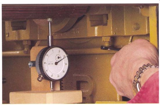
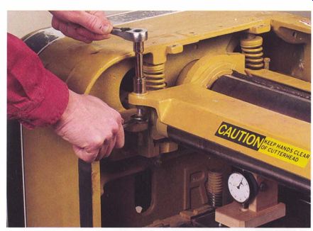
--------- Set infeed and outfeed roller height by adjusting screws at
each end of the rollers after taking a measurement with a dial indicator.
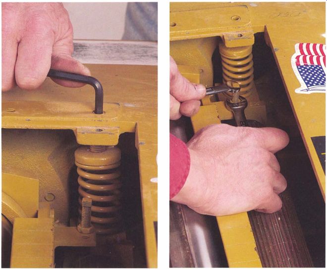
----------- On some planers, the spring pressure on the feed rollers can
be adjusted. Stock that feeds poorly or skews in the machine is a sign the
adjustment may be necessary.
---------Using the indicator and its base, set the height of the chip breaker so it is slightly lower than the arc of the knives.
-------------------
Segmented Rollers
Taking a reading against a segmented infeed roller can be difficult. Segments float on springs, and they are not concentric with the inner shaft that drives them. Try disconnecting the roller's drive chain so the roller rotates freely, then tap the segment you want to read until it runs nearly concentrically. Using the dial indicator, find the segment's high and low points, which will be 180 degrees apart. Midway between these two points, you can get an accurate reading of the roller's height. Once you've located and marked these midpoints on segments on either end of the roller, you can set its height.
Infeed and Outfeed Roller Adjustments
Roller heights are set relative to the knives in the cutterhead, so the knives should be sharp and properly adjusted before making any adjustments to the rollers.
Begin adjusting the infeed roller by manually turning the cutterhead until one of its blades is at the bottom of its arc over the table. Set up the dial indicator on its base with a wide, flat tip on the plunger. Place the indicator under the middle of the cutterhead, and raise the table until the indicator's tip is touching the blade and the hand has made a couple of turns. Gently rock the cutterhead back and forth and shift the indicator's base until you are sure the blade is at the lowest point of its arc and the indicator is centered directly below it. With the head properly positioned, raise or lower the table slightly to bring the indicator's hand up to the 12 o'clock position. If the height-adjustment mechanism has a lock, set it now. Finally, zero the indicator and note the value on the tenths dial.
With the indicator zeroed, slide it underneath the left end of the infeed roller. If the roller is corrugated, rotate it to place a raised segment facing down toward the table. Take a reading, checking that you are still in the same tenths range. The infeed roller should be set slightly closer to the table than the arc of the knives on the cutterhead. If you don't have specifications, try setting the infeed roller 0.030 in. closer than the knives for a solid roller and 0.060 in. closer for a segmented roller. Once the roller height is properly set, the hand of the indicator will rotate one-third to a little more than one-half of a revolution clockwise when you move from under the knives to under the roller.
Setting roller height is easy on most planers. An adjustment bolt with a locknut is located under the roller's bearing housings at either end of the roller (see the photo above). To reset the height, loosen the bolt and thread it in or out until you have the reading you want on the dial indicator, then tighten the locknut.
The outfeed roller is also set closer to the table than the cutterhead; if you don't have specifications, set it 0.030 in. closer than the knives. The procedure for checking and setting the height of the outfeed roller is identical to the method just outlined for setting infeed roller height.
SETTING ROLLER-SPRING PRESSURE
The infeed and outfeed rollers are pressed tightly against the board being planed by springs above the bearing housings at the ends of each roller.
Spring pressure is generally not adjusted on a routine tune-up. On many machines, the springs can't be adjusted.
On planers that do allow you to adjust spring pressure, the setting would only be changed if there are feeding problems and all other possible causes have been eliminated. Typically, most feed problems are caused by excess friction between the table and the board, dull knives, or the stock binding against the chip breaker or pressure bar. However, there are some situations where spring pressure should be adjusted. If stock consistently skews when the leading end of the board first passes under the infeed roller (and the bed roller is set correctly), increase the pressure on the side that isn't pulling as well (see the photo at left on the facing page). On some machines the tension on the end of the roller driven by the chain drive needs to be slightly increased to compensate for torque and pull of the chain.
If the rollers slip excessively and there are no friction or binding problems, increase the spring pressure at both ends of the roller. In time, springs can weaken, and it may be necessary to replace the springs if tightening them doesn't correct slippage.
If the feed roller is corrugated and you primarily run softer woods, such as pine and poplar, you can decrease spring pressure on the infeed roller so the roller is less likely to leave an imprint on the stock.
CHIP-BREAKER ADJUSTMENT
Like the rollers, the chip breaker extends slightly below the arc of the knives. If you don't have a specific setting from a service manual for your machine, set the bar 0.030 in. below the level of the knives. On some planers, the chip breaker rides up and down with the infeed roller assembly, so the breaker should be adjusted only after the infeed roller height has been set. For the same reason, the chip breaker's height should be checked after any adjustments are made to the infeed roller height.
In setting the chip breaker, follow the same procedure used to set the roller heights. That is, use a dial indicator zeroed on a blade in the cutterhead (see the photo at right on the facing page). Depending on the design of your machine, the two adjusting bolts, one at each end of the breaker assembly, can be reached from either above or below the head assembly.
PRESSURE-BAR ADJUSTMENT
The pressure bar holds the stock down as it leaves the cutterhead. If the bar is set too high, the planer will snipe the ends of the board. Unlike the chip breaker and feed rollers, the pressure bar is not spring-loaded; it won't ride up to clear the stock if it is set too low. To prevent jamming, it must be set precisely, ideally no more than 0.001 in. to 0.002 in. higher than the arc of the knives.
Use the same procedure you followed for setting the chip breaker and feed rollers. Zero the indicator on the knives at bottom dead center, then take a reading with the indicator under the bar. To set the pressure bar accurately, adjust its position immediately after you have installed new knives in the machine. Set the height 0.002 in. higher than the knives (see the top photo on p. 116).
--------- The height of the pressure bar on the outfeed side of the planer
is critical to good planing.
Set too high, it will allow sniping; too low, jamming.
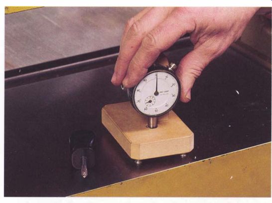
-------- To check the height of bed rollers, mount the indicator on its
base pointing downward, and zero the dial against the table's surface.
BED-ROLLER ADJUSTMENT
To reduce friction that might stall a board, large planers have unpowered rollers recessed into the bed directly under the infeed and outfeed rollers.
Properly set, they stand a few thousandths of an inch above the level of the table. Some planers have control levers that allow you to adjust the bed roller's height to obtain the smoothest feed for the type of wood being planed. On machines with fixed-height bed rollers that can only be adjusted by undoing bolts and locknuts, you may have to experiment to find the best height for stock you typically plane.
Use the same procedure for adjusting both the infeed and outfeed bed rollers, which should be adjusted to the same height. Begin by attaching the dial indicator to its base with the indicator's plunger projecting downward through the X-in. hole in the base, being sure to use a flat, wide tip on the end of the plunger. Set the base on a flat surface and adjust the three leveling screws by approximately equal amounts to bring the indicator's hand up to the 12 o'clock position after the hand has made a couple of revolutions from its unloaded position (see the bottom photo on the facing page). Move the indicator and base onto the planer's table, and zero the dial with the tip bearing against the table. Next, place the indicator over the end of the infeed bed roller, moving the base from front to back to position it over the highest point on the roller's surface. Rotate the roller through one complete revolution while keeping an eye on the indicator.
The hand should show a variation of no more than a couple of thousandths of an inch. If the variation is greater and it is not caused by a burr or pitch on the roller's surface, then the roller is out of round, bent, or has a bad bearing.
Repeat this check over the other end of the roller and at its center.
If you measure the greatest variation at the roller's midpoint, the roller has probably been bent. You'll need to replace or repair a wobbly roller because it would cause feeding problems, usually in the form of an intermittent binding every few inches as the board is fed through the machine.
If the roller is running true, check that the indicator is still zeroed when its tip is on the table's surface. If the roller's height is adjusted by a lever, set the control to the zero or lowest position. Place the indicator back over one end of the roller, centering it over the high point, then take a reading and check the other end of the roller.
On a lever-adjusted roller, the roller, at its lowest setting, should project above the table by 0.006 in. to 0.008 in. at each end and the two measurements should be the same. On fixed-height rollers, try a beginning height of around 0.010 in. for planing hardwoods and 0.015 in. for softwoods. The best height can only be determined by experiment. You want the minimum height needed for smooth feeding because any additional projection of the rollers can cause binding against the pressure bar and possibly a reverse snipe, in which there is a higher step on the trailing end of the stock.
The height of each end of the roller is typically adjusted by a screw and locknut reached from underneath the table. On some planers, the bed-roller bearing housings are eccentric and the roller height is set by loosening a set screw and rotating the housing in the planer's frame. Lever-adjusted rollers can have either a screw-and-nut arrangement or the linkage may need to be uncoupled so that each end of the roller can be moved independently with its jackscrew.
After setting the infeed bed roller, repeat the same procedure for the outfeed bed roller, setting it to the same height as the infeed side and even in height at both ends.
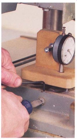
----------- The bed-roller bearings on this planer are mounted slightly
off center in their housings. Roller height is adjusted by rotating the housings.
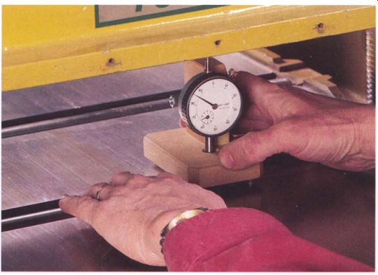
------------ When used on the bed rollers, the indicator can check initially
for a bent roller or worn bearings.
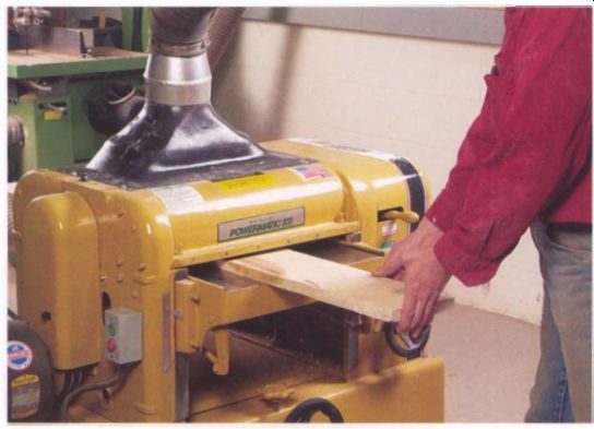
-------- The final step in tuning a planer is to run a test board. Once
the machine is tuned, it should hold its settings for a long time.
RUNNING A TEST BOARD
Once you've cleaned up the planer, installed new knives, and adjusted everything, it's time to run a test board (see the photo on the facing page). This is primarily to check the pressure-bar setting. As explained in "Troubleshooting" on p. 94, poorly prepared stock or feeding the board improperly can cause sniping that is not the fault of the machine.
To test, feed the board while taking a light cut and watch for jamming under the pressure bar. If the stock jams, raise the bar a few thousandths of an inch at a time until the jamming stops. The more likely case is the board will have snipe on either end and the pressure bar can be dropped a few thousandths--as long as it doesn't lead to jamming. To prevent jamming later, you may have to accept a tiny amount of snipe, 0.001 in., with new knives. It will disappear as the knives wear in.
Finally, check the thickness of the planed board on the long edges. If the board consistently reads thicker on one edge than the other, check and readjust the table-to-head alignment. Once the machine is planing well, just keep it clean and well lubricated and its knives sharp. A full tune-up shouldn't be needed again for a long time.
-------------------
Test Boards
YOU should use pine as a test board if you work primarily with softwoods or a straight-grained hardwood. The board should be knot free, of fairly even thickness, and have one face jointed flat. Sight down the board to make sure it isn't twisted, cupped, or bowed.
--------------------
Prev. | Next | Article Index | Home