AMAZON multi-meters discounts AMAZON oscilloscope discounts
When electricity is conducted through a wire, the movement of the electric energy heats the wire. The heat is generated by the resistance of the wire to the flow of electric current through it.
It follows, therefore, that the greater the flow of cur rent through a wire, the greater the resistance to it and the greater the heat generated. The flow of electric cur rent is measured in amperes, so the point to remember is that the higher the amperage of the welding circuit the greater the heat developed in the arc.
AMAZON multi-meters discounts AMAZON oscilloscope discounts
It might help to fix this point in mind if you compare the flow of electricity through a wire to the flow of water through a pipe. The rate of flow of water through a pipe is expressed in gallons per minute. The rate of flow of electricity through a wire is expressed in amperes. And since the flow of electricity determines the amount of heat developed, the greater the amperage, the greater the heat in the arc.
It should also be remembered that some metals have much less resistance to electricity than others, so these metals generate less heat than others under identical conditions. Such metals as copper and aluminum, For example, have a low resistance to electricity, therefore are excellent conductors. If copper and aluminum are large enough in cross-section for the current carried they won’t heat up to any noticeable degree.
On the other hand, metals that are poor conductors or that are not large enough for the current carried, will get very hot and may even melt.
Industry has been using this heating-due-to-electrical-resistance principle for a long time, in many ways.
Electric Fuses
The best-known application of this principle is probably that of electric fuses.
A fuse is intended to be the weakest point in a circuit. A small piece of metal which is the conductor within the fuse, is designed to carry only a limited amount of current. If more than this amount of current goes through the fuse, the metal gets hot and melts. This breaks the circuit.
Crucible Steels
Another application of this principle is the melting method usually used for producing high-quality special steels ( ill. 8).
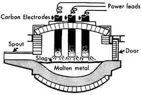
ill. 8—The heating-due-to-electrical-resistance principle as applied in producing
crucible steel. The crucible is connected to one terminal of a high-amperage
source of power, one or more carbon electrodes are connected to the other terminal.
A vessel to hold the metal, usually called a crucible, is connected to one terminal of a high-amperage source of power. An electrode, usually carbon, is connected to the other terminal of the source of power. The metal to be melted is placed in the crucible and the electrode is brought into contact with the metals, thus completing the circuit. The resistance to the flow of current through the metal generates enough heat to melt it.
The Welding Circuit
To create a welding circuit you must have a source of electric power—the welding machine, known simply as the “welder.” Two cables are used—one connects the electrode holder to one terminal of the welder and is called the electrode cable, the other connects the ground clamp to the other terminal and is called the ground cable ( ill. 9).

ill. 9—The welding circuit consists of welding ma chine, welding cables,
ground clamp and electrode holder. The ground clamp may be connected to the
work table or directly to the work piece.
Both cables should be of a size, length and material that will carry the required current with little resistance; otherwise power will be wasted in the form of heat in the cable.
The important part of the welding circuit is at the work. The electricity coming from the power source goes through the electrode cable via the electrode holder to the electrode. The welder controls the flow of electricity and the arc circuit by controlling the position of the electrode. He causes the electricity to flow by touching the tip of the electrode to the work and creating an arc. He stops the flow of electricity by moving the tip of the electrode away from the work and breaking the circuit.
If the welder closes the circuit by touching the electrode to the work and holds it in direct contact there, the electrode will soon become red hot. The resistance to the flow of electricity through the electrode, which is small in cross-section and a poor conductor, causes this heating. With the electrode held against the work- piece, enough heat will usually be generated to fuse the two together (and sometimes to fuse the electrode to the electrode holder as well).
If the work piece is thin and light, it too will become very hot, because its small size will offer resistance to the flow of current.
The Electric Arc
Dry air is a poor conductor of electricity. It can al most be classified as a non-conductor. Electricity really doesn’t flow through air. But under certain conditions it will jump across an air gap in an arc. The welding current flowing through this high resistance air gap generates the intense arc heat which may be from 6000 F to 10,000 F. As a result, the base metal melts at the point where the arc touches the work and the electrode melts (and becomes filler metal) at the point where the arc touches the tip of the electrode.
To keep the arc stable and consistent, certain chemicals are put into the electrode coatings to help contain and direct the arc and also to protect the molten filler metal from the air while it transfers across the arc.
The point to understand here is that the resistance across an electric arc creates the heat which a welder uses to melt metal. The welding machine or power source can be adjusted to deliver the right amount and the right type of power to the end of the electrode. The welding operator must direct the arc to the right spot on the work, must hold the arc at the right length and must move it at the right rate of speed to get the desired result.
Welding Machines
Two basic types of machines are used as sources of welding power. One type provides alternating current, commonly referred to as A.C. The other type provides direct current, commonly referred to as D.C.
Direct current flows steadily and constantly in one direction. Alternating current alternates or reverses its direction of flow -- usually at the rate of 60 times a second. Accordingly most A.C. welding equipment is 60 cycle.
A D.C. circuit is said to have a positive pole and a negative pole. The terminals of the circuit, that's , the cable connections at the machine, are marked + (Positive) and - (Negative).
By making the proper cable connections, D.C. current can be made to flow through the welding circuit in either of two ways:
(1) From the work through the arc to the electrode holder. This is called “straight” polarity.
(2) From the electrode holder through the arc to the work. This is called “reverse” polarity.
It’s easy to remember this difference if it’s noted that in straight polarity welding the current returns to the machine through the electrode—that is, the electrode cable is connected to the straight line (—) negative pole. All you have to remember is: straight polarity.
With some welding machines you don’t have to change the cable connections to change polarity— you can do so by simply turning a switch.
Straight or reverse polarity connections are not a factor with A.C. welders because the current flow is continually reversing itself. The current changes direction 120 times a second with A.C. welding current. The polarity of the electrode therefore changes 120 times a second.
Most A.C. welders are power transformers which take the incoming 220 or 440 volt utility power and transform it to low voltage, high amperage welding cur rent. By the addition of a rectifier to a transformer welder the output current can be changed from A.C. to D.C. Some A.C.-D.C. rectifier-transformers supply both A.C. and D.C. current for welding.
D.C. power is usually supplied by a direct-current electric generator that's driven by either an A.C. motor or a gasoline or other internal combustion type engine. When the generator is driven by an internal combustion engine, we have complete independence from primary electric power and we can weld out in the field, on pipe lines or any type of construction work, far from electric lines.
Prev: What is Welding
Next: Safe Practices