AMAZON multi-meters discounts AMAZON oscilloscope discounts
In order to set the stage for our readers we would like to define some basic terms used in this guide.
Machines are man-made concrete systems consisting of a totality of orderly arranged and functionally connected elements. A system is characterized by having a boundary to its environment. The system's connection to its environment is maintained by input and output parameters. Each system can usually be subdivided into two or more subsystems. Generally, these subdivisions may be made with a varying degree of detail depending on our overall purpose. Consider , for example, the "clutch coupling" system shown in Fig. 1. We would usually find this "system" as an assembly within a machine. However, if we wanted to investigate the system from a functional point of view, we could dissect it into the subsystems "elastic coupling" and "clutch." These subsystems, in turn, could be broken down into system components or individual parts.
For the purpose of reliability assessments we have found the following definitions useful.
System and Mission
A system is any composite of hardware or software items that work together to perform a mission or a set of related missions. A mission is the external "goal" of a system. A function in turn is the internal "purpose" of a system or system components needed to accomplish the mission.
A complex system may be made up of two or more groupings of hardware or software items, each of which has a distinct role in performing the mission of the system. The definition of function and mission in a given case is frequently subject to personal interpretation but should be as thorough as possible. Consider , for example, the oil system of an oil-injected rotary screw compressor ( Fig. 2). Cursory examination may lead to the definition of the system mission or function as "Supplying oil for lubrication and cooling to the compressor." A better idea would be to subdivide this "function" into at least four related but distinct sub-functions and subsystems:
Sub-functions:
1. Oil admission when compressor is running
2. Oil cooling and temperature control
3. Oil filtering
4. Air/oil separation
Subsystems:
1. Oil system - oil stop valve, item 28
2. Oil system/water system - coolers
3. Oil system - filters
4. Oil/air system – separators
This more thorough breakdown will lead to a better understanding of the system mission as well as its function. The example also reveals that there are several functions that are performed simultaneously by one system, sub system, or their components. It stands to reason that one would want to determine primary and secondary functions in these cases and rank them according to their criticality values.
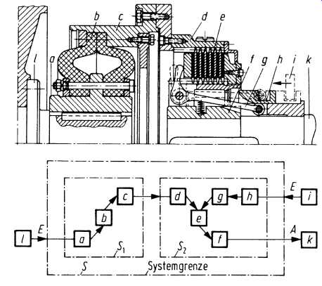
Fig. 1. System "coupling." a-h are system elements, i-l are
connecting elements, S is the total system, S1 the subsystem "elastomeric
coupling," S2 the subsystem "clutch," E inputs, A outputs.
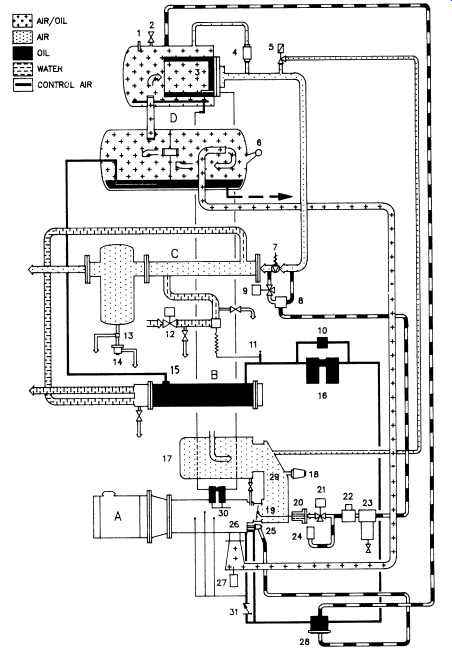
Fig. 2. System diagram of a two-stage oil-flooded screw compressor
(Demag).
Assembly and Part
An assembly is any functional component that can be disassembled into two or more subordinate components without disrupting permanent physical bonds. A simple example of a mechanical seal assembly drawing is shown in Fig. 3. The components of an assembly may be any combination of subassemblies or parts. A part in turn is defined as any hardware item that cannot be disassembled into subordinate components without severing permanent physical bonds. We have already seen how an assembly can be investigated regarding its functional characteristics.
It’s important in machinery reliability assessment to consider the geo metric aspects of machinery parts. We introduce the term "element" to define four internal functions used in machinery assemblies. There are four types of elements:
1. Transmitting elements, such as gear-tooth surfaces.
2. Constraining, confining, and containing elements, such as bearings or seals.
3. Fixing elements, such as threaded fasteners.
4. Elements that have no direct functions but which are inevitably needed to support the above functions (e.g., gear wheels or bearing supports).
The term "component" is used almost interchangeably with "assembly." However, "component" will have a somewhat more independent or stand-alone character. Machinery components , for example, are clutches, couplings, drive belts, gear boxes, or pneumatic and hydraulic systems.
=====
Product Flush (Impeller End) Metal Bellows Tungsten Carbide Kalrez "O"-Rings TFE Wedge Hook Sleeve (Standard) All Metal Parts Stainless Steel 316 Nylon Pin Used For Installation Pumping Ring Intel From Pressure Reservoir Outlet to Pressure Reservoir
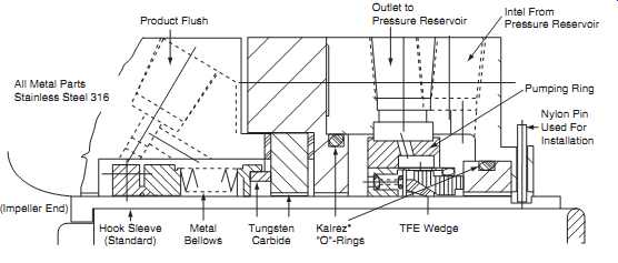
Fig. 3. Mechanical shaft seal assembly (EG&G Sealol).
=====
Assembly Hierarchy
From the foregoing it can easily be understood that machinery systems have a hierarchical structure (see TBL. 1). Assembly hierarchy describes the organization of system hardware elements into assembly levels. Assembly levels descend from the top - or system level - on the basis of functional and sometimes static relationships (see also Fig. 4).
Thorough reliability assessments are carried out in reverse hierarchic sequence: first, we take a look at the lowest-level components; then the components of the next-highest level are assessed, and so on until the top level (the system level) has been reached.
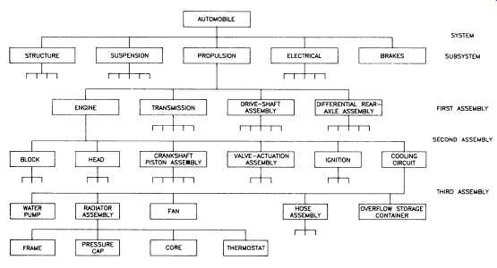
Fig. 4. Assembly hierarchy for an automotive engine cooling circuit.
======
TBL. 1
Assembly hierarchy
System level Example
System Screw compressor package, Subsystem Compressor or driver Assembly Gear assembly Part See parts list Element Gear tooth, bearing, bolt
===
Failure
Machinery systems are subject to failure. In its simplest form, failure can be defined as any change in a machinery part or component which causes it to be unable to perform its intended function or mission satisfactorily. A popular yardstick for measuring failure experience of machinery parts, assemblies, components, or systems is to determine a failure rate.
Failure rate is obtained by dividing the number of failures experienced on a number of homogeneous items, also called "population," within a time period, by the population. For example, if we had 10 injection pumps, and 3 failed during a period of 12 months, our failure rate ___ would be:
_ = 3 failures 10 machine-year
= 0_3 failures machine-year or
_ = 0_3 365×24
= 0_000034 or _34×10-6
_ failures per machine-hour
For reliability assessments, failures are frequently classified as either chargeable or non-chargeable. A chargeable failure , for example, would be a failure that can be attributed to a defect in design or manufacture. A non-chargeable failure would be a failure caused by expo sure of the part to operational, environmental, or structural stresses beyond the limits specified for the design. Other non-chargeable failures are those attributable to operator error or improper handling or maintenance.
Other terms used in the context of machinery failure experience are "malfunction" and "fault" that should, when used, be clearly defined.
Failure Mode
A failure mode is the appearance, manner, or form in which a machinery component failure manifests itself. It should not be confused with the failure cause, as the former is the effect and the latter the cause of the failure event.
Failure modes can be defined for all levels of the system and the assembly hierarchy. For example, deterioration of the oil stop valve ( Fig. 2, item 28) of the oil-injected compressor system could have one of the following failure modes:
1. Fail open. Consequence: The compressor is flooded and cannot be started.
2. Fail close. Consequence: The compressor will shutdown due to high discharge temperature.
3. Fail not fully open or fully closed. Consequence: Gradual deterioration of system performance.
The causes of these failure modes could either be common, such as dirt or foreign objects in the valve, or specific to each failure mode - a broken return spring would keep the valve open, insufficient discharge pressure would keep it closed, and so forth.
Service Life
Service life designates the time-span during which a product can be expected to operate safely and meet specified performance standards, when maintained in accordance with the manufacturer's instructions and not subjected to environmental or operational stresses beyond specified limits [6]. The service life for a given machinery part represents a prediction that no less than a certain proportion of the machinery system or its components will operate successfully for the stated time period, number of cycles, or distance traveled. Service life is clearly a probabilistic term subject to a confidence limit. A good example is anti-friction bearings.
Since a bearing failure generally results in the failure of the machine in which it’s installed, bearing manufacturers have made a considerable effort to identify the factors that are responsible for bearing failures.
A typical equation for determining ball bearing service life shows the rated life to be inversely proportional to the rotational speed of the inner ring and the third power of the applied radial load. Rated life in this case is the so-called L10 life, which is the number of bearing revolutions, or the number of working hours at a certain rotational speed and load, which will be reached or exceeded by 90% of all bearings.
Reliability
Reliability, finally, in general terms, is the ability of a system or components thereof to perform a required function under stated conditions for a stated period of time. It’s also apparent that "reliability" is frequently used as a characteristic denoting a probability of success or success ratio [7]. This means that it may be stated that:
1. A component or piece of machinery should operate successfully for X hours on Y% of occasions on which it’s required to operate; or
2. A machine should not fail more frequently than X times in Y running hours; or
3. The mean life of a population of similar components or machinery should be equal to or greater than Y hours with a standard deviation of S hours.
Maintainability
Many machinery components are designed to receive some form of attention during their life. The goal is to compensate for the effects of wear or to allow for the replacement of consumable or sacrificial elements. The ease with which this kind of work can be done is termed "maintainability." The operational and organizational function of this work is called "maintenance." Maintenance possibilities are illustrated in Fig. 5. It has been shown that, if maintenance on process machinery has to be performed at all, predictive maintenance is the most cost-effective mode.
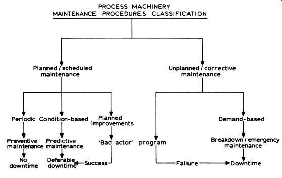
Fig. 5. Process machinery maintenance procedures classification.
Maintainability then is the ability of an item, under stated conditions of use, to be retained in, or restored to, a state in which it can per form its required functions, when maintenance is performed under stated conditions and using prescribed procedures and resources.
Maintainability has a direct influence on the reliability of machinery systems. We will see that maintainability parameters must be considered an integral part of the machinery reliability assessment effort.
Surveillability
Surveillability is closely related to maintainability and will receive the same attention within the overall reliability assessment activity. We have already stated that process machinery maintenance can be optimized by practicing condition-based or predictive maintenance. Surveillability is the key. It’s defined as a quantitative parameter that includes:
• accessibility for surveillance;
• operability if required;
• ability to monitor machinery component deterioration;
• provision of indicating and annunciation devices.
Availability
Maintainability together with reliability determine the availability of a machinery system. Availability is influenced by the time demand made by preventive and corrective maintenance measures. Maintenance activities which are performed during planned downtimes or on-line without affecting operation don’t have an impact on availability. Availability
_A_ is measured by:
A = MTBF MTBF+MTTR (2.1)
where MTBF = mean time between failures, MTTR = mean time to repair or mean repair time.
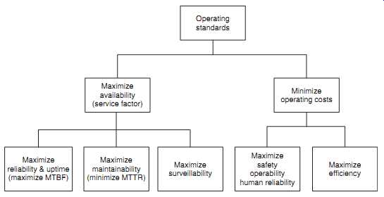 Fig. 6 shows the relationship of the concepts just discussed.
=====
Operating standards Minimize operating costs Maximize availability (service factor) Maximize reliability & uptime (maximize MTBF)
Maximize maintainability (minimize MTTR) Maximize surveillability
Maximize safety operability human reliability Maximize efficiency Fig. 6. Reliability and uptime relationships.