AMAZON multi-meters discounts AMAZON oscilloscope discounts
<< cont. from part 1
Installation
Nonmetallic-sheathed cable is probably the least expensive of the various wiring methods. It is relatively lightweight and easy to install. It is widely used for dwelling unit installations on circuits of 600 volts or less. FIG. 10 shows an example of a stripper used for stripping nonmetallic-sheathed cable. A razor knife also works fine with care. The installation of nonmetallic-sheathed cable must con form to the requirements of NEC Article 334. Refer to FIGs. 11, 12, 13, 14, 15, and 16.
• The cable must be strapped or stapled not more than 12 in. (300 mm) from a box or fitting.
• Do not staple flat nonmetallic-sheathed cables on edge, FIG. 15.
• Unless run through horizontal holes or notches in studs and joists, the intervals between straps or staples must not exceed 4 1/2 ft (1.4 m).
• Exposed runs of cables can be subjected to lots of abuse. A child may pull or stand on the cables and adults may use the cables to hang things on.
NEC 334.15 requires that cables be protected against physical damage where necessary. For example, where exposed in a garage with open studs, run the cables on the sides of the studs. Where cables are run horizontally from or through stud to stud, protection is required.
Some inspectors require protective boards over exposed horizontal cable runs, or sheet rock, or other wall finish up to the ceiling, or at least 7 ft (2.13 m) up. For protection of cables in attics, see Section 15.
• The 4 1/2 ft (1.4 m) securing requirement is not needed where nonmetallic-sheathed cable is run horizontally through holes in wood or metal framing members (studs, joists, rafters, etc.). The cable is considered to be adequately supported by the framing members, NEC 334.30(A).
• The inner edge of the bend shall have a mini mum radius not less than 5 times the cable diameter, NEC 334.24.
• The cable must not be used in circuits of more than 600 volts.
• CAUTION: Be very careful when installing staples. Driving them too hard can squeeze and damage the insulation on the conductors, causing short circuits and/or ground faults.
• See FIG. 11 for special conditions when using single-gang nonmetallic device boxes.
• Nonmetallic-sheathed cable must be protected where passing through a floor by at least 6 in. (150 mm) of rigid metal conduit, intermediate metal conduit, electrical metallic tubing, Schedule 80 rigid PVC conduit, or other approved means, NEC 334.15(B). A fitting (bushing or connector) must be used at both ends of the conduit to protect the cable from abrasion, FIG. 12.
• When nonmetallic-sheathed cables are "bundled" or "stacked" for distances of more than 24 in. (600 mm) without maintaining spacing, their ampacities must be reduced (adjusted, derated) according to Table 310.15(B)(3)(a). When cables are bundled together, the heat generated by the conductors cannot easily dissipate. See FIG. 13(A).
• When more than two nonmetallic-sheathed cables are installed through the same opening in wood framing members that are to be fire- or draft-stopped with thermal insulation, caulk, or sealing foam, and there is no spacing between the cables, their conductor ampacities shall be adjusted according to NEC Table 310.15(B)(3)(a). See NEC 334.80 and FIG. 13(B).
• When Type AC and Type MC cables are "bundled" or "stacked" without maintaining spacing, derating is not necessary if the following is true:
- The conductors are 12 AWG copper.
- The bundling or stacking is not more than 24 in. (600 mm).
- There are no more than three current carrying conductors in each cable.
- There are no more than 20 current-carrying conductors in the bundle.
When there are more than 20 current carrying conductors in the bundle, for a length greater than 24 in. (600 mm) a 60% adjustment factor shall be applied. See NEC 310.15(B)(3)(a)(4) and (B)(3)(a)(5).
• Type NM cable may be run in unsupported lengths of not more than 4 1/2 ft (1.4 m) between the last point of support of the cable and a luminaire or other equipment within an accessible ceiling. For this last 4 1/2 ft (1.4 m), the 12-in. (300-mm) and 4 1/2-ft (1.4-m) securing requirements mentioned above are not necessary if the nonmetallic-sheathed cable is used as a luminaire (fixture) whip to connect luminaires of other equipment; see NEC 334.30. Luminaire (fixture) whips are discussed in Section 7 and Section 17.
FIG. 16 shows the installation of nonmetallic sheathed cable in unfinished basements and crawl spaces, 334.15(C).
See Section 15 and Figures 13 and Figure 14 for additional text and diagrams covering the installation of cables in attics.
FIG. 11 shows the Code requirements for securing nonmetallic-sheathed cable when using nonmetallic boxes.
The Code in 314.40(D) requires that all metal boxes have provisions for the attachment of an equipment grounding conductor. FIG. 17 shows a gang-type switch (device) box that is tapped for a screw by which the grounding conductor may be connected underneath. FIG. 18 shows an outlet box, also with provisions for attaching grounding conductors. FIG. 19 illustrates the use of a small grounding clip.
NEC 410.44 requires that there be a provision whereby the equipment grounding conductor can be attached to the exposed metal parts of luminaires.
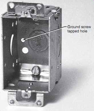
FIG. 17 Gang-type switch (device) box.
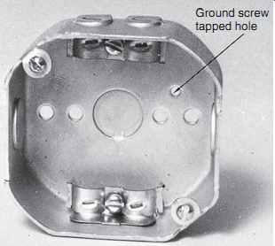
FIG. 18 Outlet box.
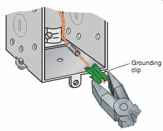
FIG. 19 Method of attaching ground clip to a metal switch (device) box;
see 250.148.
Are Cables Permitted in Raceways?
Yes, but only if certain conditions are met.
NEC 300.15(C) permits using a listed conduit or tubing without a box where the conduit or tubing is used to protect a nonmetallic-sheathed cable against physical damage. FIG. 20 shows an example of this in a basement where the wiring method in the ceiling is NM cable and a switch or receptacle is in a box mounted on the wall. An EMT is installed from the box to a point above the ceiling joists, where the EMT is secured to the side of the joists. The NM cable is then run inside the EMT, and an insulating fitting is installed on the upper end of the tubing to protect the cable against abrasion. The cable does not require securing inside the raceway, 334.30. The finished job is neat.
The conductors inside a nonmetallic-sheathed cable meet all of the UL requirements for Type THHN conductors but are not surface marked in any manner.
NEC 334.15(B) requires protection of nonmetallic sheathed cable from physical damage where necessary.
This section lists different types of raceways permit ted to be used for protection of the cable.
The raceway fill for a cable in a conduit or tubing is based on the allowable percentage fill values specified in Table 1, Section 9.
Alternate Method of Installing NM above Panel Nonmetallic-sheathed cables are usually secured to a panel, box, or cabinet, with a cable clamp or connector. For surface-mounted enclosures only, 312.5(C), Exception, provides an alternate method for running nonmetallic-sheathed cables, as illustrated in FIG. 21.

FIG. 20 An example of EMT protecting a nonmetallic-sheathed cable from
physical damage where the cable is run down the wall of an unfinished basement.
This also makes a neat installation.
The EMT and the metal box must be grounded. Physical protection and grounding are required by 334.15(C). NEC 300.18(A), Exception, also recognizes this type of installation.
Be aware of a significant rule in Note 9 to NEC Table 1 of Section 9. This note requires that if cables with elliptical cross sections are installed in a raceway, the cross-sectional area of the cable is determined by assuming the greater dimension is the diameter of a circle. This rule is needed because some installers do not straighten the cables before installing them through the race way but pull them out of the center of a carton, which results in the cables twisting inside the raceway.
Let's do a calculation using a 12-2 W/G Type NM cable that is 1/4 in. 3 1/2 in. in size. We will assume the 1/2 in. dimension is the diameter of a circle and perform the calculation using the following formula:
A = pi x r^2
A = 3.14159 x (0.25 x 0.25)
A = 3.14159 x 0.0625
A = 0.1963 Sq.In.
============
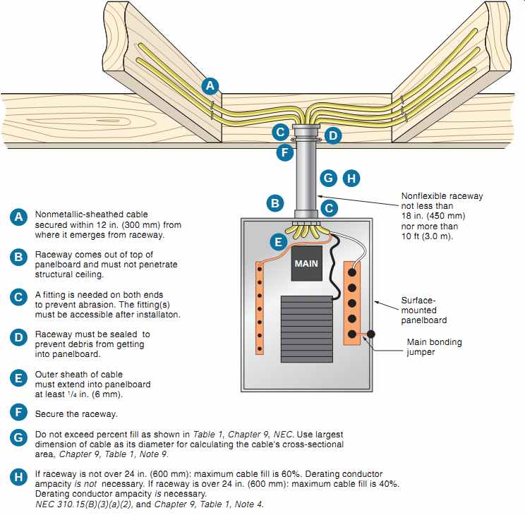
FIG. 21 An alternate method for running nonmetallic-sheathed cables into
a surface-mounted panel. This is permitted for surface-mounted panels only,
312.5(C), Exception.
Nonmetallic-sheathed cable secured within 12 in. (300 mm) from where it emerges from raceway.
Raceway comes out of top of panelboard and must not penetrate structural ceiling.
A fitting is needed on both ends to prevent abrasion. The fitting(s) must be accessible after installation.
Raceway must be sealed to prevent debris from getting into panelboard.
Outer sheath of cable must extend into panelboard at least 1/4 in. (6 mm).
Secure the raceway.
Do not exceed percent fill as shown in Table 1, Section 9, NEC. Use largest dimension of cable as its diameter for calculating the cable's cross-sectional area, Section 9, Table 1, Note 9.
If raceway is not over 24 in. (600 mm): maximum cable fill is 60%. Derating conductor ampacity is not necessary. If raceway is over 24 in. (600 mm): maximum cable fill is 40%.
Derating conductor ampacity is necessary.
NEC 310.15(B)(3)(a)(2), and Section 9, Table 1, Note 4.
============
Let's look at the following table to determine how many of these cables we are permitted to install in various sizes of EMT and whether derating is required.
Be sure to comply with all the conditions stated in NEC 312.5(C) Exception. Also be aware Type NM cable is limited to installation in dry locations and thus the installation in EMT as described above is not permitted in damp or wet locations.
Identifying Nonmetallic-Sheathed Cables One nice thing about nonmetallic-sheathed cable, particularly that with a white outer jacket, is that at panelboards and device and outlet boxes, you can use a permanent marking pen to mark the outer jacket with a few words indicating what the cable is for. Examples: FEED TO ATTIC; FEED TO L.R.; FEED TO DINING ROOM RECEPTACLES; FEED TO PANEL; BC#6; TO OTHER 3-WAY SWITCH; SWITCH LEG TO CEILING LIGHT; TO OUTSIDE LIGHT; and so on.
By marking the cables when they are installed, confusion when making the connections is reduced considerably.
Another great idea is to make a sleeve by cutting off a short 2 in. length of NM cable, pulling out the conductors, then marking an identifying statement on the sleeve. Slide the sleeve over the specific conductors inside the panel or box.
Multifamily Dwellings
Nonmetallic-sheathed cable is permitted to be installed in one- and two-family dwellings and in multifamily dwellings where the building construction is Type III, Type IV, or Type V; see 334.12(A). Definitions of construction types are found in building codes, the glossary of this text, and in Annex E of the NEC.
For years, the NEC restricted nonmetallic sheathed cable to a maximum of three floors above finished grade. This limitation was removed in the 2002 NEC.
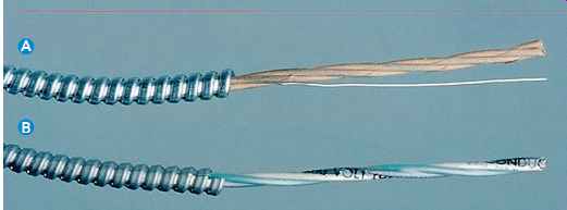
FIG. 22 (A) Type AC cable (Note paper wrap) (B) Type MC cable (AFC Cable
Systems, Inc., New Bedford, MA)
-----------------
Table 12 Comparisons of Type AC and Type MC cables.
[
Type AC (Article 320) Article 320: This article contains all of the installation requirements for the installation of Type AC armored cable.
320-1. Definition: Type AC cable is a fabricated assembly of insulated conductors in a flexible interlocked metallic armor.
Number of Conductors: Two to four current-carrying conductors plus bonding wire. It may also have a separate equipment grounding conductor.
Conductor Size and Type: 14 AWG through 1 AWG for copper conductors.
12 AWG through 1 AWG for aluminum conductors will be marked " AL " on a tag on the carton or reel.
12 AWG through 1 AWG for copper-clad aluminum conductors will be marked " AL (CU-CLAD)" or "Cu-Clad Al" on a tag on the carton or reel.
Color Coding: Two-conductor: one black, one white.
Three-conductor: one black, one white, one red.
Four-conductor: one black, one white, one red, one blue.
These are in addition to any equipment grounding and bonding conductors.
Bonding & Grounding: Type AC cable shall provide an adequate path for fault current. Type AC cable has a bonding wire or strip.
Bonding wire is in continuous direct contact with the metal armor. The bonding wire and armor act together to serve as the acceptable equipment ground. The bonding wire does not have to be terminated, just folded back over the armor. FIG. 23 shows how the bonding strip is folded back over the armor.
Never use the bonding strip as a grounded neutral conductor or as a separate equipment grounding conductor. It is an internal bonding strip-nothing more! Insulation: Type ACTHH has 90°C thermoplastic insulation, by far the most common.
Type ACTH has 75°C thermoplastic insulation. Type AC has thermo set insulation.
Type ACHH has 90°C thermoset insulation.
Conductors are individually wrapped with a flame retardant fibrous cover: light brown Kraft paper.
Author's comment: This is an easy way to distinguish Type AC from Type MC.
Armor: Galvanized steel or aluminum. Armored cable with aluminum armor is marked "Aluminum Armor."
Covering over armor: None Locations: Okay for dry locations.
Not okay for damp or wet locations.
Not okay for direct burial.
Insulating bushings: Required to protect conductor insulation from damage. Referred to as "antishorts," these keep any sharp metal edges of the armor from cutting the conductor insulation. Usually supplied in a bag with cable.
FIG. 23(A) shows an antishort being inserted.
FIG. 23(B) shows the recommended way of bending the bonding strip over the antishort to hold the antishort in place.
Minimum radius of bends: 53 diameter of cable. For small size cables, this is about the same curvature as a soda can.
Not available with "super neutral conductor." Not available with fiber-optic cables.
Support: Not more than 4½ ft (1.4 m) apart.
Not more than 12 in. (300 mm) from box or fitting.
Support not needed where cable is fished through walls and ceilings.
Cables run horizontally through holes in studs, joists, rafters, etc., are considered supported by the framing members.
Support not needed when used as a fixture whip within an accessible ceiling for lengths not over 6 ft (1.8 m) from last point of support.
Voltage: 600 volts or less.
Ampacity: Use the 60°C column of Table 310.15(B)(16). Derating permitted from 90°C column.
Thermal insulation: If buried in thermal insulation, the conductors must be rated 90°C.
Connectors: Set screw-type connectors not permitted with aluminum armor. Listed connectors are suitable for grounding purposes.
UL Standard 4. Because UL standards have evolved in numerical order, it is apparent that the armored cable standard is one of the first standards to be developed.
]
[
Type MC (Article 330)
Article 330: This article contains all of the installation requirements for the installation of Type MC metal-clad cable.
330.1. Definition: Type MC cable is a factory assembly of one or more insulated circuit conductors with or without optical fiber members and enclosed in an armor of interlocking metal tape or a smooth or corrugated metallic sheath.
Number of Conductors: Any number of current-carrying conductors. At least one manufacturer has a "Home Run Cable" that has conductors for more than one branch circuit, plus the equipment grounding conductors.
Conductor Size and Type: 18 AWG through 2000 kcmil for copper conductors.
12 AWG through 2000 kcmil for aluminum or copper-clad aluminum conductors.
12 AWG through 2000 kcmil for copper-clad aluminum conductors will be marked " AL (CU-CLAD)" or "Cu-Clad Al" on a tag on the carton or reel.
Color Coding: Two-conductor: one black, one white.
Three-conductor: one black, one white, one red.
Four-conductor: one black, one white, one red, one blue.
These are in addition to any equipment grounding and bonding conductors.
Bonding & Grounding: This has a separate green insulated equipment grounding conductor. It may have two equipment grounding conductors for isolated ground requirements, such as for computer wiring.
Unless specifically listed for grounding, the jacket of MC cable is not to be used as an equipment grounding conductor.
The sheath of smooth or corrugated tube Type MC is listed as acceptable as the required equipment grounding conductor.
Some MC cables have a full size bare aluminum conductor in continuous, direct contact with the metal armor. This bare conductor and the metal armor act together to serve as the acceptable equipment ground.
Cut off the bare conductor at the armor.
Insulation: Type MC has 90°C thermoplastic insulation.
Some Type MC has thermoset insulation.
Type MC cable is available with a PVC outer jacket suitable for direct burial.
No individual wrap. Has a polyester (Mylar) tape over all conductors. Some constructions have the extra layer of Mylar tape over the individual conductors. Has no bare bond wire but may have a full-size aluminum grounding/ bonding conductor. Author's comment: These are easy ways to distinguish Type AC from Type MC.
Armor: Galvanized steel, aluminum, or copper.
Three types:
Interlocked (most common). Requires a separate equipment grounding conductor. The armor by itself is not an acceptable equipment grounding conductor. Steel or aluminum.
Smooth tube. Does not require a separate equipment grounding conductor. Aluminum only.
Corrugated tube. Does not require a separate equipment grounding conductor. Copper or aluminum.
Covering over armor: Available with PVC outer covering.
Suitable for wet locations, for direct burial and concrete encasement if so covered.
Locations: Okay for wet locations if so listed.
Okay for direct burial if so listed.
Okay to be installed in a raceway.
Insulating bushings: Recommended but not required to protect conductor insulation from damage. Usually in a bag supplied with cable.
Minimum radius of bends: Smooth Sheath:
• 103 for sizes not over ¾ in. (19 mm) in diameter.
• 123 for sizes over ¾ in. (19 mm) and not over 1½ in. (38 mm) in diameter.
• 153 for sizes over 1½ in. (38 mm) in diameter.
Corrugated or interlocked:
• 73 diameter of cable.
Available with "super neutral conductor" when required for computer branch-circuit wiring. For example, three 12 AWG and one 10 AWG neutral conductor.
Available with power conductors and fiber-optic cables in one cable.
Support: Not more than 6 ft (1.8 m) apart.
Not more than 12 in. (300 mm) from box or fitting for cables having four or fewer 10 AWG or smaller conductors.
Support not needed where cable is fished through walls and ceilings.
Cables run horizontally through holes in studs, joists, rafters, etc., are considered supported by the framing members.
Support not needed when used as a fixture whip within an accessible ceiling for lengths not over 6 ft (1.8 m) from last point of support.
Voltage: 600 volts or less. Some MC has a voltage rating not to exceed 2000 volts.
Ampacity: Similar to wire pulled in raceways, determine in accordance with 310.15.
Thermal insulation: No mention in NEC. Type MC has 90°C thermoplastic insulation.
Connectors: Set screw-type connectors not permitted with aluminum armor. Listed connectors are suitable for grounding purposes.
UL Standard 1569.
]
------------------
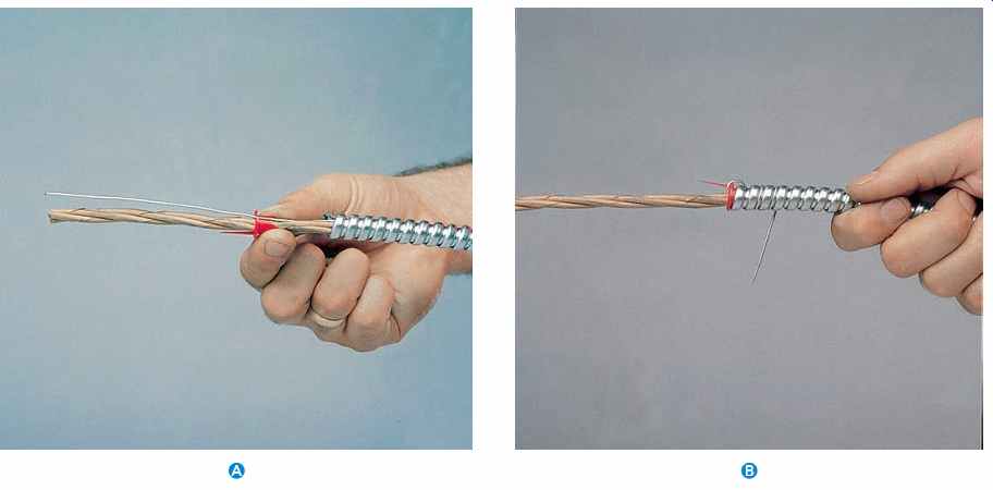
FIG. 23 Anti-short bushing prevents cutting of the conductor insulation
by the sharp metal armor.
ARMORED CABLE (TYPE AC) AND METAL-CLAD CABLE (TYPE MC)
Type AC and Type MC cables look very much the same (FIG. 22), yet there are significant differences.
Table 12 compares some of these differences.
To remove the outer metal armor, a rotary armor-cutting tool like that shown in FIG. 24 may be used.
If a hacksaw is used, make an angle cut on one of the armor's convolutions as long as the conductors need to be, perhaps 10-12 in. Be careful not to cut too deep or you might cut into the conductor insulation. Bend the armor at the cut and snap it off. Then slide the 10-12 in. of armor off the end of the cable. This method is not recommended by cable manufacturers because of the risk of damage to the insulated conductors. See FIG. 25.
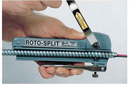
FIG. 24 This is an example of a tool that precisely cuts the outer armor
of armored cable, making it easy to remove the armor with a few turns of the
handle. (Seatek Co., Inc.)
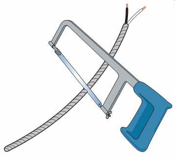
FIG. 25 Using a hacksaw to cut through a raised convolution of the cable
armor. This method is not recommended by manufacturers due to the risk of damaging
the conductors by cutting too deeply.
Most electricians, when using armored cable, will make three cuts with their hacksaw. The middle cut is where the cable and conductors will be cut off completely. The first and third cuts are where the armor will be snapped off. This saves time because it actually prepares two ends of the cable.
Most electricians still refer to armored cable as BX, supposedly derived from an abbreviation of the Bronx in New York City, where armored cable was once manufactured. BX was a trademark owned by the General Electric Company, but over the years it has become a generic term.
FIG. 22 shows armored cable with the armor removed to show the conductors that are wrapped with paper and the bare bonding wire.
Table 13 shows the uses and installation requirements for Type AC and Type MC cables for residential wiring.
Table 13 Uses and installation in dwellings (Type AC and Type MC).
INSTALLING CABLES THROUGH WOOD AND METAL FRAMING MEMBERS (300.4)
Wood Construction
When wiring a house, nonmetallic-sheathed cables are run through holes drilled in studs, joists, and other framing members. Typically, holes are drilled in the approximate centers of wood framing members. To avoid possible dam age to the cables, make sure that the edge of the hole is at least 1 1/4 in. (32 mm) from the nearest edge of the framing member, 300.4(A)(1). Refer to FIG. 26.
You have probably noticed that a 2 x 4 measures 1 1/2 in. 3 x 1/2 in., and that a 2 x 3 measures 1 1/2 in. x 2 1/2 in. This can present a real problem!
Steel Plates
If the 1 1/4 in. (32 mm) from the edge of hole to the edge of framing member cannot be maintained, or if the cable is laid in a notch, a steel plate(s) at least 1/16 in. (1.6 mm) thick must be used to protect the cable from errant nails or drywall screws, 300.4(A)(1). In all cases where the NEC requires 1/16-in. (1.6-mm) steel plates, listed and marked steel plates are permitted to be less than 1/16 in. (1.6 mm) because they have passed tough mechanical tests.
This permission is found in 300.4(A)(1) Exception 2, 300.4(A)(2) Exception 2, 300.4(B)(2) Exception, 300.4(D) Exception 3, and 300.4(E) Exception 2.
See FIG. 26.
Instead of using steel plates, FIG. 27 illustrates devices that can be used to stand off the cables from a framing member.
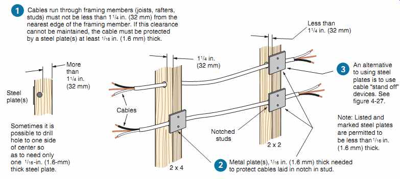
FIG. 26 Methods of protecting nonmetallic and armored cables so nails
and screws that "miss" the studs will not damage the cables, 300.4(A)(1)
and (2). Because of their strength, intermediate and rigid metal conduit, PVC
rigid conduit, and electrical metallic tubing are exempt from this rule per
the Exceptions found in 300.4. See FIG. 28 for alternative methods of protecting
cables.
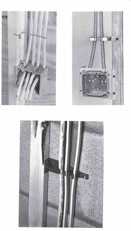
FIG. 27 Devices that can be used to meet the Code requirement to maintain
a 1¼-in. (32-mm) clearance from framing members.
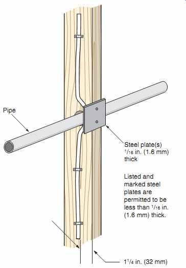
FIG. 28 Where it is necessary to cross pipes or other similar obstructions,
making it impossible to maintain at least 1¼-in. (32-mm) clearance from the
framing member to the cable, install a steel plate(s) at least 1/16-in. (1.6
mm) thick to protect the cable from possible damage from nails or screws.
See 300.4(A)(1) and (A)(2).
Cables Installed Parallel to Framing Members or Furring Strips
To protect nonmetallic-sheathed cables, armored cables, or nonmetallic raceways that are run parallel to framing members or furring strips from being damaged by drywall screws and nails, you have two choices: (1) keep them more than 1 1/4 in. (32 mm) from the nearest edge of the framing member or furring strip, or (2) use steel plates. Refer to 300.4(D), 320.17, and 334.17. See FIGs. 16, 26, 27, and 28.
Metal Construction
Metal studs are being used more and more. They don't burn and termites don't eat them. They are stronger than wood and can be set 20 in. (500 mm) on center instead of the usual 16-in. (400-mm) spacing.
Metal studs are 10 times more conductive than wood, so treatment of insulation must be addressed.
Where nonmetallic-sheathed cables pass through holes or slots in metal framing members, the cable must be protected by a listed bushing or listed grommet securely fastened in place prior to installing the cable. The bushing or grommet shall:
• remain in place during the wall finishing process,
• cover the complete opening, and
• be listed for the purpose of cable protection.
This information is found in 300.4(B)(1) and 334.17. See FIG. 29. Bushings that snap into a hole sized for the specific size bushing (1/2 in., 3/4 in., etc.), or a two-piece snap-in bushing that fits just about any size precut hole in the metal framing members are acceptable to use, as shown in FIG. 29. These types of bushings (insulators) are not required in metal framing members when the wiring method is armored cable, EMT, FMC, or electrical nonmetallic tubing.
When running nonmetallic-sheathed cable or electrical nonmetallic tubing through metal framing members where there is a likelihood that nails or screws could be driven into the cables or tubing, a steel plate, steel sleeve, or steel clip at least 1/16 in. (1.6 mm) thick must be installed to protect the cables and/or tubing. This is spelled out in 300.4(B)(2). See FIGs. 28 and 29.
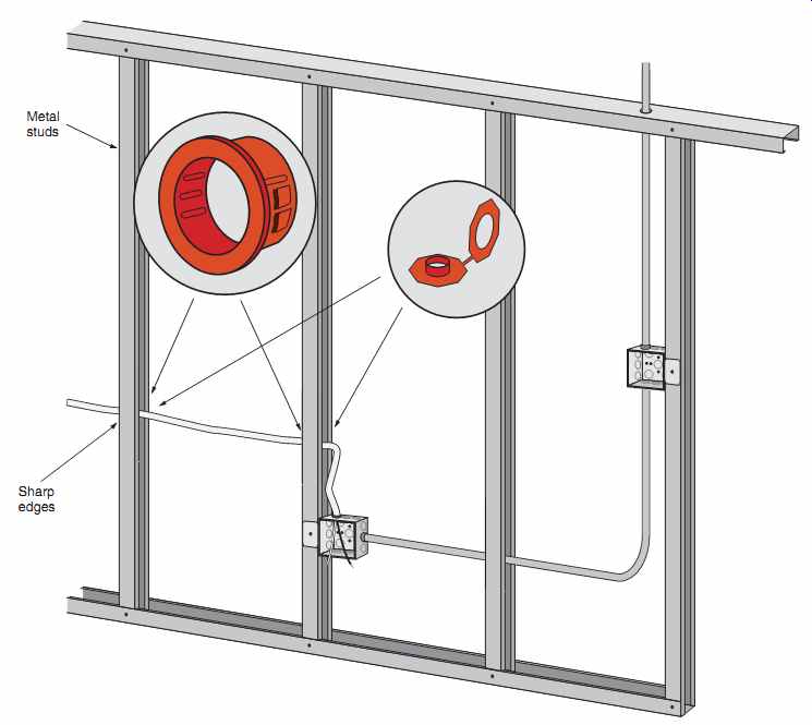
FIG. 29 NEC 300.4(B) and 334.17 require protection of nonmetallic-sheathed
cable where it runs through holes in metal framing members. Shown are two types
of listed bushings (grommets) that can be installed to protect nonmetallic-sheathed
cable from abrasion. Electricians generally avoid using nonmetallic-sheathed
cable through metal studs and joists. They use electrical metallic tubing,
flexible metal conduit, armored cable (Type AC or MC), or electrical nonmetallic
tubing. Where there is a likelihood that nails or screws might penetrate the
nonmetallic-sheathed cable, 1/16-in. (1.6-mm) thick steel plates, sleeves,
or clips must be installed to protect the cable or electrical nonmetallic tubing.
CABLES IN SHALLOW GROOVES AND CHASES
NEC 300.4(F) addresses the wiring problems associated with cutting grooves into building material because there is no hollow space for the wiring. Nonmetallic-sheathed cable and some raceways must be protected when laid in a groove.
Protection must be provided with a 1/16-in. (1.6-mm) steel plate(s), sleeve, or equivalent, or the groove must be deep enough to allow not less than 1 1/4-in. (32-mm) free space for the entire length of the groove. This situation can be encountered where styrofoam insulation building blocks are grooved to receive the electrical cables, then covered with wallboard, wood paneling, or other finished wall material. Another typical example is where solid wood planking is installed on top of wood beams.
The top side of the planking is covered with roofing material, and the bottom side is exposed and serves as the finished ceiling. The only way to install wiring for ceiling luminaires and fans is to groove the planking in some manner, as shown in FIG. 30.
This additional protection is not required when the raceway is intermediate metal conduit (Article 342), rigid metal conduit (Article 344), rigid PVC conduit (Article 352), or electrical metallic tubing (Article 358) (see FIG. 29).
NEC 334.30(B)(1), and 300.4(D), Exception 2, allow cables to be "fished" between outlet boxes or other access points without additional protection.
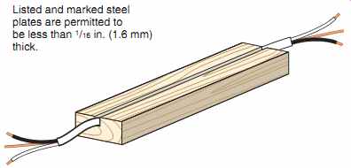
FIG. 30 Example of how a solid wood framing member or Styrofoam insulating
block might be grooved to receive the nonmetallic sheathed cable. After the
cable is laid in the groove, a steel plate(s) not less than 1/16-in. (1.6-mm)
thick must be installed over the groove to protect the cable from damage, such
as from driven nails or screws. See 300.4(F) and 334.15(B).
In the recreation room of the residence plans, precautions must be taken so there is adequate protection for the wiring. The walls in the recreation room are to be paneled. Therefore, if the carpenter uses 1 x 2 or 2 x 2 furring strips, as in FIG. 31, nonmetallic-sheathed cable would require the additional 1/16-in. (1.6-mm) steel plate(s) protection or the use of stand off devices similar to those illustrated in FIG. 27.
Some building contractors attach 1-in. insulation to the walls, then construct a 2 x 4 wall in front of the basement structural foundation wall, leaving 1-in. spacing between the insulation and the back side of the 2 x 4 studs. This makes it easy to run cables or conduits behind the 2 x 4 studs and eliminates the need for the additional mechanical protection, as shown in FIG. 32.
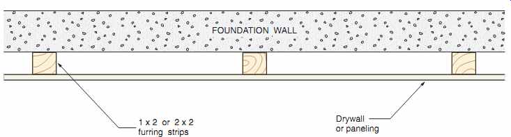
FIG. 31 When 1 x 2 or 2 x 2 furring strips are installed on the surface
of a basement wall, additional protection, as shown in FIGs. 26, 27,
29, and 30, must be provided. It is impossible to maintain the minimum
distance of 1¼ in. (32 mm) from the nearest edge of the framing member, in
which case protection is required the entire length of the cable run, 300.4(D).
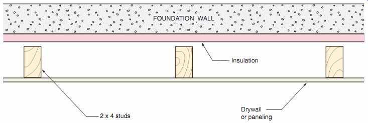
FIG. 32 This sketch shows how to insulate a foundation wall and how to
construct a wall that provides a space to run cables and/or raceways that will
not require the additional protection as shown in FIGs. 26, 27, 29,
and 30.
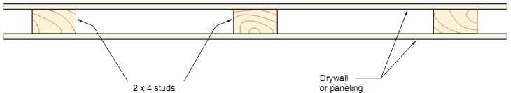
FIG. 33 When 2 x 4 studs are installed "flat," such as might
be found in nonbearing partitions, cables running parallel to or through the
studs must be protected against the possibility of having nails or screws driven
through the cables. This means protecting the cable with 1/16-in. (1.6-mm)
steel plates or equivalent for the entire length of the cable, or installing
the wiring using intermediate metal conduit, rigid metal conduit, rigid PVC
conduit, or EMT. See FIGs. 26, 27, 28, and 29.
Watch out for any wall partitions where 2 x 4 studs are installed "flat," as in FIG. 33. In this case, the choice is to provide the required mechanical protection as required by 300.4, or to install the wiring in EMT.
See Section 15 concerning the installation of cables in attics.
Building Codes
When complying with the NEC, be sure to also comply with the building code. Building codes are concerned with the weakening of framing members when drilled or notched. Meeting the requirements of the NEC can be in conflict with building codes and vice versa. Here is a recap of some of the key building code requirements found in the ICC International Residential Code.
Studs:
• Cuts or notches in exterior or bearing partitions shall not exceed 25% of the stud's width.
• Cuts or notches in nonbearing partitions shall not exceed 40% of the stud's width.
• Bored or drilled holes in any stud:
- shall not be greater than 40% of the stud's width,
- shall not be closer than 5/8 in. (15.9 mm) to the edge of the stud, and
- shall not be located in the same section as a cut or notch.
Joists:
• Notches on the top or bottom of joists shall not exceed 1/6 the depth of the joist, shall not be longer than 1/3 the width of the joists, and shall not be in the middle third of the joist.
• Holes bored in joists shall not be within 2 in.
(50 mm) of the top or bottom of the joist or any other hole, and the diameter of any such hole shall not exceed 1/3 the depth of the joist. If the joist is also notched, the hole shall not be closer than 2 in. (50 mm) to the notch.
Engineered Wood Products
Today, we find many homes constructed with engineered wood I-joists and beams. The strength of these factory-manufactured framing members conforms to various building codes. It is critical that certain precautions be taken relative to drilling and cutting these products so as not to weaken them. In general:
• Do not cut, notch, or drill holes in trusses, laminated veneer lumber, glue-laminated members, or I-joists unless specifically permitted by the manufacturer.
• Do not cut, drill, or notch flanges. Flanges are the top and bottom pieces.
• Do not cut holes too close to supports or to other holes.
• For multiple holes, the amount of web to be left between holes must be at least twice the diameter of the largest adjacent hole. The web is the piece between the flanges.
• Holes not over 1 1/2 in. (38 mm) usually can be drilled anywhere in the web.
• Do not hammer on the web except to remove knockout pre-scored holes.
• Check and follow the manufacturer's instructions!
INSTALLATION OF CABLES THROUGH DUCTS
NEC 300.22 is extremely strict as to what types of wiring methods are permitted for installation of cables through ducts or plenum chambers. These stringent rules are for fire safety.
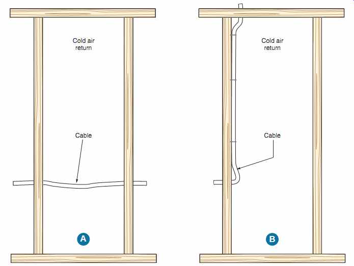
The Code requirements are somewhat relaxed by 300.22(C), Exception. In this exception, permission is given to run nonmetallic-sheathed and armored cables in joist and stud spaces (i.e., cold air returns), but only if they are run perpendicular to the long dimensions of such spaces, as illustrated in FIG. 34.
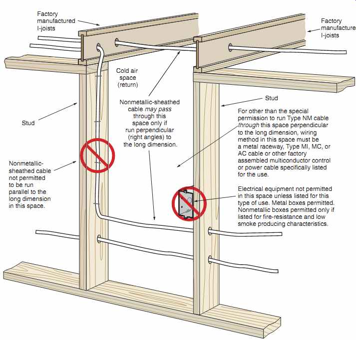
FIG. 34 Nonmetallic-sheathed cable may pass through cold air return, joist,
or stud spaces in dwellings, but only if it is run at right angles to the long
dimension of the space, 300.22(C), Exception.
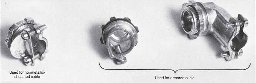
FIG. 35 Cable connectors.
CONNECTORS FOR INSTALLING NONMETALLIC SHEATHED AND ARMORED CABLE
The connectors shown in FIG. 35 are used to fasten nonmetallic-sheathed cable and armored cable to manufacturer's installation instructions, the specific NEC article, and the UL White Book.
Grounding. All listed fittings for listed metallic raceways and listed metal jacketed cables are tested to carry a specified amount of fault current for a specified length of time, making the fittings accept able for grounding when properly installed.
In this residence, the wiring method for all of the exposed wiring in the workshop is to be electrical metallic tubing (EMT). Wiring with EMT is covered in detail in Section 18.
Table 14 provides a summary of the requirements for installing intermediate metal conduit (IMC), rigid metal conduit (RMC), rigid polyvinyl chloride conduit (PVC), and electrical metallic tubing (EMT).
FLEXIBLE CONNECTIONS
The installation of some equipment requires flexible connections, both to simplify the installation and to stop the transfer of vibrations. In residential wiring, flexible connections are used to connect equipment such as attic fans, food waste disposers, dishwashers, air conditioners, heat pumps, and recessed luminaires.
the boxes and panels in which they terminate. These connectors clamp the cable securely to each outlet box. Many boxes have built-in clamps and do not require separate connectors.
The question continues to be asked: May more than one cable be inserted in one connector? Unless the UL listing of a specific cable connector indicates that the connector has been tested for use with more than one cable, the rule is one cable, one connector. Connectors suitable for more than one cable will be marked on the carton.
Table 14 Conduit and tubing.
FIG. 36 Code requirements for securing and supporting raceways are found in 342.30 (intermediate metal conduit), 344.30 (rigid metal conduit, 352.30 (rigid PVC conduit), and 358.30 (electrical metallic tubing).
Table 15 Maximum distance between supports for rigid PVC conduit.
INTERMEDIATE METAL CONDUIT (ARTICLE 342), RIGID METAL CONDUIT (ARTICLE 344), RIGID PVC CONDUIT (ARTICLE 352), AND ELECTRICAL METALLIC TUBING (ARTICLE 358)
Some communities do not permit cable wiring.
They require that the wiring method be a raceway- metallic or nonmetallic. You will have to check this out before starting a project.
The following comparison chart provides the highlights of the NEC requirements for different types of raceways that might be used in a residence. For more detailed information, refer to the following Table 16 shows the NEC requirements for three types of commonly used flexible conduit.
Table 16 Flexible connections.
ELECTRICAL NONMETALLIC TUBING (ENT) (ARTICLE 362)
Electrical nonmetallic tubing (ENT) is covered in Article 362 of the NEC. It is a pliable, lightweight, corrugated raceway made of PVC. It requires fittings made specifically for the ENT. FIG. 44 shows color-coded ENT and some fittings. Color-coded ENT can be used to differentiate power, communication, and fire protection signaling system.
Although not often used in typical house wiring, some electricians find ENT very practical for providing a raceway system for installing structured wiring conductors and cables. Structured wiring is discussed in Section 31.
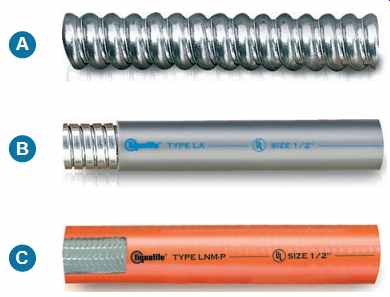
FIG. 37 (A) Flexible metal conduit.
(B) Liquidtight flexible metal conduit.
(C) Liquidtight flexible nonmetallic conduit. (Electri-Flex Co.)
SERVICE-ENTRANCE CABLE (ARTICLE 338)
Service-entrance cable is covered in Article 338 of the NEC.
Service-entrance cable is defined as a single conductor or multi-conductor assembly provided with or without an overall covering, primarily used for services.
Where permitted by local electrical codes, service-entrance cable is most often run from the utility's service drop (service point) to the meter base, then from the meter base to the main service panelboard.
It is also permitted as a branch circuit to connect major electrical appliances and as a feeder to a subpanel. Four-wire cable with three insulated conductor and a bare equipment grounding conductor is required for feeders to panelboards as well as to appliances such as electric ranges and dryers. For these situations, the choice of whether to use Type SE cable or nonmetallic-sheathed cable becomes a matter of choice, the major issue being the cost of the cable. Some Type SE cable with aluminum conductors may cost less than that for nonmetallic sheathed cable with copper conductors. The labor for the installation of either type is the same.
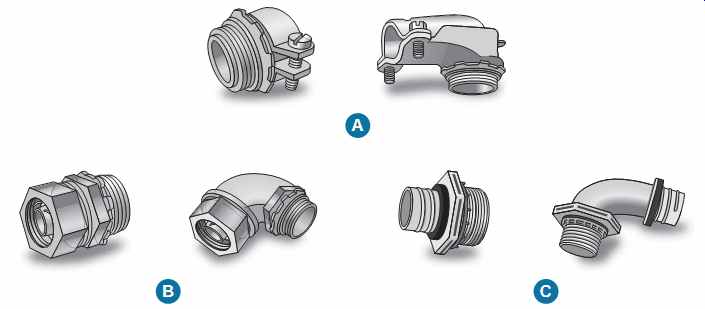
FIG. 38 Various fittings for (A) flexible metal conduit, (B) liquidtight
flexible metal conduit, and (C) liquidtight flexible nonmetallic conduit.
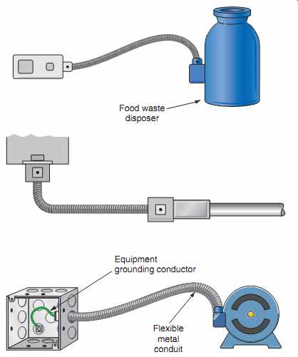
FIG. 39 If FMC or LFMC are serving as an equipment ground return path,
the total length shall not exceed 6 ft (1.8 m). Refer to 250.118(5)c, and 250.118(6)d.
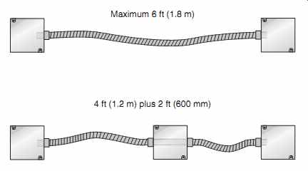
FIG. 40 The "combined" length of flexible metal conduit and
liquidtight flexible metal conduit shall not exceed 6 ft (1.8 m) to serve as
a ground return path, 250.118(5)c, and 250.118(6)d.
There are two styles of Type SE cable: SER and SEU. Table 17 shows the NEC installation requirements and the key differences in construction of these cables. See Table 17 and FIG. 45.
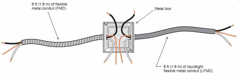
FIG. 41 Use of liquidtight flexible metal conduit or flexible liquidtight
nonmetallic conduit.
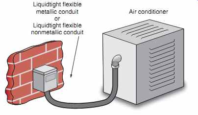
FIG. 42 Some of the more common places where flexible onnections could
be used.
============
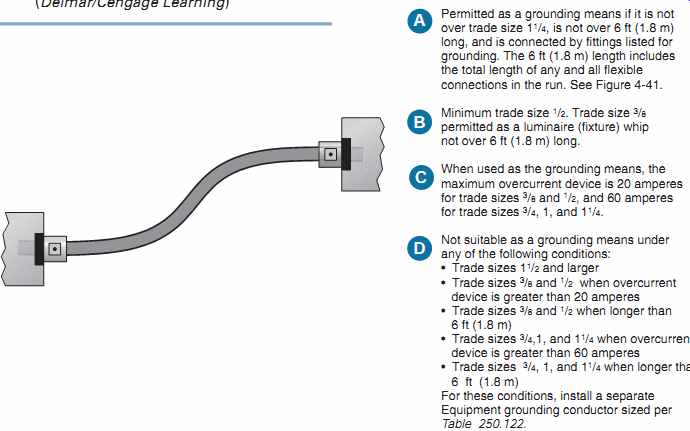
FIG. 43 Grounding capabilities of liquidtight flexible metal conduit (LFMC).
Permitted as a grounding means if it is not over trade size 1 1/4, is not over 6 ft (1.8 m) long, and is connected by fittings listed for grounding. The 6 ft (1.8 m) length includes the total length of any and all flexible connections in the run. See FIG. 41.
Minimum trade size 1/2. Trade size 3/8 permitted as a luminaire fixture) whip not over 6 ft (1.8 m) long.
When used as the grounding means, the maximum overcurrent device is 20 amperes for trade sizes 3/8 and 1/2, and 60 amperes for trade sizes 3/4, 1, and 1 1/4.
Not suitable as a grounding means under any of the following conditions:
- Trade sizes 1 1/2 and larger
- Trade sizes 3/8 and 1/2 when overcurrent device is greater than 20 amperes
- Trade sizes 3/8 and 1/2 when longer than 6 ft (1.8 m)
- Trade sizes 3/4,1, and 1 1/4 when overcurrent device is greater than 60 amperes
- Trade sizes 3/4, 1, and 11/4 when longer than 6 ft (1.8 m)
For these conditions, install a separate
Equipment grounding conductor sized per Table 250.122.
============
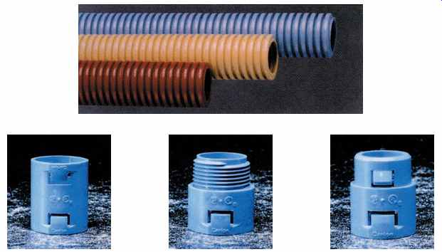
FIG. 44 Color-coded ENT, a coupling, a threaded connector, and a snap-in
connector.
Table 17 Service-entrance cables Type SE, SER, SEU, and USE comparisons.
Type UF Cable (Article 340)
Type UF is an underground feeder and branch circuit cable. Type UF cable is discussed in Section 16.
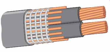
FIG. 45 Type SEU service-entrance cable. The major characteristic is the
uninsulated wraparound neutral conductor.
See Table 17 for NEC requirements for the permitted uses of Type SE cables.
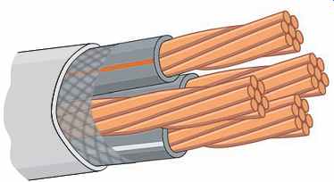
FIG. 46 Type SER service-entrance cable.
The major characteristics are the insulated neutral conductor and bare equipment grounding conductor. See Table 17 for NEC requirements for the permitted uses of Type SE cables.
QUIZ
Note: Refer to the Code or the plans where necessary.
1. The largest size solid conductor permitted to be installed in a raceway is (10 AWG) (8 AWG) (6 AWG). Circle the correct answer.
2. What is the minimum branch-circuit wire size that may be installed in a dwelling?
3. What exceptions, if any, are there to the answer for Question 2?
4. What determines the ampacity of a wire?
5. What unit of measurement is used for the diameter of wires?
6. What unit of measurement is used for the cross-sectional area of wires?
7. What is the voltage rating of the conductors in Type NMC cable?
8. Indicate the allowable ampacity of the following Type THHN (copper) conductors.
Refer to Table 310.15(B)(16).
a. 14 AWG ______ amperes
b. 12 AWG ______ amperes
c. 10 AWG ______ amperes
d. 8 AWG ______ amperes
e. 6 AWG ______ amperes
f. 4 AWG ______ amperes
9. What is the maximum operating temperature of the following conductors? Give the answer in degrees Celsius.
a. Type XHHW __
b. Type THWN __
c. Type THH __
d. Type TW ____
10. What are the colors of the conductors in nonmetallic-sheathed cable for:
a. 2-wire cable? ______ , ______
b. 3-wire cable? ______ , ______ , ______
11. For nonmetallic-sheathed cable, may the uninsulated conductor be used for purposes other than grounding?
12. What size equipment grounding conductor is used with the following sizes of nonmetallic-sheathed cable?
a. 14 AWG __
b. 12 AWG __
c. 10 AWG __
d. 8 AWG ___
13. Under what condition may nonmetallic-sheathed cable ( Type NM) be fished in the hollow voids of masonry block walls?
14. a. What is the maximum distance permitted between straps on a cable installation?
b. What is the maximum distance permitted between a box and the first strap in a cable installation?
c. Does the NEC permit 2-wire Romex stapled on edge?
d. When Type NMC cable is run through holes in studs and joists, must additional support be provided?
15. What is the difference between Type AC and Type ACT armored cables?
16. Type ACT armored cable may be bent to a radius of not less than ______ times the diameter of the cable.
17. When armored cable is used, what protection is provided at the cable ends?
18. What protection must be provided when installing a cable in a notched stud or joist, or when a cable is run through bored holes in a stud or joist where the distance is less than 1 1/4 in. (32 mm) from the edge of the framing member to the cable, or where the cable is run parallel to a stud or joist and the distance is less than 1 1/4 in. (32 mm) from the edge of the framing member to the cable?
19. For installing directly in a concrete slab, (armored cable) (nonmetallic-sheathed cable) (conduit) may be used. Circle the correct method of installation.
20. Circle the correct answer to the following statements:
a. Type SE service-entrance cable is for aboveground use. True | False
b. Type USE service-entrance cable is suitable for direct burial in the ground. True | False
c. Type SE cable with an uninsulated neutral conductor is permitted for hooking up an electric range. True |False
d. Type SE cable with an insulated neutral conductor is permitted for hooking up an electric range. True | False
e. Are Types SE and USE service-entrance cables used in your area? Yes | No
21. When running NMC through a bored hole in a stud, the nearest edge of the bored hole shall not be less than ______ in. from the face of the stud unless the cable is protected by a 1/16 in. (1.6 mm) metal steel plate(s).
22. Where is the main service-entrance panel located in this residence?
23. a. Is nonmetallic-sheathed cable permitted in your area for residential wiring? b. From what source is this information obtained?
24. Is it permitted to use flexible metal conduit over 6 ft (1.8 m) in length as a grounding means? (Yes) (No) Circle the correct answer.
25. Liquidtight flexible metal conduit may serve as a grounding means in sizes up to and including ______ in. where used with listed fittings.
26. The allowable current-carrying capacity (ampacity) of aluminum wire, or the maximum overcurrent protection in the case of 14 AWG, 12 AWG, and 10 AWG conductors, is less than that of copper wire for a given size, insulation, and tempera ture of 30°C. Refer to Table 310.15(B)(16) and 240.4(D) and complete the following table. Important: Where the ampacity of the conductor does not match the rating of a standard fuse or circuit breaker as listed in 240.6(A), 240.4(B) permits the selection of the next "higher" standard rating of fuse or circuit breaker if the next higher standard rating does not exceed 800 amperes. Nonstandard ampere ratings are also permitted.
27. It is permissible for an electrician to connect aluminum, copper, or copper-clad aluminum conductors together in the same connector. (True) (False) Circle the correct answer.
28. Terminals of switches and receptacles marked CO/ALR are suitable for use with ____, ____, and ____ conductors.
29. Wire connectors marked AL/CU are suitable for use with ______, ______, and ______ conductors.
30. A wire connector bearing no marking or reference to AL, CU, or ALR is suitable for use with (copper) (aluminum) conductors only. Circle the correct answer.
31. When Type NM or NMC cable is run through a floor, it must be protected by at least ______ in. (______ mm) of ___
32. When nonmetallic-sheathed cables are bunched or bundled together for distances longer than 24 in. (600 mm), what happens to their current-carrying ability?
33. In diagrams A and B, nonmetallic-sheathed cable is run through the cold air return. Which diagram "meets Code"? A ______ B ______ Check one.
34. The marking on the outer jacket of a nonmetallic-sheathed cable indicates the letters NMC-B. What does the letter "B" signify?
35. A 120-volt branch circuit supplies a resistive heating load of 10 amperes. The distance from the panel to the heater is approximately 140 ft. Calculate the voltage drop using (a) 14 AWG, (b) 12 AWG, (c) 10 AWG, (d) 8 AWG copper conductors. See 210.19(A), Informational Note No. 4 and 215.2(A)(3), Informational Note No. 2.
36. In Question 35, it is desired to keep the voltage drop to 3% maximum. What mini mum size wire would be installed to accomplish this 3% maximum voltage drop? See 210.19(A), Informational Note No. 4 and 215.2(A)(3), Informational Note No. 2.
37. NEC 215.2, 220.61, 230.42, and 310.15(B)(7) state that the neutral conductor of a residential service or feeder can be smaller than the phase conductors, but only ____
38. The allowable ampacity of a 4 AWG THHN from Table 310.15(B)(16) is 95 amperes.
What is this conductor's ampacity if connected to a terminal listed for use with 60°C wire?
39. If, because of some obstruction in a wall space, it is impossible to keep an NMC cable at least 1 1/4 in. (32 mm) from the edge of the stud, then it shall be protected by a metal plate at least ____ in. thick.
40. The recessed fluorescent luminaires installed in the ceiling of the recreation room of this residence are connected with trade size 3/8 flexible metal conduit. These flexible connections are commonly referred to as fixture whips. Does the flexible metal conduit provide adequate grounding for the luminaires, or must a separate equipment grounding conductor be installed?
41. Flexible liquidtight metal conduit will be used to connect the air-conditioner unit. It will be trade size 3/4. Must a separate equipment grounding conductor be installed in this FLMC to ground the air conditioner properly?
42. What size overcurrent device protects the air-conditioning unit?
43. May the 20-ampere small-appliance branch circuits in the kitchen of a residence also supply the lighting above the kitchen sink and under-cabinet lighting? Check the correct answer. Yes ______ No ______
44. A 30-ampere branch circuit is installed for an electric clothes dryer. What is the maxi mum ampere rating of a dryer permitted by the NEC to be cord-and-plug-connected to this circuit? Check the correct answer.
a. ______ 30 amperes
b. ______ 24 amperes
c. ______ 15 amperes
45. In many areas, metal framing members are being used in residential construction.
When using nonmetallic-sheathed cable, what must be used where the cable is run through the metal framing members?
46. Are set-screw-type connectors permitted to be used with armored cable that has an aluminum armor?
47. Most armored cable today has 90°C conductors. What is the correct designation for this type of armored cable?
48. If you saw two different types of SE cables, how would you distinguish them?
49. Circle the correct answer defining the type of location:
a. A raceway installed underground (Dry) (Wet)
b. A raceway installed in a concrete slab that is in direct contact with the earth (Dry) (Wet)
c. A raceway installed in a concrete slab between the first and second floor (Dry) (Wet)
d. A raceway installed on the outside of a building exposed to the weather (Dry) (Wet)
e. The interior of a raceway installed on the outside of a building exposed to the weather (Dry) (Wet)
Prev. | Next
Similar Articles