AMAZON multi-meters discounts AMAZON oscilloscope discounts
OBJECTIVES
• determine the current-carrying capacity (ampacity) of conductors.
• understand overcurrent protection for conductors and maximum loading of branch circuits.
• understand aluminum conductors and the possible fire hazards if they are not properly installed.
• know the NEC installation requirements for all types of cables and raceways.
• understand the special ampacity ratings of service entrance conductors.
• make voltage-drop calculations.
• learn an alternate cost and time-saving method permitted to bring nonmetallic-sheathed cables into the top of a surface-mounted panel.
CONDUCTORS
Throughout this text, all references to conductors are for copper conductors, unless otherwise stated.
Wire Size
The copper wire used in electrical installations is graded for size according to the American Wire Gauge (AWG) Standard. The wire diameter in the AWG standard is expressed as a whole number. The higher the AWG number, the smaller the wire. AWG sizes vary from fine, hair-like wire used in coils and small transformers to very large diameter wire required in industrial wiring to handle heavy loads.
The wire may be a single strand (solid conductor), or it may consist of many strands. Each strand of wire acts as a separate conducting unit. The wire size used for a circuit depends on the maximum current to be carried. The NEC in Table 210.24 shows that the minimum conductor size for branch circuit wiring is 14 AWG. Smaller size conductors are permitted for bell wiring, thermostat wiring, communications wiring, intercom wiring, luminaire wires, and similar low-energy circuits.
Don't Get Confused!
In the past, conductor size was shown as, for example, "No. 12 AWG." This same conductor now appears in the NEC as "12 AWG." The "12" is a size, not a quantity.
Table 1 shows typical applications for different size conductors.
Solid and Stranded Conductors For residential wiring, sizes 14, 12, and 10 AWG conductors are generally solid when the wiring method is nonmetallic-sheathed cable or armored cable.
==============
Table 1 Conductor applications chart.
[Conductor Size
20 AWG 18 AWG 16 AWG 14 AWG 12 AWG 10 AWG 8 AWG 6 AWG 4 AWG 3 AWG and larger ]
[ Overcurrent Protection
Class 2 circuit transformers provide overcurrent protection; see Article 725.
Class 2 circuit transformers provide overcurrent protection; see Article 725. For motor control circuits, 7 amperes, see Table 430.72(B).
Class 2 circuit transformers provide overcurrent protection; see Article 725. For motor control circuits, 10 amperes, see Table 430.72(B).
15 amperes 20 amperes 30 amperes 40 amperes 50 amperes 70 amperes 100 amperes
]
[
Typical Applications:
(Check wattage and/or ampere rating of load to select the correct size conductors based on Table 310.15(B)(16).) Telephone wiring is usually 20 or 22 AWG.
Low-voltage wiring for thermostats, chimes, security, remote control, home automation systems, etc. For these types of installations, 18 or 20 AWG conductors can be used depending on the connected load and length of circuit.
Same applications as above. Good for long runs to minimize voltage drop.
Typical lighting branch circuits.
Small-appliance branch circuits for the receptacles in kitchens and dining rooms. Also laundry receptacles, bathroom and workshop receptacles. Often used as the "home run" for lighting branch circuits. Some water heaters.
Most clothes dryers, built-in ovens, cooktops, some central air conditioners, some water heaters, some heat pumps.
Ranges, ovens, heat pumps, some large clothes dryers, large central air conditioners, heat pumps.
Electric ranges, electric furnaces, heat pumps.
Electric furnaces, feeders to subpanels.
Main service-entrance conductors, feeders to subpanels, electric furnaces.
]
==============
In a raceway, the preference is to use stranded 10 AWG conductors because of the flexibility and ease of handling and pulling in the conductors.
NEC 310.106(C) requires that unless permit ted elsewhere in the Code, conductors 8 AWG and larger must be stranded where installed in a raceway.
Ampacity
Ampacity means the maximum current, in amperes, that a conductor can carry continuously under the conditions of use without exceeding its temperature rating.* This value depends on the conductor's cross-sectional area, whether the conductor is copper or aluminum, and the type of insulation around the conductor. Ampacity values, also referred to as current-carrying capacity, are found in Article 310. The most commonly used conductor ampacities are found in Table 310.15(B)(16).
The allowable ampacity values in the tables are valid where there are no more than three current-carrying conductors in a raceway or cable and where the temperature does not exceed 86°F (30°C). These are considered the conditions of use for the conductors.
When there are more than three current-carrying conductors in a raceway or cable, the allowable ampacity values are adjusted according to the factors in Table 310.15(B)(3)(a).
When the ambient temperature exceeds 86°F (30°C), the allowable ampacity values are corrected according to the factors found in Table 310.15(B)(2(a).
If both conditions are present, then both penalties (adjustment and correction factors) must be applied.
More on conductor ampacities, derating, adjusting, and correction factors is presented in Section 18.
Conductors must have an ampacity not less than the maximum load that they are supplying, as shown in FIG. 1. All conductors of a specific branch circuit must have an ampacity of the branch circuit's rating, as shown in FIG. 2. There are exceptions to this rule, such as taps for electric ranges (see Section 20).
Ampacity of Flexible Cords Table 2 shows the allowable ampacities for some sizes of flexible cords. Refer to Table 400.5(A) (1) and (A)(2) in the NEC for other specific types and sizes of flexible cords.
Overcurrent protection requirements for extension cords are found in NEC 240.5.
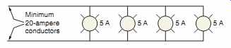
FIG. 1 Branch-circuit conductors shall have an ampacity not less than
the maximum load to be served, 210.19(A). See 210.23 for permissible loads.
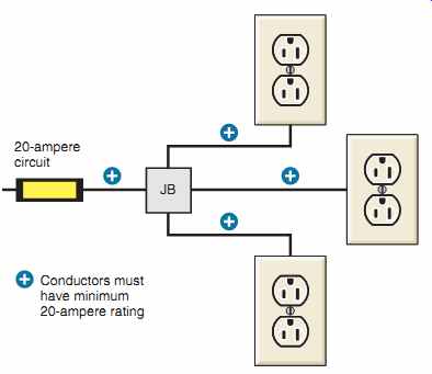
FIG. 2 All conductors in this circuit supplying receptacles shall have
an ampacity of not less than the rating of the branch circuit.
In this example, 20-ampere conductors must be used; see NEC 210.19(A)(2) and Table 210.24.
Conductor Sizing
The diameter of wire is usually given in a unit called a mil. A mil is defined as one-thousandth of an inch (0.001 inch). Mils squared are known as circular mils.
Table 8 in Section 9 of the NEC clearly shows that conductors are expressed in AWG numbers from 18 (1620 circular mils) through 4/0 (211,600 circular mils). Wire sizes larger than 4/0 are expressed in circular mils.
Large conductors, such as 500,000 circular mils, are generally expressed as 500 kcmil. Because the letter "k" designates 1000, the term kcmil means "thousand circular mils." This is much easier to express in both written and verbal terms.
Table 2 Allowable ampacities flexible cords.
Older texts used the term MCM, which also means "thousand circular mils." The first letter "M" refers to the Roman numeral that represents 1000. Thus, 500 MCM means the same as 500 kcmil.
Roman numerals are no longer used in the electrical industry for expressing conductor sizes.
Overcurrent Protection for Conductors
Conductors must be protected against overcurrent by fuses or circuit breakers rated not more than the ampacity of the conductors, NEC 240.4.
NEC 240.4(B) permits the use of the next higher standard overcurrent device rating, as shown in 240.6(A). This permission is granted only when the overcurrent device is rated 800 amperes or less.
For example, from Table 310.15(B)(16), a 6 AWG conductor with Type THWN insulation rated for 75°C has an allowable ampacity of 65 amperes.
In 240.6(A), we find that the next higher standard rating for an overcurrent device is 70 amperes.
Nonstandard ampere ratings of fuses and breakers are also permitted.
NEC 240.4(D) spells out the maximum overcurrent protection for small branch-circuit conductors.
Table 3 illustrates the requirements of 240.4(D).
There are exceptions for motor branch circuits and HVAC equipment. Motor circuits are discussed in Section 19 and Section 22. HVAC circuits are discussed in Section 23.
Table 3 Maximum overcurrent protection for 14, 12, and 10 AWG copper conductors.
Branch-Circuit Rating
The rating of the overcurrent device (OCD) determines the rating of a branch circuit, as shown in FIG. 3.
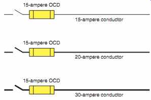
FIG. 3 All three of these branch circuits are rated as 15-ampere circuits,
even though larger conductors were used for some other reason, such as solving
a voltage-drop problem. The rating of the overcurrent device (OCD) determines
the rating of a branch circuit, 210.3.
PERMISSIBLE LOADS ON BRANCH CIRCUITS (210.23)
The NEC is very specific about the loads permitted on branch circuits. Here is a recap of these requirements.
• The load shall not exceed the branch-circuit rating.
• The branch circuit must be rated 15, 20, 30, 40, or 50 amperes when serving two or more out lets, NEC 210.3.
• An individual branch circuit may supply any size load.
• 15- and 20-ampere branch circuits
a. may supply lighting, other equipment, or both types of loads.
b. for cord-and-plug-connected equipment, shall not exceed 80% of the branch-circuit rating.
c. for equipment fastened in place, shall not exceed 50% of the branch-circuit rating if the branch circuit also supplies lighting, other cord-and-plug-connected equipment, or both types of loads.
• The 20-ampere small-appliance circuits in homes shall not supply other loads, NEC 210.11(C)(1).
• 30-ampere branch circuits may supply equipment such as dryers, cooktops, water heaters, and so forth. Cord-and-plug-connected equipment shall not exceed 80% of the branch-circuit rating.
• 40- and 50-ampere branch circuits may supply cooking equipment that is fastened in place, such as an electric range, as well as HVAC equipment.
• Over 50-ampere-rated branch circuits are for electric furnaces, large heat pumps, air-conditioning equipment, large double ovens, and similar large loads.
ALUMINUM CONDUCTORS
The conductivity of aluminum is not as great as that of copper for a given size. For example, checking Table 310.15(B)(16), an 8 AWG Type THHN copper conductor has an allowable ampacity of 55 amperes.
An 8 AWG Type THHN aluminum or copper-clad aluminum conductor has an ampacity of 45 amperes.
In 240.4(D), the maximum overcurrent protection for a 12 AWG copper conductor is 20 amperes but only 15 amperes for a 12 AWG aluminum or copper-clad aluminum conductor.
Aluminum conductors have a higher resistance compared to a copper conductor of the same size.
When considering voltage drop, a conductor's resistance is a key ingredient. Voltage-drop calculations are discussed later on in this Section.
Common Connection Problems Some common problems associated with aluminum conductors when not properly connected may be summarized as follows:
• A corrosive action is set up when dissimilar wires come in contact with one another when moisture is present.
• The surface of aluminum oxidizes as soon as it is exposed to air. If this oxidized surface is not penetrated, a poor connection results. When installing aluminum conductors, particularly in large sizes, an inhibitor (antioxidant) is brushed onto the aluminum conductor, and then the conductor is scraped with a stiff brush where the connection is to be made. The process of scraping the conductor breaks through the oxidation, and the inhibitor keeps the air from coming into contact with the conductor. Thus, further oxidation is prevented. Aluminum connectors of the compression type usually have an inhibitor paste already factory installed inside of the connector.
• Aluminum wire expands and contracts to a greater degree than does copper wire for an equal load. This is referred to as creep or cold flow.
This factor is another possible cause of a poor connection. Crimp connectors for aluminum conductors are usually longer than those for comparable copper conductors, thus resulting in greater contact surface of the conductor in the connector.
• Older technology aluminum such as Alloy 1350 experienced the above problems.
The newer technology aluminum such as AA-8000 has much better conductivity, creep resistance, and strength. Still, extreme care must be taken when terminating aluminum conductors. The manufacturer of the aluminum conductor or connector will provide detailed installation instructions.
Proper Installation Procedures
Proper, trouble-free connections for aluminum conductors require terminals, lugs, and/or connectors that are suitable for the type of conductor being installed.
Terminals on receptacles and switches must be suitable for the conductors being attached.
Table 4 shows how the electrician can identify these terminals. Listed connectors provide proper connection when properly installed. See NEC 110.14, 404.14(C), and 406.2(C).
Electrical Fires Caused by Improper Connections of Aluminum Conductors
Many electrical fires have been caused by improper connections and terminations of aluminum conductors. Most often, the problem is not the aluminum conductors. The problem is with the connections and terminations.
Many of these problems occurred in the meter base and at the main panel where aluminum service entrance conductors were installed years ago. In the course of time, the connections failed. Troubles also happened where aluminum conductors were terminated on receptacles and switches.
The Consumer Product Safety Commission (CPSC) (Washington, DC, 20207) publishes an excellent free booklet (#516) entitled Repairing Aluminum Wiring that explains what you can do with connections and terminations for the small aluminum wires that were installed years ago for the branch-circuit wiring of receptacles and switches.
The CPSC states that older homes wired with aluminum conductors are 55 times more likely to have one or more connections that will reach "Fire Hazard Conditions" than are homes wired with copper.
Table 4 Terminal identification markings and the acceptable types of conductors permitted to be connected to a specific type of terminal.
Although the NEC, notably in 110.5, 110.14, 240.4(D), 310.106(B), Table 310.15(B)(16), and other sections, recognizes aluminum conductors in sizes 12 AWG and larger, there are some local electrical codes that do not allow aluminum conductors to be used in branch-circuit sizes. Check this out before using aluminum conductors.
Some of the signs of potential problems might be
• wall switches and receptacles that feel warm to the touch.
• the smell of burning plastic or rubber at switches, receptacle, main panel, or meter.
• flickering lights.
• lights getting bright or dim.
• circuits that don't work; some circuits are on, others are off.
• TV shifting to another channel for no apparent reason.
• appliances with electronic controls shutting off or changing settings for no apparent reason.
• security system sounding off for no apparent reason.
Wire Connections
Wire connectors are known in the trade by such names as screw terminal, pressure terminal connector, wire connector, Wing-Nut, Wire-Nut, Scotchlok, Twister, split-bolt connector, pressure cable connector, solderless lug, soldering lug, solder lug, and others.
All cartons and manufacturers' literature show the size, number, and types of conductors permitted.
Solder-type lugs and connectors are rarely, if ever, used today. In fact, connections that depend on solder are not permitted for connecting ser vice-entrance conductors to service equipment, 230.81. Nor is solder permitted for grounding and bonding connections, 250.8. The labor costs and time spent make the use of the solder-type connections prohibitive.
Solderless connectors designed to establish Code-compliant electrical connections are shown in FIG. 4.
As with the terminals on wiring devices (switches and receptacles), wire connectors must be marked " AL" when they are to be used with aluminum conductors. This marking is found on the connector itself, or it appears on or in the shipping carton.
Connectors marked "AL/CU" are suitable for use with aluminum, copper, or copper-clad aluminum conductors. This marking is found on the connector itself, or it appears on or in the shipping carton.
Connectors not marked " AL" or "AL/CU" are for use with copper conductors only.
Unless specially stated on or in the shipping carton, or on the connector itself, conductors made of copper, aluminum, or copper-clad aluminum may not be used in combination in the same connector.
When combinations are permitted, the connector will be identified for the purpose and for the conditions when and where they may be used. The conditions usually are limited to dry locations only.
There are some "twist-on" wire connectors that have recently been listed for use with combinations of copper and aluminum conductors.
The preceding data are found in 110.14 and in the Underwriters Laboratories (UL) Standards.
When terminating large conductors such as service entrance conductors, be sure to read any instructions that might be included with the equipment where these conductors will be terminated. Terminations for all electrical connections to devices and equipment shall be tightened to the torque as required by the manufacturer of such electrical device or equipment, 110.12(D).
Old Houses Wired with Aluminum Conductors
If you come across a house wired with aluminum conductors, it was probably wired back in the mid-sixties or early seventies. You will very likely find problems where the conductors are terminated on switches and receptacles. Take special care when changing out switches and receptacles or making splices. Use wiring devices that bear the AL/ CU marking. You can also use special "pigtails" designed to make the connection between aluminum and copper conductors and terminals. One such connector is COPALUM-a compression (crimp) connector. Apply an antioxidant to the splice or connection as recommended by the manufacturer of the connector.
==========
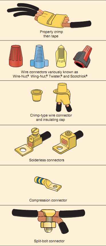
FIG. 4 Types of wire connectors.
Crimp connectors used to splice and terminate 20 AWG to 500 kcmil aluminum-to-aluminum, aluminum-to-copper, or copper-to-copper conductors.
Connectors used to connect wires together on combinations of 18 AWG through 6 AWG conductors.
They are twist-on, solderless, and tapeless.
*Wire-Nut, ® Wing-Nut, ® and Twister ® are registered trademarks of Ideal Industries, Inc. Scotchlok® is a registered trademark of 3M.
Connectors used to connect wires together in combinations of 16, 14, and 12 AWG conductors.
They are crimped on with a special tool, then covered with a snap-on insulating cap.
Solderless connectors are available in sizes 4 AWG through 500 kcmil conductors. They are used for one solid or one stranded conductor only, unless otherwise noted on the connector or on its shipping carton. The screw may be of the standard screwdriver slot type, or it may be for use with an allen wrench or socket wrench. Compression connectors are used for 8 AWG through 1000 kcmil conductors. The wire is inserted into the end of the connector, then crimped on with a special compression tool. Split-bolt connectors are used for connecting two conductors together, or for tapping one conductor to another. They are available in sizes 10 AWG through 1000 kcmil. They are used for two solid and/or two stranded conductors only, unless otherwise noted on the connector or on its shipping carton.
==========
CONDUCTOR INSULATION
The NEC requires generally that all conductors be insulated, 310.106(D). There are a few exceptions, such as the permission to use a bare neutral conductor for services, and bare equipment grounding conductors.
NEC Table 310.104(A) shows many types of conductors, their applications, and insulations. The conductors most commonly used fall into the thermoplastic and thermoset categories.
Insulation. Table 310.15(B)(7) is a table of conductor ampacities that are greater than the ampacities found in Table 310.15(B)(16). This table is permit ted to be used only for dwelling unit 120/240-volt, 3-wire, single-phase service-entrance conductors, service-lateral conductors, and feeder conductors that serve as the main power feeder to a dwelling unit. This table is based on the tremendous known load diversity found in homes. These special ampacities must not be used for feeder conductors that do not serve as the main power feeder to a dwelling. An example of this would be the feeder from the Main Panel A to Panel B in the residence discussed later on in this text.
Table 5 shows the special ampacities discussed previously. This table is the same as Table 310.15(B)(7) in the NEC.
The insulation covering wires and cables used in house wiring is usually rated at 600 volts or less.
Exceptions to this statement are low-voltage wiring and luminaire wiring.
What Is Thermoplastic Insulation?
==========
Table 5 Special ampacity ratings for residential 120/240-volt, 3-wire, single-phase service-entrance conductors, service-lateral conductors, and feeder conductors that serve as the main power feeder to a dwelling unit.
Notes: Where the conductors will be exposed to temperatures in excess of 86°F (30°C), apply the correction factors found in Table 310.15(B)(2)(a).
Conductors having a suffix "2," such as THWN-2, are permitted for continuous use at 90°C in wet or dry locations. Though these conductors cannot be used at their 90°C ampacities, the higher ampacities can be used for derating for elevated temperatures or for more than three current-carrying conductors installed without maintaining spacing.
==========
Thermoplastic insulation is the most common.
It is like chocolate. It will soften and melt if heated above its rated temperature. It can be heated, melted, and reshaped. Thermoplastic insulation will stiffen at temperatures colder than 14°F (210°C). Typical examples of thermoplastic insulation are Types THHN, THHW, THW, THWN, and TW.
What Is Thermoset Insulation? Thermoset insulation can withstand higher and lower temperatures. It is like baking a cake. Once the ingredients have been mixed, heated, and formed, it can never be reheated and reshaped. If heated above its rated temperature, it will char and crack. Typical examples of thermoset insulation are Types RHH, RHW, XHH, and XHHW.
Table 310.104(A) lists the various conductor insulations and their applications.
The allowable ampacities of copper conductors are given in Table 310.15(B)(16) for various types of Older Types of Conductor Insulation
Although Type THHN/THWN is the most common building wire used today, older types of conductor insulation might still be found, such as Types A, RH, RU, RUH, RUW, T, TW, and THW. Some of these are still shown in the NEC but may no longer be manufactured. Some are still manufactured but are difficult, if not impossible, to find at an electrical supply house.
Others are available only as a special-order product.
Table 6 Typical conductors used for residential wiring.
WET, DAMP, DRY, AND SUNLIGHT LOCATIONS
Conductors are listed for specific locations. Be sure that the conductor you use is suitable for the location. Table 6 shows some of the more typical conductors used in house wiring. Here are some definitions taken directly from the NEC:
• Damp Location. Locations protected from weather and not subject to saturation with water or other liquids, but subject to moderate degrees of moisture. Examples of such locations include partially protected locations under canopies, marquees, roofed open porches, and like locations; and interior locations subject to moderate degrees of moisture, such as some basements, some barns, and some cold-storage warehouses.*
• Dry Location. A location not normally subject to dampness or wetness. A location classified as dry may be temporarily subject to dampness or wetness, as in the case of a building under construction.*
• Wet Location. Installations underground or in concrete slabs or masonry in direct contact with the earth; in locations subject to saturation with water or other liquids, such as vehicle washing areas; and in unprotected locations exposed to weather.* The interior of raceways installed in wet locations is considered a wet location. Insulated conductors and cables in these locations shall be listed for wet locations. See NEC 300.5(B), 300.9, and 310.10(C).
• Locations Exposed to Direct Sunlight. Insulated conductors and cables used where exposed to direct rays of the sun shall be listed, or listed and marked as being "sunlight resistant." See NEC 310.10(D), 310.15(A)(3), 310.104, and Table 310.104(A) for additional information.
Conductor Insulation Temperature Ratings
Conductors are also rated as to the temperature their insulation system can withstand. Even though the NEC provides Fahrenheit temperatures for conductors, they are not used by the electrical industry.
Only the Celsius temperatures are used in referring to the temperature rating of insulation. The tempera ture rating of conductor insulations commonly used in residential wiring is:
Celsius | Fahrenheit
Type TW 60° 140°
Type THWN 75° 167°
Type THHN 90° 194°
Without question, conductors with Type THHN/ THWN insulation are the most popular and most commonly used, particularly in the smaller sizes, because of their small diameter (easy to handle; more conductors of a given size permitted in a given size raceway) and their suitability for installation where high temperatures are encountered, such as attics, buried in insulation, and supplying recessed fixtures.
The temperature rating of nonmetallic-sheathed cable is 90°C. However, NEC 334.80 states that the allowable ampacity is that of the 60°C column in Table 310.15(B)(16). The 90°C ampacity is permit ted to be used for derating purposes.
Multiple-Type Designations
Some conductors are listed for more than one application. For example, a conductor marked THHN/THWN is rated 600 volts, 90°C when used in dry locations, and 600 volts, 75°C when used in wet locations. As always, read the surface marking on the conductor insulation, on the tag, on the reel, or on the carton. The NEC covers Conductors for General Wiring in Article 310.
The Weakest Link of the Chain
A conductor has two ends! Selecting a conductor ampacity based solely on the allowable ampacity values found in Table 310.15(B)(16) is a very common mistake that can prove costly.
In any given circuit, we have an assortment of electrical components that have different maximum temperature ratings. Our job is to find out which component is the "weakest link" in the system and do our circuit design based on the lowest rated component in the circuit. Maximum temperature ratings are found in the NEC and in the UL Standards.
• Circuit breakers: UL 489. Generally marked "75°C Only" or "60°C/75°C."
• Conductors: Table 310.104(A), Table 310.15(B)(16), and UL 83.
• Disconnect switches: UL 98. Generally marked "75°C Only" or "60°C/75°C."
• Panelboards: UL 67. Panelboards are generally marked 75°C. The temperature rating of a panelboard has been established as an assembly with circuit breakers in place. Do not use the circuit breakers' temperature marking by itself.
It is the temperature marking on the assembly that counts.
• Receptacles and attachment-plug caps: UL 498. Most 15- and 20-ampere branch circuits have receptacles that are marked with a wire size and not a temperature rating. As a result, the default temperature rating in NEC 110.14(C) applies. This results in a maximum temperature rating of 60°C. Some 30-ampere receptacles are rated 60°C and some are rated for 75°C. Larger 50-ampere receptacles are rated 75°C. You will want to verify the marking on the device.
• Snap switches: The safety standard is UL 20. Most 15- and 20-ampere branch circuits have snap switches with a maximum terminal temperature rating of 60°C.
• Wire splicing devices and connectors: Wire Nuts, Wing-Nuts, Twisters, and Scotchloks for copper conductors (UL 486) and for aluminum conductors (UL 486B). These types of connectors are commonly rated 105°C.
Table 7 indicates the correct applications for conductors and terminations.
Another key NEC requirement is found in 110.14(C), "Termination Limitations," where we find the following:
For circuits rated 100 amperes or less, or marked for conductor sizes 14 through 1 AWG, unless otherwise identified, the terminals on wiring devices, switches, breakers, motor controllers, and other electrical equipment are based on the ampacity of 60°C conductors. It is acceptable to install conductors having a higher temperature rating, such as 90°C THHN, but you must use the 60°C ampacity values.
Table 7 Types of conductor temperature ratings permitted for various terminal temperature ratings in conformance to the NEC and the UL Standards.
For circuits rated over 100 amperes, or marked for conductors larger than 1 AWG, the conductors installed must have a minimum 75°C rating. The ampacity of the conductors is based on the 75°C values. It is acceptable to install conductors having a higher temperature rating, such as 90°C THHN, but you must use the 75°C ampacity values.
When using high-temperature insulated conductors where adjustment factors are to be applied, such as derating for more than three
current-carrying conductors in a raceway or cable, or correcting where high temperatures are encountered, the final results of these adjustments (in amperes) must comply with the requirements of 110.14(C). Similar requirements are found in the UL Standards.
Examples of applying derating factors and correcting factors are found in Section 18.
Temperature ratings of conductors and cables are discussed later in this Section.
In 240.4(D), there is a built-in code compliance limitation for applying small branch-circuit conductors. Here we find that the maximum overcurrent protection is 15 amperes for 14 AWG, 20 amperes for 12 AWG, and 30 amperes for 10 AWG.
From Table 310.15(B)(16) we find that:
• 14 AWG copper conductors' allowable ampacity is 15 amperes in the 60°C column 20 amperes in the 75°C column 25 amperes in the 90°C column
• 12 AWG copper conductors' allowable ampacity is 20 amperes in the 60°C column 25 amperes in the 75°C column 30 amperes in the 90°C column
• 10 AWG copper conductors' allowable ampacity is 30 amperes in the 60°C column 35 amperes in the 75°C column 40 amperes in the 90°C column There are exceptions to this maximum overcurrent protection rule for motor, air-conditioner, and heat pump branch circuits. These exceptions are covered elsewhere in this text.
In summary, we cannot arbitrarily use the ampacity values for conductors as found in Table 310.15(B)(16). Conductor ampacity is not a "stand alone" issue. We must also consider the temperature limitations of the equipment, such as panelboards, receptacles, snap switches, receptacles, connectors, and so on. The lowest maximum temperature-rated device in an electrical system is the weakest link, and it is the weakest link on which we must base our ultimate conductor ampacity and conductor insulation decision.
Knob-and-Tube Wiring
Older homes were wired with open, individual, insulated conductors supported by porcelain knobs and tubes. In its day, knob-and-tube wiring served its purpose well. This text does not cover knob-and tube wiring because this method is no longer used in new construction. On occasion, it is necessary to make some modifications to knob-and-tube wiring when doing remodel work. The NEC covers this wiring method in Article 394.
Watch out when working on old knob-and-tube wiring. You will possibly find the old rubber insulation on the conductors dried out and brittle from the many years of heat generated by luminaires and from the extreme heat in attics, particularly when the conductors are completely buried in thermal insulation. The conductor insulation might fall apart when touched or moved. This is a potential fire hazard! If you do find this situation, one fix is to slide insulation (heat shrink) tubing (available from electrical distributors) over the conductors to re-insulate them.
FIG. 5 is a photo of typical knob-and-tube wiring from the 1930s.
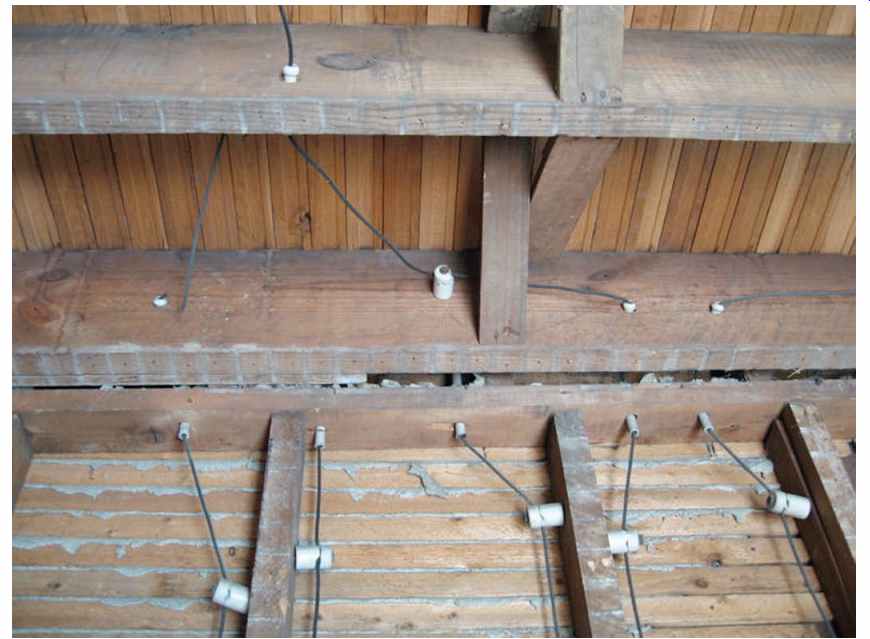
FIG. 5 Photograph of a typical knob-and-tube wiring from the 1930s.
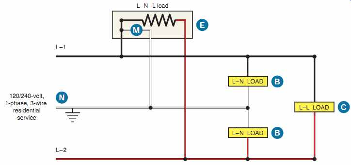
FIG. 6 Diagram showing line-to-line and line-to-neutral loads.
Neutral Conductor Size
FIG. 6 shows how line-to-line loads and line to-neutral loads are connected. The grounded neutral (white) conductor for residential services and feeders is permitted to be smaller than the "hot" ungrounded phase (black, red) conductors L1 and L2 only when the neutral conductor is properly and adequately sized to carry the maximum unbalance loads calculated according to NEC 215.2, 220.61, and 230.42.
NEC 215.2 relates to feeders and refers us to Article 220 for calculation requirements.
NEC 230.42 relates to services and refers us to Article 220 for calculation requirements.
Focusing on the neutral conductor, 220.61 states that the feeder or service neutral load shall be the maximum unbalance of the load determined by this Article.
NEC 220.61 further states that the maximum unbalanced load shall be the maximum net calculated load between the neutral and any one ungrounded conductor.
In a typical residence, we find a number of loads that carry little or no neutral current, such as an electric water heater, electric clothes dryer, electric oven and range, electric furnace, and air conditioner.
Checking FIG. 6, you can readily see that load (C) is connected to a straight 240-volt, 2-wire circuit and has no neutral current. Note that load (E) is connected to a 120/240-volt 3-wire circuit, and in this hookup the120-volt motor (M) will result in current flowing in the neutral conductor. Loads (B) are 120-volt loads that are connected line to neutral.
Thus we find logic in the NEC, which permits reducing the neutral conductor size on services and feeders where the calculations prove that the neutral conductor will be carrying less current than the "hot" phase conductors.
See Section 20 for sizing neutral conductors for electric range branch circuits and Section 29 for sizing neutral service-entrance conductors.
VOLTAGE DROP
Low voltage can cause lights to dim, some television pictures to "shrink," motors to run hot, electric heaters to not produce their rated heat output, and appliances to not operate properly.
Low voltage in a home can be caused by
• wire that is too small for the load being served.
• a circuit that is too long.
• poor connections at the terminals.
• conductors operating at high temperatures having higher resistance than when operating at lower temperatures.
A simple formula for calculating voltage drop on single-phase systems considers only the dc resistance of the conductors and the temperature of the conductor. See Table 8, Section 9, in the NEC for the dc resistance values. The more accurate formulas consider ac resistance, reactance, temperature, spacing, in metal conduit and in nonmetallic conduit, NEC Table 9, Section 9. Voltage drop is covered in great detail in Electrical Wiring-Commercial. The simple voltage-drop formula is more accurate with smaller conductors and gets increasingly less accurate as conductor size increases. It is sufficiently accurate for voltage-drop calculations necessary for residential wiring.
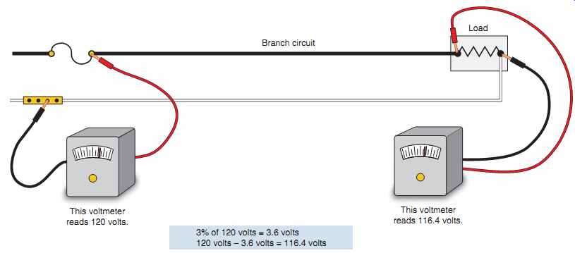
FIG. 7 Maximum recommended voltage drop on a branch circuit is 3%, 210.19(A),
Informational Note No. 4.
To Find Voltage Drop in a Single-Phase Circuit
Ed = K x I x L x 2 / CMA
To Find Conductor Size for a Single-Phase Circuit
CMA = Kx I x Lx 2 / Ed
In the above formulae:
Ed = result of voltage drop calculation in volts.
K = approximate resistance in ohms per circular-mil foot at 75°C.
• For uncoated copper wire, use 12 ohms.
• For aluminum wire, use 20 ohms.
I = current in amperes flowing through the conductors.
L = length in feet from beginning of circuit to the load.
CMA = cross-sectional area of the conductors in circular mils.**
We use the factor of 2 for single-phase circuits because there is voltage drop in both conductors to and from the connected load.
To Find Voltage Drop and Conductor Size for a 3-Phase Circuit
Although residential wiring does not commonly use 3-phase systems, commercial and industrial systems do. To make voltage-drop and conductor sizing calculations for a 3-phase sys tem, substitute the factor of 1.732 (the square root of 3) in place of the factor 2 in the voltage-drop formulae.
Code References to Voltage Drop For branch circuits, refer to NEC 210.19(A),
Informational Note No. 4. The recommended maxi mum voltage drop is 3%, as shown in FIG. 7.
For feeders, refer to NEC 215.2(A), Informational Note No. 2. The recommended maximum voltage drop is 3%. See FIG. 8.
When both branch circuits and feeders are involved, the total voltage drop should not exceed 5%. This is shown in FIG. 8.
According to NEC 90.5(C), Informational Notes are explanatory only and are not to be enforced as Code requirement.
There is nothing in the NEC that dictates what the incoming voltage to a home must be. Incoming voltage is really determined by the electric utility and is affected by the type, size, and length of the ser vice conductors, transformer(s), and primary lines.
Electric utilities come under the jurisdiction of the National Electrical Safety Code (NESC). A local public service commission, usually at the state level, mandates maximum over- and undervoltages. This is generally within the 5% range of nominal voltage.
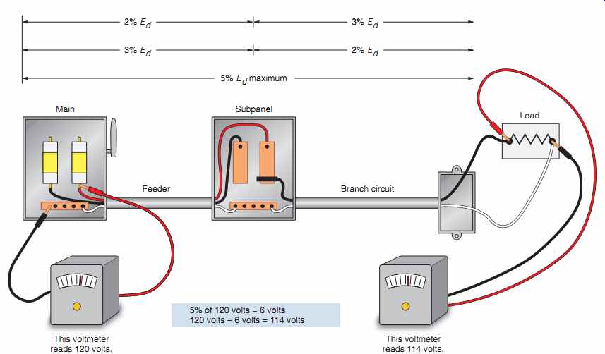
FIG. 8 NEC 210.19(A), Informational Note No. 4, and 215.2(A), Informational
Note No. 2, of the Code state that the total voltage drop from the beginning
of a feeder to the farthest outlet on a branch circuit that does not exceed
5% will provide reasonable efficiency of operation. In this figure, if the
voltage drop in the feeder is 3%, then do not exceed 2% voltage drop in the
branch circuit. If the voltage drop in the feeder is 2%, then do not exceed
3% voltage drop in the branch circuit.
Table 8 Circular mil area for many of the more common conductors.
A Word of Caution When Using High-Temperature Conductors
Note in NEC Table 310.15(B)(16) that conductor insulations fall into three classes of temperature ratings: 60°C, 75°C, and 90°C. For a given conductor size, we find that the allowable ampacity of a 90°C insulated conductor is greater than that of a 60°C insulated conductor. Therefore, be careful when selecting conductors based on their ability to withstand high temperatures. For example:
• 8 AWG THHN (90°C) copper has an allowable ampacity of 55 amperes.
• 8 AWG THW (75°C) copper has an allowable ampacity of 50 amperes.
• 8 AWG TW (60°C) copper has an allowable ampacity of 40 amperes.
We learned earlier in this Section that according to 110.14(C), we use the 60°C column of NEC Table 310.15(B)(16) for circuits rated 100 amperes or less, and the 75°C column for circuits rated over 100 amperes. However, when the equipment is marked as being suitable for 75°C, we can take advantage of the higher ampacity of 75°C conductors. This oftentimes results in a smaller size conductor and a correspondingly smaller raceway.
But installing smaller conductors might result in excessive voltage drop.
Therefore, after selecting the proper size conductor for a given load, it is always a good idea to run a voltage-drop calculation to make sure the volt age drop is not excessive.
What Is the Advantage of High-Temperature Conductors? They can withstand the high temperatures found in attics and high-temperature climates.
Another big advantage of the higher ampacities of high-temperature insulation is that the NEC permits the higher ampacity values to be used as the starting point when applying derating and correcting factors. Example calculations of this are found in Section 18.
Section 19 has more information on the effect voltage differences have on wattage output of appliances and on electric motors.
APPROXIMATE CONDUCTOR SIZE RELATIONSHIP
There is a definite relationship between the circular mil area and the resistance of conductors. The following rules explain this relationship.
Rule One. For wire sizes up through 0000, every third size doubles or halves in circular mil area.
Thus, a 1 AWG conductor is 2 times larger than a 4 AWG conductor (83,690 versus 41,470). Thus, a 0 wire is one-half the size of 0000 wire (105,600 versus 211,600).
Rule Two. For wire sizes up through 0000, every consecutive wire size is approximately 1.26 times larger or smaller than the preceding wire size.
Thus, a 3 AWG conductor is approximately 1.26 times larger than a 4 AWG conductor (41,740 x 1.26 5 52,592). A 2 AWG conductor is approximately 1.26 times smaller than a 1 AWG conductor (83,690 4 1.26 5 66,420).
Try to fix in your mind that a 10 AWG conductor has a cross-sectional area of 10,380 circular mils and that it has a resistance of 1.2 ohms per 1000 ft (300 m). The resistance of aluminum wire is approximately 2 ohms per 1000 ft (300 m). By remembering these numbers, you will be able to per form voltage-drop calculations without having the wire tables readily available.
EXAMPLE
What is the approximate cross-sectional area, in circular mils, and resistance of a 6 AWG copper conductor?
Solution: Note in Table 9 that when the CMA of a wire is doubled, then its resistance is cut in half.
Inversely, when a given wire size is reduced to one half, its resistance doubles.
Table 9 "Every third size" and the 1.26 relationship between the circular-mil area (CMA) and the resistance in ohms per 1000 ft of copper conductors sizes 10 AWG through 6 AWG.
NONMETALLIC SHEATHED CABLE (ARTICLE 334 )
The NEC and UL Standard 719 describe the construction details of nonmetallic-sheathed cable. The following is a summary of these details.
Description Most electricians still refer to nonmetallic sheathed cable as Romex, a name chosen years ago by the Rome Wire and Cable Company. Romex is now a registered trademark of Southwire Company.
Nonmetallic-sheathed cable is a factory assembly of two or more insulated conductors having an outer sheath of moisture-resistant, flame-retardant, nonmetallic material. This cable is available with two or three current-carrying conductors. The conductors range in size from 14 AWG through 2 AWG for cop per conductors, and from 12 AWG through 2 AWG for aluminum or copper-clad aluminum conductors.
Two-wire cables contain one black conductor, one white conductor, and one bare equipment grounding conductor. Three-wire cables contain one black, one white, one red, and one bare equipment grounding conductor. Equipment grounding conductors are per mitted to have green insulation, but bare equipment grounding conductors are the most common.
NEC 334.108 requires that nonmetallic-sheathed cable have an insulated or a bare equipment grounding conductor.
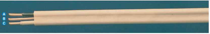
FIG. 9 A nonmetallic-sheathed Type NM-B cable showing (A) black "ungrounded" (hot)
conductor, (B) bare equipment "grounding" conductor, and (C) white "grounded" conductor.
(Southwire Company)
FIG. 9 clearly shows a bare equipment grounding conductor. Sometimes the bare equipment grounding conductor is wrapped with paper or fiberglass, which acts as a filler. The equipment grounding conductor is not permitted to be used as a current-carrying conductor.
Types of Nonmetallic-Sheathed Cable UL 719 lists two types of nonmetallic-sheathed cable. The NEC shows three types of nonmetallic sheathed cable.
• Type NM-B is the most common type of non metallic-sheathed cable in use today. Type NM-B cable has a flame-retardant, moisture-resistant, nonmetallic outer jacket. The conductors are rated 90°C. The ampacity is based on the 60°C column in NEC Table 310.15(B)(16). The conductors in Type NM-B meet all of the requirements of THHN but do not have the identifying marking along the entire length of the individual conductors. In the past, Type NM cable contained conductors having Type TW insulation.
• Type NMC-B cable has a flame-retardant, moisture-resistant, fungus-resistant, and corrosion resistant, nonmetallic outer jacket. The conductors are rated 90°C. The ampacity is based on the 60°C column in NEC Table 310.15(B)(16). Type NMC-B cable is not commercially available.
Underground feeder Type UF-B cable can be used as a substitute for NMC.
• Type NMS-B cable is a hybrid cable that contains the conventional insulated power conductors as well as telephone, coaxial, home entertainment, and signaling conductors all in one cable. This type of cable is used for home automation systems using the latest in digital technology.
Prior to the 2008 NEC, Article 780 recognized this wiring method for closed loop and programmed power distribution. In the 2008 NEC, Article 780 was deleted. The Type NMS-B cable had a moisture-resistant, flame-retardant, nonmetallic outer jacket. Type NMS-B cable is not commercially available. This type of home automation never did take off. It fell by the wayside. Today, we are seeing a tremendous amount of wireless home automation systems.
Although somewhat confusing, the UL standards use the suffix B, whereas the NEC refers to nonmetallic-sheathed cables as Type NM, NMC, and NMS. The conductors in these cables are rated 90°C. Types NM, NMC, and NMS cable, identified by the markings NM-B, NMC-B, and NMS-B, meet this 90°C requirement. See 334.112.
As of the writing of this edition of Electrical Wiring-Residential, there are no UL listings for Type NMS and NMS-B cables.
Why the Suffix B ?
The suffix B means that the conductors have 90°C insulation.
Older nonmetallic-sheathed cable contained 60°C-rated conductors. There were many problems with the insulation becoming brittle and breaking off due to the extremely high temperatures associated with recessed and surface-mounted luminaires: fires resulted. In hot attics, after applying correction factors, the adjusted allowable ampacity of the conductors could very well be zero. To solve this dilemma, since December 17, 1984, UL has required that the conductors be rated 90°C, and that the cable be identified with the suffix B. This suffix makes it easy to differentiate the newer 90°C from the old 60°C cable.
The ampacity of the conductors in nonmetallic sheathed cable is based on that of 60°C conductors.
The 90°C ampacity is permitted to be used for derating purposes, such as might be necessary in attics.
The final derated ampacity must not exceed the ampacity for 60°C conductors. More specifics can be found in NEC 334.80.
Table 310.15(B)(16) shows the allowable ampacities for conductors.
Overcurrent Protection for Small Conductors
Overcurrent protection for small copper conductors, in conformance to 240.4(D), is as follows:
• 14 AWG 15 amperes
• 12 AWG 20 amperes
• 10 AWG 30 amperes
A typical nonmetallic-sheathed cable is illustrated in FIG. 9.
Color Coding of Type NM-B Jacket
To make installations easier for the electrician and identification of the conductor size easier for the electrical inspector, color-coded nonmetallic sheathed cable is available.
Conductor Size Color of Jacket
14 AWG White
12 AWG Yellow
10 AWG Orange
8 and 6 AWG Black
New Types of NM-B Cable
At least one manufacturer offers a 4-conductor Type NM-B that can be used for two branch circuits.
This cable is used where sharing of the neutral is not wanted, as in a multiwire branch circuit, or for branch circuits supplying GFCIs and AFCIs, where sharing the neutral is not permitted.
This cable contains the following:
• One bare equipment grounding conductor
• Pair 1: one black and one white
• Pair 2: one black and one white (with a red stripe)
Because all four conductors in this cable are current-carrying conductors, the ampacity of the conductors must be adjusted (derated) according to NEC 310.15(B)(3)(a).
Where Nonmetallic-Sheathed Cable May Be Used Table 10 shows the uses permitted for Types NM-B, NMC-B, and NMS-B.
Equipment Grounding Conductors (250.122) Equipment grounding conductor (EGC) sizing is based on the rating or setting of the overcurrent device protecting a given branch circuit or feeder.
See NEC Table 250.122.
The EGC in a nonmetallic-sheathed cable is sized according to NEC Table 250.122 and is usually bare. Table 11 is a short version of Table 250.122.
An EGC does not have to be larger than the ungrounded conductors of a given circuit. Why? Because in the event of a ground fault, the amount of ground-fault current returning on the EGC can never be more than the ground-fault current flowing on the ungrounded conductor of that circuit that caused the problem. It's a simple series circuit. What goes out-comes back! See NEC 250.122(A).
==============
Table 10 Uses permitted for nonmetallic-sheathed cable.
May be used on circuits of 600 volts or less May be run exposed or concealed in dry locations May be installed exposed or concealed in damp and moist locations Has flame-retardant and moisture-resistant outer covering Has fungus-resistant and corrosion-resistant outer covering May be used to wire one- and two-family dwellings or multifamily dwellings; see 334.10 May be embedded in masonry, concrete, plaster, adobe, fill May be installed or fished in the hollow voids of masonry blocks or tile walls where not exposed to excessive moisture or dampness May be installed or fished in the hollow voids of masonry blocks or tile walls where exposed to excessive moisture In outside walls of masonry block or tile In inside wall of masonry block or tile May be used as service-entrance cable Must be protected against physical damage May be run in shallow chase of masonry, concrete, or adobe if protected by a steel plate(s) at least 1/16 in. (1.6 mm) thick, then covered with plaster, adobe, or similar finish
==============
==============
Table 11 Minimum size equipment grounding conductors is based on the rating or setting of the overcurrent device protecting that particular branch circuit. This table is based on Table 250.122 of the NEC.
MINIMUM SIZE (AWG) EQUIPMENT GROUNDING CONDUCTOR
==============
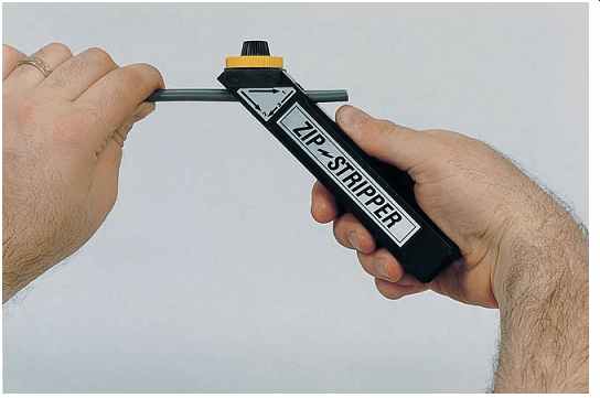
FIG. 10 This stripper is used to remove the outer jacket from nonmetallic-sheathed
cable. ( Seatek Co., Inc.)
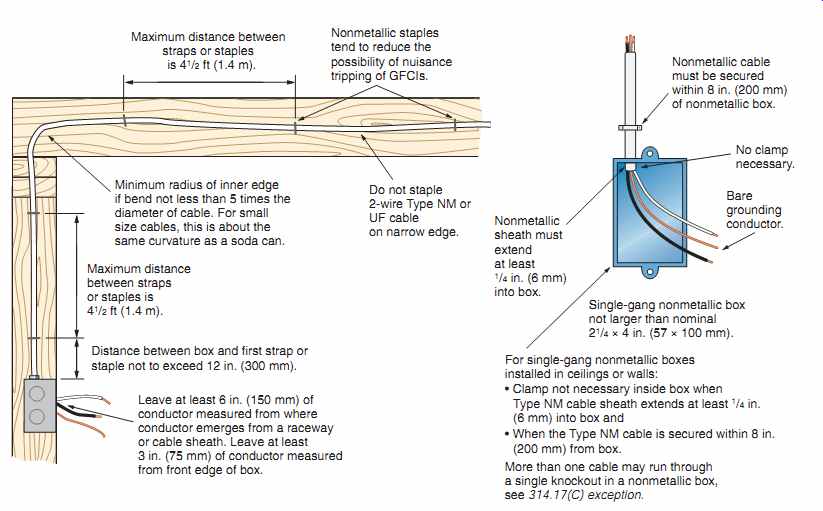
FIG. 11 Installation of nonmetallic-sheathed cable.
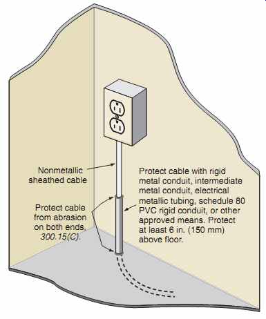
FIG. 12 Installation of exposed nonmetallic sheathed cable where passing
through a floor; see 334.15(B).
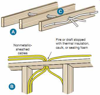
FIG. 13 The conductor ampacity in NM cables shall be adjusted according
to Table 310.15(B)(3)(a): (A) when NM cables are "bundled" or "stacked" for
distances more than 24 in. (600 mm) without maintaining spacing; or (B) when
more than two NM cables pass through wood framing members if sealed with thermal
insulation, caulk or sealing foam, and there is no spacing between the cables;
or (C) when more than two NM cables are installed in contact with thermal insulation.
See 310.15(B)(3)(a) and 334.80.
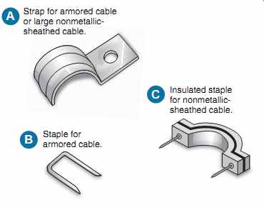
FIG. 14 (A) One-hole strap used for conduit, EMT, large nonmetallic sheathed
cable and armored cable.
(B) Metal staple for armored cable and nonmetallic-sheathed cable.
(C) Insulated staple for nonmetallic sheathed cable. Certain types of insulated and noninsulated staples can be applied with a staple gun.
FIG. 15 It is a Code violation to staple flat nonmetallic-sheathed cables on edge, 334.30.
====================
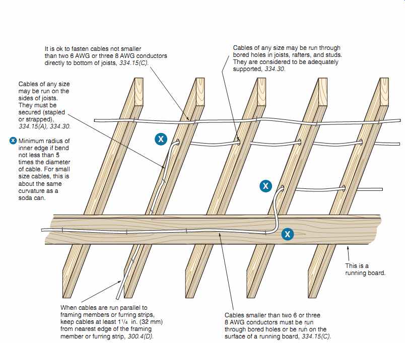
FIG. 16 The requirements for running nonmetallic-sheathed cable in unfinished
basements and crawl spaces.
It is ok to fasten cables not smaller than two 6 AWG or three 8 AWG conductors directly to bottom of joists, 334.15(C).
Cables of any size may be run through bored holes in joists, rafters, and studs. They are considered to be adequately supported, 334.30.
Cables of any size may be run on the sides of joists. They must be secured (stapled or strapped), 334.15(A), 334.30.
Minimum radius of inner edge if bend not less than 5 times the diameter of cable. For small size cables, this is about the same curvature as a soda can.
When cables are run parallel to framing members or furring strips, keep cables at least 1 1/4 in. (32 mm) from nearest edge of the framing member or furring strip, 300.4(D).
Cables of any size may be run through bored holes in joists, rafters, and studs. They are considered to be adequately supported, 334.30.
Cables smaller than two 6 or three 8 AWG conductors must be run through bored holes or be run on the surface of a running board, 334.15(C).
================
Prev. | Next
Similar Articles