AMAZON multi-meters discounts AMAZON oscilloscope discounts
With all of the techniques that are available for predictive maintenance, how do we select the best methods required to monitor the critical machines, equipment, and systems in a plant? It would be convenient if a single system existed that would provide all of the monitoring and analysis techniques required to routinely monitor every critical piece of equipment. Unfortunately, this is not the case.
Each of the predictive techniques discussed in the preceding section are highly specialized. Each has a group of systems vendors that promote their technique as the single solution to a plant's predictive maintenance needs. The result of this specialization is that no attempt has been made by predictive maintenance systems vendors to combine all of the different techniques into a single, total-plant system. Therefore, each plant must decide which combination of techniques and systems is required to implement its predictive maintenance program.
If a plant decides to use all of the available techniques, a total capital cost for instrumentation and systems can easily exceed $150,000. In most cases, this fact alone would prohibit implementing a program; however, the true costs would be much higher. To implement a program that includes all of the predictive maintenance techniques would require extensive staffing, training, and technical support. A minimum staff of at least five trained technicians and three highly trained engineers would be required to maintain this type of program. The annual costs for this operation would be extremely high. The actual labor and overhead costs will depend on the salaries and overhead rates of each plant, but the annual cost could easily exceed $500,000.
Because of the high capital and operating costs, this type of program would have to save more than 1 million dollars each year to justify its costs. Even though this type of savings is possible in larger plants, most small to medium-sized plants cannot justify including all of the available techniques in their predictive maintenance programs.
How do you decide which techniques will provide a cost-effective method of con trolling the maintenance activities in your plant? The answer lies in determining the type of plant equipment that needs to be monitored. Plants with a large population of electrical equipment (e.g., motors, transformers, switch gear) should use thermo graphic or infrared scanning as their primary tool, whereas plants with a large population of mechanical machines and systems should rely on vibration techniques. In most cases, your plant will require a combination of two or more techniques, but you may elect to establish one technique as an in-house tool and contract with an outside source for periodic monitoring using the secondary techniques. This approach would provide the benefits that the secondary techniques provide without the additional costs.
THE OPTIMUM PREDICTIVE MAINTENANCE PROGRAM
The optimum predictive maintenance program will, in most cases, consist of a combination of several monitoring techniques. Because most plants have large populations of mechanical systems, vibration techniques will be the primary method required to implement a total-plant program.
Predictive Technologies
Vibration methods alone cannot provide all of the information required to maintain the operating condition of the plant. It cannot provide the data required to maintain electrical equipment or the operating efficiency of nonmechanical equipment. There fore, secondary methods must be used to gain this additional information. At a minimum, a comprehensive predictive maintenance program should include:
- • Visual inspection
- • Process dynamics
- • Thermography
- • Tribology
Visual Inspection:
All predictive maintenance programs should include visual inspection as one of the tools used to monitor plant systems. The cost-considered in conjunction with other techniques that require periodic monitoring of plant equipment-is relatively small.
In most cases, visual inspection can take place as the predictive maintenance team conducts the regular data acquisition required by any of the other techniques and there fore adds little or no costs to the program. Visual inspection can provide a wealth of information about the operating condition of the plant. This simple but often neglected tool can detect leaks, loose mountings, structural cracks, and several other failure modes that can limit the plant's performance.
Most of the commercially available vibration-monitoring systems provide visual observation capabilities in their data acquisition instruments. Therefore, visual observations can automatically be recorded concurrent with data acquisition of vibration data.
Process Dynamics:
A true understanding of plant condition cannot be accomplished without knowing the operating efficiency of every machine or system in the plant. For example, how do you know the operating condition of a shell-and-tube heat exchanger without knowing the efficiency and fouling factor? The calculations required to determine these two critical factors is extremely simple, but you must first know the actual process parameters (i.e., flow, pressure and temperature) on both the primary and secondary side of the heat exchanger. Six simple measurements will provide the data required to periodically calculate both the efficiency and fouling factor.
Monitoring process parameters usually require the addition of some plant instrumentation. Few plants have working instruments that monitor all of the variables required to determine the operating condition of critical systems; however, advancements in instrumentation technology have developed nonintrusive methods of acquiring most of the required process variables without the expense of installing permanent instrumentation. Several techniques have been developed to monitor process flow- the most difficult process parameter to measure-without installing a pitot or vortex shedding flowmeter. These new instruments are commercially available and can often be read by the microprocessor-based, vibration-based predictive maintenance systems.
A few of the microprocessor-based, vibration-monitoring systems provide the ability to directly acquire process data from permanently installed instruments and allow for manual entry of analog gauges. This capability provides the means to automatically acquire process parameters in conjunction with routine acquisition of vibration data.
In addition, some of these systems can automatically calculate unknown process parameters (e.g., efficiency, fouling factors). These systems record the process parameters that can be directly measured and then automatically calculate, store, and trend the unknown in the same manner as parameters that are acquired directly. This ability greatly enhances the predictive maintenance system's benefits and eliminates both the manual effort required to calculate unknowns and the potential errors that manual calculation may create.
Thermography:
Implementing a full thermographic program is usually not cost effective; however, many of the vibration-based systems will permit direct acquisition of infrared data through a point-of-use scanner. This feature should be incorporated into every predictive maintenance program. The scanner can be used to acquire several process parameters that will augment the program. Typical applications for this technique include bearing cap temperatures, spot checks of process temperatures, motor winding temperatures, spot checks of electrical equipment, and many more.
Unless the plant has a large population of electrical equipment or heat transfer systems, the cost of implementing a full infrared scanning system is prohibitive. For plants that have less of this type of equipment or systems, the most cost-effective method of including the benefits of full infrared scanning is to purchase periodic surveys of plant equipment from companies that specialize in these services.
A full survey of plant equipment should be conducted at least twice each year. The frequency should be determined by the impact these systems have on plant production. In addition to process and electrical systems, a full thermal scan of roofs and other building envelope parameters should be conducted every five years.
Tribology:
Unless the plant has a large population of machinery and systems that are highly susceptible to damage as the direct result of lubricating oil contamination or has an extremely high turnover on lubricating inventories, the cost associated with using tribology techniques as part of a continuous predictive maintenance program is prohibitive. In fact, even in the exception cases noted, the cost and training required to use these techniques may not be cost effective.
Numerous companies provide full lubricating oil analysis on either a regular schedule or an as-needed basis. Most plants can achieve the benefits of tribology without the capital or recurring costs required to perform the function in-house. As a routine predictive maintenance tool, tribology should be limited to the simpler forms of tribology analysis (i.e., lubricating oil analysis and spectroscopy). The data provided by these two techniques will provide all of the information required to maintain the operating condition of the plant.
Wear particle analysis should be limited to a failure-mode analysis tool. If there is a known, chronic problem in plant machinery, this technique can provide information that will assist the diagnostics process. Otherwise, it’s an unnecessary expense.
The Optimum Predictive Maintenance System
Predicated on the predictive maintenance requirements of most manufacturing and process plants, the best predictive maintenance system would use vibration analysis as the primary monitoring technique. The system should provide the ability to automate data acquisition, data management, trending, report generation, and diagnostics of incipient problems, but the system should not be limited to this technique alone. The optimum system should include visual inspection, process parameter monitoring, limited thermographic monitoring, and the ability to calculate unknown values.
In addition, the optimum system will permit direct data acquisition from any commercially available transducer. This will permit direct monitoring of any variable that may affect plant performance. One example of this feature would be the ability to directly monitor, using a current loop tester, the electrical condition of motors. By acquiring data directly from the power cable or an electric motor and monitoring the motor's slip frequency, defects such as loose or broken rotor bars can be detected.
Few of the commercially available vibration-based predictive maintenance systems provide all of the required capabilities, but they do exist. Caution should be exercised in this selection process. A mistake can guarantee failure of any predictive maintenance program.
PREDICTIVE IS NOT ENOUGH
As a subset of preventive maintenance, predictive maintenance alone cannot improve plant performance. Because the only output of an effective predictive maintenance program is information, the capability to directly change performance levels is nil.
Until the information is used to correct anomalies identified by using predictive technologies, nothing will change. Therefore, an effective preventive maintenance program must also exist. At a minimum, the overall maintenance management methods must include effective planning and scheduling, preventive maintenance tasks, motivations, and record keeping.
Effective Planning and Scheduling
The plant or facility must have an effective maintenance planning and scheduling function that incorporates the information provided by the predictive maintenance activity into a global plan that will provide effective maintenance for all critical plant equipment and systems. The purposes of the maintenance planning function are to:
• Create an area of improved management planning coupled with greater flexibility of the in-facility workforce in conjunction with other departments.
• Obtain the maintenance and equipment efficiency and profitability necessary to operate the enterprise, and simultaneously achieve the workers' desire for security.
Planning is not a natural function to most people because it’s contemplative and non action-oriented. The person determined to start a job, complete it on time, and establish a good record for him or herself will probably not plan unless he or she is particularly experienced or astute, or unless some discipline is imposed. Without a work plan, however, good maintenance is impossible. Because the natural inclination of most people is not to plan at all, or to spend as little time planning as possible, it’s difficult to plan excessively.
The major planning failure is to plan at the beginning of a job and then neglect to update the plan as work progresses, so that a major portion of control is lost. Some facilities spend about 6 percent of their sales dollars on maintenance and repair. As figures repeatedly show, the days have passed when top management could regard maintenance as merely a bothersome expense to keep as low as possible. Not only is low-cost maintenance impossible, it may be undesirable.
What factors are causing this continuous increase in maintenance costs? It certainly isn't inflation because maintenance costs are related to the fixed percentage of fixed assets. Increased mechanization is one factor, although it increases the significance of equipment maintenance. This means that if you mechanize a facility (i.e., install better, faster, more complicated equipment to take care of production needs), then the maintenance staff must be increased proportionately with better-qualified, higher-salaried people. As mechanization continues, the equipment becomes more complex, necessitating highly skilled personnel, therefore creating the need for training of both operations and maintenance. This domino effect means increased maintenance parts and supplies, which again means sky-rocketing maintenance costs.
Another factor is that larger, more complex, single-line processes have increased the impact of any interruption in a single operation on the overall production scheme.
This means maximized round-the-clock maintenance when a unit is down. These large single-line units again mean tighter delivery schedules that increase the effect of interruptions to operating equipment and demand more and better maintenance.
A third factor is competition and market saturation, which means increased quality requirements and calls for immediate correction of defective conditions. All of these factors-coupled with the continually rising costs of labor, supplies, and materials-have caused top management to focus more attention on the maintenance function.
Preventive Maintenance Tasks
Fundamental preventive maintenance tasks, such as lubrication, must be universally implemented before a predictive maintenance program can provide optimum results.
If these fundamental tasks are not performed, the predictive maintenance program will be overwhelmed with chronic lubrication, calibration, alignment, balancing, and other problems that would be eliminated by basic preventive maintenance tasks.
Lubrication:
Friction of two materials moving relative to each other causes heat and wear. Great Britain has calculated that friction-related problems cost their industries more than 1 billion dollars per year. They coined a new term, tribology-derived from the Greek work, "tribos," which means "rubbing"-to refer to new approaches to the old dilemma of friction, wear, and the need for lubrication. Technology intended to improve the wear resistance of metal, plastics, and other surfaces in motion has greatly improved over recent years, but planning, scheduling, and control of the lubricating program is often reminiscent of a plant handyman wandering around with his long spouted oil can looking for trouble spots.
Anything that is introduced onto or between moving surfaces in order to reduce friction is called a lubricant. Oils and greases are the most commonly used substances, although many other materials may be suitable. Other liquids and even gases are being used as lubricants. Air bearings , for example, are used in gyroscopes and other sensitive devices in which friction must be minimal. The functions of a lubricant are to:
• Separate moving materials from each other in order to prevent wear, scoring, and seizure.
- • Reduce heat.
- • Keep out contaminants.
- • Protect against corrosion.
- • Wash away worn materials.
Good lubrication requires two conditions: (1) sound technical design for lubrication and (2) a management program to ensure that every item of equipment is properly lubricated.
Lubrication Program Development. Information for developing lubrication specifications can come from four main sources:
- • Equipment manufacturers
- • Lubricant vendors
- • Other equipment users
- • Individuals' own experience
Like most other preventive maintenance elements, initial guidance on lubrication should come from manufacturers. They should have extensive experience with their own equipment both in their test laboratories and in customer locations. They should know what parts wear and are frequently replaced. Therein lies a caution: A manufacturer could in fact make short-term profits by selling large numbers of spare parts to replace worn ones. Over the long term, however, that strategy will backfire and other vendors, whose equipment is less prone to wear and failure, will replace them.
======
TBL. 1 Lubrication Codes
Methods of Application Servicing Actions:
ALS Automatic lube system CHG Change ALL Air line lubricator CL Clean BO Bottle oilers CK Check DF Drip feed DR Drain GC Grease cups INS Inspect GP Grease packed LUB Lubricate HA Hand applied HO Hand oiling Servicing Intervals ML Mechanical lubricator H Hourly MO Mist oiler D Daily OB Oil bath W Weekly OC Oil circulation M Monthly OR Oil reservoir Y Yearly PG Pressure gun NOP When not operating RO Ring oiled OP OK to service when operating SLD Sealed SFC Sight feed cups Service Responsibility SS Splash system MAE Maintenance electricians WFC Wick feed oil cups MAM Maintenance mechanics WP Waste packed MAT Maintenance trades OPR Operating personnel OIL Oiler
======
FIG. 1 Recommended lubricants report. (image coming soon!)
Lubricant suppliers can be a valuable source of information. Most major oil companies will invest considerable time and effort in evaluating their customers' equipment to select the best lubricants and frequency or intervals for change. FIG. 1 shows a typical report. Naturally, the vendor hopes that the consumer will purchase its lubricants, but the total result can be beneficial to everyone. Lubricant vendors perform a valuable service of communicating and applying knowledge gained from many users to their customers' specific problems and opportunities.
Experience gained under similar operating conditions by other users or in your own facility can be one of the best teachers. Personnel, including operators and mechanics, have a major impact on lubrication programs. TBL. 1 shows typical codes for methods of lubrication, intervals, actions, and responsibility. FIG. 2 shows a typical lubrication schedule. Specific lubricants and intervals won’t be discussed here because they can be more effectively handled by the sources listed previously.
The quality and quantity of the lubricant applied are the two most important conditions of any lube program. Lubrication properties must be carefully selected to meet the operating conditions. The viscosity of the oil (or the base oil, if grease is used) and additives to provide film strength under pressure are especially important for bearing lubrication. Too little lubricant is usually worse than too much, but excess can cause problems such as overheating and churning. The amount needed can range from a few drops per minute to a complete submersion bath.
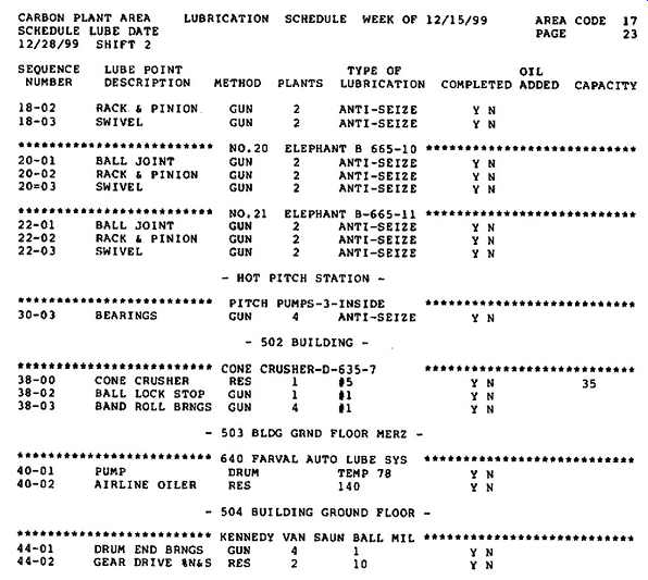
FIG. 2 Typical lubrication schedule.
A major step in developing the lubrication program is to assign specific responsibility and authority for the lubrication program to a competent maintainability or maintenance engineer. The primary functions and steps involved in developing the program are to:
1. Identify every piece of equipment that requires lubrication.
2. Ensure that every piece of major equipment is uniquely identified, prefer ably with a prominently displayed number.
3. Ensure that equipment records are complete for manufacturer and physical location.
4. Determine the locations on each piece of equipment that need to be lubricated.
5. Identify the lubricant to be used.
6. Determine the best method of application.
7. Establish the frequency or interval of lubrication.
8. Determine if the equipment can be safely lubricated while operating or if it must be shut down.
9. Decide who should be responsible for any human involvement.
10. Standardize lubrication methods.
11. Package the previous elements into a lubrication program.
12. Establish storage and handling procedures.
13. Evaluate new lubricants to take advantage of state-of-the-art advances.
14. Analyze any failures involving lubrication and initiate necessary corrective actions.
Lubrication Program Implementation. An individual supervisor in the maintenance department should be assigned the responsibility for implementation and continued operation of the lubrication program. This person's primary functions are to:
• Establish lubrication service actions and schedules.
• Define the lubrication routes by building, area, and organization.
• Assign responsibilities to specific persons.
• Train lubricators.
• Ensure that supplies of proper lubricants are stocked through the storeroom.
• Establish feedback that ensures completion of assigned lubrication and follows up on any discrepancies.
• Develop a manual or computerized lubrication scheduling and control system as part of the larger maintenance management program.
• Motivate lubrication personnel to check equipment for other problems and to create work requests where feasible.
• Ensure continued operation of the lubrication system.
It’s important that a responsible person who recognizes the value of thorough lubrication be placed in charge of this program. As with any activity, interest diminishes over time, equipment is modified without corresponding changes to the lubrication procedures, and state-of-the-art advances in lubricating technology may not be employed. A factory may have thousands of lubricating points that require attention.
Lubrication is no less important to computer systems, even though they are often perceived as electronic. The computer field engineer must provide proper lubrication to printers, tape drives, and disks that spin at 3,600 rotations per minute (rpm). A lot of maintenance time is invested in lubrication. The effect on production uptime can be measured nationally in billions of dollars.
Calibration. Calibration is a special form of preventive maintenance whose objective is to keep measurement and control instruments within specified limits. A standard must be used to calibrate the equipment. Standards are derived from parameters established by the National Bureau of Standards (NBS). Secondary standards that have been manufactured to close tolerances and set against the primary standard are available through many test and calibration laboratories and often in industrial and university tool rooms and research laboratories. Ohmmeters are examples of equipment that should be calibrated at least once a year and before further use if subjected to sudden shock or stress.
Standards. The government sets forth calibration system requirements in MIL-C 45662 and provides a good outline in the military standardization handbook MIL HDBK-52, Evaluation of Contractor's Calibration System. The principles are equally applicable to any industrial or commercial situation. The purpose of a calibration system is to prevent tool inaccuracy through prompt detection of deficiencies and timely application of corrective action. Every organization should prepare a written description of its calibration system. This description should cover measuring test equipment and standards, including:
• Establishing realistic calibration intervals.
• Listing all measurement standards.
• Establishing environmental conditions for calibration.
• Ensuring the use of calibration procedures for all equipment and standards.
• Coordinating the calibration system with all users.
• Ensuring that equipment is frequently checked by periodic system or cross checks in order to detect damage, inoperative instruments, erratic readings, and other performance-degrading factors that cannot be anticipated or provided for by calibration intervals.
• Providing timely and positive correction action.
• Establishing decals, reject tags, and records for calibration labeling.
• Maintaining formal records to ensure proper controls.
Inspection Intervals. The checking interval may be in terms of time (hourly, weekly, monthly), or based on amount of use (every 5,000 parts), or every lot. For electrical test equipment, the power-on time may be a critical factor and can be measured through an electrical elapsed-time indicator.
Adherence to the checking schedule makes or breaks the system. The interval should be based on stability, purpose, and degree of usage. If initial records indicate that the equipment remains within the required accuracy for successive calibrations, then the intervals may be lengthened; however, if equipment requires frequent adjustment or repair, the intervals should be shortened. Any equipment that does not have specific calibration intervals should be (1) examined at least every six months, and (2) calibrated at intervals of no longer than one year.
Adjustments or assignment of calibration intervals should be done so that a minimum of 95 percent of equipment or standards of the same type is within tolerance when submitted for regularly scheduled recalibration. In other words, if more than 5 percent of a particular type of equipment is out of tolerance at the end of its interval, then the interval should be reduced until less than 5 percent is defective when checked.

FIG. 3 A typical calibration label.
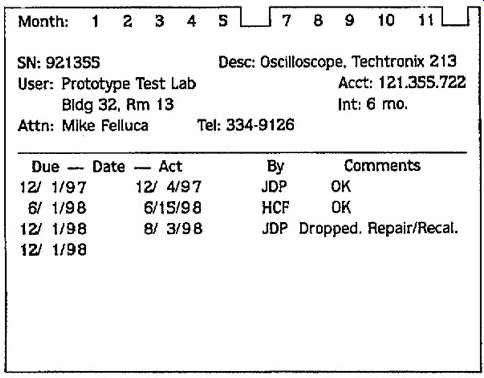
FIG. 4 A typical calibration card.
Control Records. A record system should be kept on every instrument, including:
• History of use
• Accuracy
• Present location
• Calibration interval and when due
• Calibration procedures and necessary controls
• Actual values of latest calibration
• History of maintenance and repairs
Test equipment and measurement standards should be labeled to indicate the date of last calibration, by whom it was calibrated, and when the next calibration is due (see FIG. 3). When the size of the equipment limits the application of labels, an identifying code should be applied to reflect the serviceability and due date for next calibration. This provides a visual indication of the calibration serviceability status. Both the headquarters calibration organization and the instrument user should maintain a two-way check on calibration. A simple means of doing this is to create a small form for each instrument with a calendar of weeks or months (depending on the interval required) across the top, which can be punched and noticed to indicate the calibration due date. An example of this type of form is shown in FIG. 4.
If the forms are sorted every month, the cards for each instrument that should be recalled for check or calibration can easily be pulled out.
Alignment Practices:
Shaft alignment is the proper positioning of the shaft centerlines of the driver and driven components (e.g., pumps, gearboxes) that make up the machine drive train.
Alignment is accomplished either through shimming or moving a machine component. Its objective is to obtain a common axis of rotation at operating equilibrium for two coupled shafts or a train of coupled shafts.
Shafts must be aligned as perfectly as possible to maximize equipment reliability and life, particularly for high-speed equipment. Alignment is important for directly coupled shafts, as well as coupled shafts of machines that are separated by distance- even those using flexible couplings. It’s important because misalignment can intro duce a high level of vibration, cause bearings to run hot, and result in the need for frequent repairs. Proper alignment reduces power consumption and noise level, and helps achieve the design life of bearings, seals, and couplings.
Alignment procedures are based on the assumption that one machine-train component is stationary, level, and properly supported by its baseplate and foundation. Both angular and offset alignment must be performed in the vertical and horizontal planes, which is accomplished by raising or lowering the other machine components and/or moving them horizontally to align with the rotational centerline of the stationary shaft.
The movable components are designated as "machines to be moved" (MTBM) or "machines to be shimmed" (MTBS). MTBM generally refers to corrections in the horizontal plane, whereas MTBS generally refers to corrections in the vertical plane.
Too often, alignment operations are performed randomly and adjustments are made by trial and error, resulting in a time-consuming procedure.
Alignment Fundamentals. This section discusses the fundamentals of machine alignment and presents an alternative to the commonly used trial-and-error method. This section addresses exactly what alignment is and the tools needed to perform it, why it’s needed, how often it should be performed, what is considered to be "good enough," and what steps should be taken before performing the alignment procedure.
It also discusses types of alignment (or misalignment), alignment planes, and why alignment is performed on shafts as opposed to couplings.
Shafts are considered to be in alignment when they are colinear at the coupling point.
The term colinear refers to the condition when the rotational centerlines of two mating shafts are parallel and intersect (i.e., join to form one line). When this is the case, the coupled shafts operate just like a solid shaft. Any deviation from the aligned or co linear condition, however, results in abnormal wear of machine-train components such as bearings and shaft seals.
Variations in machine-component configuration and thermal growth can cause mounting-feet elevations and the horizontal orientations of individual drive-train components to be in different planes. Nevertheless, they are properly aligned as long as their shafts are colinear at the coupling point.
Note that it’s important for final drive-train alignment to compensate for actual operating conditions because machines often move after startup. Such movement is generally the result of wear, thermal growth, dynamic loads, and support or structural shifts.
These factors must be considered and compensated for during the alignment process.
The tools most commonly used for alignment procedures are dial indicators, adjustable parallels, taper gauges, feeler gauges, small-hole gauges, and outside micrometer calipers.
Why Perform Alignment and How Often?
Periodic alignment checks on all coupled machinery are considered one of the best tools in a preventive maintenance program.
Such checks are important because the vibration effects of misalignment can seriously damage a piece of equipment. Misalignment of more than a few thousandths of an inch can cause vibration that significantly reduces equipment life.
Although the machinery may have been properly aligned during installation or during a previous check, misalignment may develop over a very short period. Potential causes include foundation movement or settling, accidentally bumping the machine with another piece of equipment, thermal expansion, distortion caused by connected piping, loosened hold-down nuts, expanded grout, rusting of shims, and others. Indications of misalignment in rotating machinery are shaft wobbling, excessive vibration (in both radial and axial directions), excessive bearing temperature (even if adequate lubrication is present), noise, bearing wear pattern, and coupling wear.
Many alignments are done by the trial-and-error method. Although this method may eventually produce the correct answers, it’s extremely time consuming and, as a result, it’s usually considered "good enough" before it really is. Rather than relying on "feel" as with trial-and-error, some simple trigonometric principles allow alignment to be done properly with the exact amount of correction needed either measured or calculated, taking the guesswork out of the process. Such accurate measurements and calculations make it possible to align a piece of machinery on the first attempt.
What Is Good Enough? This question is difficult to answer because there are vast differences in machinery strength, speed of rotation, type of coupling, and so on. It also is important to understand that flexible couplings don’t cure misalignment problems-a common myth in industry. Although they may somewhat dampen the effects, flexible couplings are not a total solution.
An easy (perhaps too easy) answer to the question of what is good enough is to align all machinery to comply exactly with the manufacturers' specifications; however, the question of which manufacturers' specifications to follow must be answered because few manufacturers build entire assemblies. Therefore, an alignment is not considered good enough until it’s well within all manufacturers' tolerances and a vibration analysis of the machinery in operation shows the vibration effects caused by misalignment to be within the manufacturers' specifications or accepted industry standards. Note that manufacturers' alignment specifications may include intentional misalignment during "cold" alignment to compensate for thermal growth, gear lash, and the like during operation.
Coupling Alignment versus Shaft Alignment. If all couplings were perfectly bored through their exact center and perfectly machined about their rim and face, it might be possible to align a piece of machinery simply by aligning the two coupling halves; however, coupling eccentricity often results in coupling misalignment. This does not mean that dial indicators should not be placed on the coupling halves to obtain alignment measurements. It does mean that the two shafts should be rotated simultaneously when obtaining readings, which makes the couplings an extension of the shaft centerlines, whose irregularities won’t affect the readings.
Although alignment operations are performed on coupling surfaces because they are convenient to use, it’s extremely important that these surfaces and the shaft "run true." If there is any runout (i.e., axial or radial looseness) of the shaft and/or the coupling, a proportionate error in alignment will result. Therefore, before making alignment measurements, the shaft and coupling should be checked and corrected for runout.
Balancing Practices:
Mechanical imbalance is one of the most common causes of machinery vibration and is present to some degree on nearly all machines that have rotating parts or rotors.
Static, or standing, imbalance is the condition when more weight is exerted on one side of a centerline than the other; however, a rotor may be in perfect static balance and not be in a balanced state when rotating at high speed.
If the rotor is a thin disc, careful static balancing may be accurate enough for high speeds. If the rotating part is long in proportion to its diameter, however, and the unbalanced portions are at opposite ends or in different planes, the balancing must counteract the centrifugal force of these heavy parts when they are rotating rapidly.
This section provides information needed to understand and solve most balancing problems using a vibration/balance analyzer, a portable device that detects the level of imbalance, misalignment, and so on in a rotating part based on the measurement of vibration signals.
Sources of Vibration:
Caused by Mechanical Imbalance. Two major sources of vibration caused by mechanical imbalance in equipment with rotating parts or rotors are assembly errors and incorrect key length guesses during balancing.
Assembly errors. Even when parts are precision balanced to extremely close tolerances, vibration caused by mechanical imbalance can be much greater than necessary because of assembly errors. Potential errors include relative placement of each part's center of rotation, location of the shaft relative to the bore, and cocked rotors.
Center of rotation. Assembly errors are not simply the additive effects of tolerances, but also include the relative placement of each part's center of rotation. For example, a "perfectly" balanced blower rotor can be assembled to a "perfectly" balanced shaft and yet the resultant imbalance can be high. This can happen if the rotor is balanced on a balancing shaft that fits the rotor bore within 0.5mil (0.5 thousandths of an inch) and then is mounted on a standard cold-rolled steel shaft allowing a clearance of more than 2mils.
Shifting any rotor from the rotational center on which it was balanced to the piece of machinery on which it’s intended to operate can cause an assembly imbalance four to five times greater than that resulting simply from tolerances. Therefore, all rotors should be balanced on a shaft with a diameter as nearly the same as the shaft on which it will be assembled.
For best results, balance the rotor on its own shaft rather than on a balancing shaft.
This may require some rotors to be balanced in an overhung position, a procedure the balancing shop often wishes to avoid; however, it’s better to use this technique rather than being forced to make too many balancing shafts. The extra precision balance attained by using this procedure is well worth the effort.
Method of locating position of shaft relative to bore. Imbalance often results with rotors that don’t incorporate setscrews to locate the shaft relative to the bore (e.g., rotors that are end-clamped). In this case, the balancing shaft is usually horizontal.
When the operator slides the rotor on the shaft, gravity causes the rotor's bore to make contact at the 12 o'clock position on the top surface of the shaft. In this position, the rotor is end-clamped in place and then balanced.
If the operator removes the rotor from the balancing shaft without marking the point of bore and shaft contact, it may not be in the same position when reassembled. This often shifts the rotor by several mils as compared to the axis on which it was balanced, thus introducing an imbalance. The vibrations that result are usually enough to spoil what should have been a precision balance and produce a barely acceptable vibration level. In addition, if the resultant vibration is resonant with some part of the machine or structure, a more serious vibration could result.
To prevent this type of error, the balancer operators and those who do final assembly should follow the following procedure: (1) The balancer operator should permanently mark the location of the contact point between the bore and the shaft during balancing. (2) When the equipment is reassembled in the plant or the shop, the assembler should also use this mark. (3) For end-clamped rotors, the assembler should slide the bore on the horizontal shaft, rotating both until the mark is at the 12 o'clock position and then clamp it in place.
Cocked rotor. If a rotor is cocked on a shaft in a position different from the one in which it was originally balanced, an imbalanced assembly will result. If , for example, a pulley has a wide face that requires more than one setscrew, it could be mounted on-center but be cocked in a different position than during balancing. This can happen by reversing the order in which the setscrews are tightened against a straight key during final mounting as compared to the order in which the setscrews were tightened on the balancing arbor. This can introduce a pure couple imbalance, which adds to the small couple imbalance already existing in the rotor and causes unnecessary vibration.
For very narrow rotors (e.g., disc-shaped pump impellers or pulleys), the distance between the centrifugal forces of each half may be very small. Nevertheless, a very high centrifugal force, which is mostly counterbalanced statically (discussed in Section 16.2.1) by its counterpart in the other half of the rotor, can result. If the rotor is slightly cocked, the small axial distance between the two very large centrifugal forces causes an appreciable couple imbalance, which is often several times the allow able tolerance because the centrifugal force is proportional to half the rotor weight (at any one time, half of the rotor is pulling against the other half) times the radial distance from the axis of rotation to the center of gravity of that half.
To prevent this, the assembler should tighten each setscrew gradually-first one, then the other, and back again-so that the rotor is aligned evenly. On flange-mounted rotors such as flywheels, it’s important to clean the mating surfaces and the bolt holes.
Clean bolt holes are important because high couple imbalance can result from the assembly bolt pushing a small amount of dirt between the surfaces, cocking the rotor.
Burrs on bolt holes can also produce the same problem.
Other. Other assembly errors can cause vibration. Variances in bolt weights when one bolt is replaced by one of a different length or material can cause vibration. For setscrews that are 90 degrees apart, the tightening sequence may not be the same at final assembly as during balancing. To prevent this, the balancer operator should mark which setscrew was tightened first.
Key length. With a keyed-shaft rotor, the balancing process can introduce machine vibration if the assumed key length is different from the length of the one used during operation. Such an imbalance usually results in a mediocre or "good" running machine as opposed to a very smooth running machine.
For example, a "good" vibration level that can be obtained without following the precautions described in this section is amplitude of 0.12 in./sec. (3.0mm/sec.). By following the precautions, the orbit can be reduced to about 0.04 in./sec. (1mm/sec.).
This smaller orbit results in longer bearing or seal life, which is worth the effort to ensure that the proper key length is used.
When balancing a keyed-shaft rotor, one half of the key's weight is assumed to be part of the shaft's male portion. The other half is considered part of the female portion that is coupled to it. When the two rotor parts are sent to a balancing shop for rebalancing, however, the actual key is rarely included. As a result, the balance operator usually guesses at the key's length, makes up a half key, and then balances the part.
(Note: A "half key" is of full-key length but only half-key depth.) In order to prevent an imbalance from occurring, don’t allow the balance operator to guess the key length. It’s strongly suggested that the actual key length be recorded on a tag that is attached to the rotor to be balanced. The tag should be attached so that another device (such as a coupling half, pulley, fan, etc.) cannot be attached until the balance operator removes the tag.
Theory of Imbalance. Imbalance is the condition when more weight is exerted on one side of a centerline than the other. This condition results in unnecessary vibration, which generally can be corrected by adding counterweights. There are four types of imbalance: (1) static, (2) dynamic, (3) couple, and (4) dynamic imbalance combinations of static and couple.
Static. Static imbalance is single-plane imbalance acting through the center of gravity of the rotor, perpendicular to the shaft axis. This imbalance can also be separated into two separate single-plane imbalances, each acting in-phase or at the same angular relationship to each other (i.e., 0 degrees apart); however, the net effect is as if one force is acting through the center of gravity. For a uniform straight cylinder, such as a simple paper machine roll or a multigrooved sheave, the forces of static imbalance measured at each end of the rotor are equal in magnitude (i.e., the ounce inches or gram-centimeters in one plane are equal to the ounce-inches or gram centimeters in the other).
In static imbalance, the only force involved is weight. For example, assume that a rotor is perfectly balanced and, therefore, won’t vibrate regardless of the speed of rotation. Also, assume that this rotor is placed on frictionless rollers or "knife edges." If a weight is applied on the rim at the center of gravity line between two ends, the weighted portion immediately rolls to the 6 o'clock position because of the gravitational force.
When rotation occurs, static imbalance translates into a centrifugal force. As a result, this type of imbalance is sometimes referred to as force imbalance, and some balancing machine manufacturers use the word force instead of static on their machines; however, when the term force imbalance was just starting to be accepted as the proper term, an American standardization committee on balancing terminology standardized the term static instead of force. The rationale was that the role of the standardization committee was not to determine and/or correct right or wrong practices, but simply to standardize those currently in use by industry. As a result, the term static imbalance is now widely accepted as the international standard and, therefore, is the term used in this document.
Dynamic. Dynamic imbalance is any imbalance resolved to at least two correction planes (i.e., planes in which a balancing correction is made by adding or removing weight). The imbalance in each of these two planes may be the result of many imbalances in many planes, but the final effects can be characterized to only two planes in almost all situations.
An example of a case where more than two planes are required is flexible rotors (i.e., long rotors running at high speeds). High speeds are considered to be revolutions per minute (rpm) higher than about 80 percent of the rotor's first critical speed; however, in more than 95 percent of all common rotors (e.g., pump impellers, armatures, generators, fans, couplings, pulleys), two-plane dynamic balance is sufficient. Therefore, flexible rotors are not covered in this guide because of the low number in operation and the fact that balancing operations are almost always performed by specially trained people at the manufacturer's plant.
In dynamic imbalance, the two imbalances don’t have to be equal in magnitude to each other, nor do they have to have any particular angular reference to each other. For example, they could be 0 (in-phase), 10, 80, or 180 degrees from each other.
Although the definition of dynamic imbalance covers all two-plane situations, an understanding of the components of dynamic imbalance is needed so that its causes can be understood. An understanding of the components also makes it easier to under stand why certain types of balancing don’t always work with many older balancing machines for overhung rotors and very narrow rotors. The primary components of dynamic imbalance include number of points of imbalance, amount of imbalance, phase relationships, and rotor speed.
Points of Imbalance. The first consideration of dynamic balancing is the number of imbalance points on the rotor because there can be more than one point of imbalance within a rotor assembly. This is especially true in rotor assemblies with more than one rotating element, such as a three-rotor fan or multistage pump.
Amount of imbalance. The amplitude of each point of imbalance must be known to resolve dynamic balance problems. Most dynamic balancing machines or in situ balancing instruments are able to isolate and define the specific amount of imbalance at each point on the rotor.
Phase relationship. The phase relationship of each point of imbalance is the third factor that must be known. Balancing instruments isolate each point of imbalance and determine their phase relationship. Plotting each point of imbalance on a polar plot does this. In simple terms, a polar plot is a circular display of the shaft end. Each point of imbalance is located on the polar plot as a specific radial, ranging from 0 to 360 degrees.
Rotor speed. Rotor speed is the final factor that must be considered. Most rotating elements are balanced at their normal running speed or over their normal speed range.
As a result, they may be out of balance at some speeds that are not included in the balancing solution. For example, the wheels and tires on your car are dynamically balanced for speeds ranging from 0 to the maximum expected speed (i.e., 80 miles per hour). At speeds above 80 miles per hour, they may be out of balance.
Coupled Imbalance. Couple imbalance is caused by two equal non-colinear imbalance forces that oppose each other angularly (i.e., 180 degrees apart). Assume that a rotor with pure couple imbalance is placed on frictionless rollers. Because the imbalance weights or forces are 180 degrees apart and equal, the rotor is statically balanced; however, a pure couple imbalance occurs if this same rotor is revolved at an appreciable speed.
Each weight causes a centrifugal force, which results in a rocking motion or rotor wobble. This condition can be simulated by placing a pencil on a table, then at one end pushing the side of the pencil with one finger. At the same time, push in the opposite direction at the other end. The pencil will tend to rotate end-over-end. This end-over-end action causes two imbalance "orbits," both 180 degrees out-of-phase, resulting in a "wobble" motion.
Balancing Standards. The International Standards Organization (ISO) has published standards for acceptable limits for residual imbalance in various classifications of rotor assemblies. Balancing standards are given in ounce-inches or pound-inches per pound of rotor weight or the equivalent in metric units (g-mm/kg). The ounce-inches are for each correction plane for which the imbalance is measured and corrected.
Caution must be exercised when using balancing standards. The recommended levels are for residual imbalance, which is defined as imbalance of any kind that remains after balancing. TBL. 2 is the norm established for most rotating equipment. Additional information can be obtained from ISO 5406 and 5343. Similar standards are available from the American National Standards Institute (ANSI) in their publication ANSI S2.43-1984.
So far, there has been no consideration of the angular positions of the usual two points of imbalance relative to each other or the distance between the two correction planes.
For example, if the residual imbalances in each of the two planes were in-phase, they would add to each other to create more static imbalance.
Most balancing standards are based on a residual imbalance and don’t include multiplane imbalance. If they are approximately 180 degrees to each other, they form a couple. If the distance between the planes is small, the resulting couple is small; if the distance is large, the couple is large. A couple creates considerably more vibration than when the two residual imbalances are in-phase. Unfortunately, nothing in the balancing standards considers this point.
Another problem could also result in excessive imbalance-related vibration even though the ISO standards were met. The ISO standards call for a balancing grade of G6.3 for components such as pump impellers, normal electric armatures, and parts of process plant machines. This results in an operating speed vibration velocity of 6.3 mm/sec. (0.25 in./sec.) vibration a velocity; however, practice has shown that an acceptable vibration velocity is 0.1 in./sec. and the ISO standard of G2.5 is required.
Because of these discrepancies, changes in the recommended balancing grade are expected in the future.
===
TBL. 2 Balance Quality Grades for Various Groups of Rigid Rotors
Balance Quality Grade ---- Type of Rotor
G4,000 Crankshaft drives of rigidly mounted slow marine diesel engines with uneven number of cylinders.
G1,600 Crankshaft drives of rigidly mounted large two-cycle engines.
G630 Crankshaft drives of rigidly mounted large four-cycle engines; crankshaft drives of elastically mounted marine diesel engines.
G250 Crankshaft drives of rigidly mounted fast four-cylinder diesel engines.
G100 Crankshaft drives of fast diesel engines with six or more cylinders; complete engines (gasoline or diesel) for cars and trucks.
G40 Car wheels, wheel rims, wheel sets, drive shafts; crankshaft drives of elastically mounted fast four-cycle engines (gasoline and diesel) with six or more cylinders; crankshaft drives for engines of cars and trucks.
G16 Parts of agricultural machinery; individual components of engines (gasoline or diesel) for cars and trucks.
G6.3 Parts or process plant machines; marine main-turbine gears; centrifuge drums; fans; assembled aircraft gas-turbine rotors; flywheels; pump impellers; machine-tool and general machinery parts; electrical armatures.
G2.5 Gas and steam turbines; rigid turbo-generator rotors; rotors; turbo compressors; machine-tool drives; small electrical armatures; turbine driven pumps.
G1 Tape recorder and phonograph drives; grinding-machine drives.
G0.4 Spindles, disks, and armatures of precision grinders; gyroscopes.
===
Motivation
Staff motivation to perform preventive maintenance properly is a critical issue. A little extra effort in the beginning to establish an effective preventive maintenance program will pay large dividends, but finding those additional resources when so many "fires" need to be put out is a challenge. Like with most things we do, if we want to do it, we can. Herzberg's two levels of motivation, as outlined in FIG. 5, help us under stand the factors that cause people to want to do some things and not be so strongly stimulated to do others. Paying extra money , for example, is not nearly as motivating as are demonstrated results that show equipment running better because of the preventive maintenance and a good "pat on the back" from management for a job well done.
A results orientation is helpful because, as shown in FIG. 6, an unfilled need is the best motivator. That need, in reference to effective maintenance management, is equipment availability and reliability, desire to avoid breakdowns, and opportunity to achieve improvement. The converse is failures and downtime, with resulting low production and angry customer users.
Next>>