AMAZON multi-meters discounts AMAZON oscilloscope discounts
(<< cont. from part 1)
Pressure-Injection Regrouting
Pressure-grouting is a repair process whereby equipment can be reaffixed on the foundation without lifting the equipment, without completely chipping away the old grout, and without repositioning and complete regrouting. Pressure grouting should not, however, be considered a panacea. Nevertheless, when properly used it can be a valuable tool.
Shoulder Removal Method
Pressure-injection regrouting techniques offer equipment operators important advantages of reduced downtime, lower labor costs, and less revenue lost from idle equipment. These techniques make possible satisfactory and long life re-grouts with machine downtime at a minimum.
FIG. 18 shows typical damage before making repairs. Figure 19 is the first step in conducting repairs where the old grout is chipped away along with any damaged or oil soaked concrete. It is desirable to remove enough old grout from beneath the machine so that a load bearing area equivalent to a rail or sole plate mounting can be provided by the epoxy grout once it has been poured. If the foundation itself is cracked, it should be repaired before proceeding further. Otherwise, the effectiveness of the regrout will not be maintained over a long period of time.
After the old grout has been chipped away, holes are drilled into the remaining grout for the installation of injection tubes, and are usually spaced 18 in., or approximately 45 cm, apart (see FIG. 20). The copper tubing installed in these holes should be sealed with epoxy putty or electrician's putty as illustrated in FIG. 21.
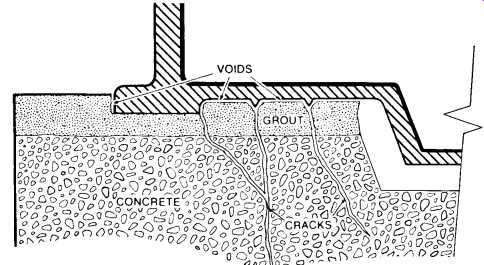
FIG. 18. Illustrating the damage done to a compressor foundation before
making repairs by pressure-injection regrouting, shoulder removal method
().
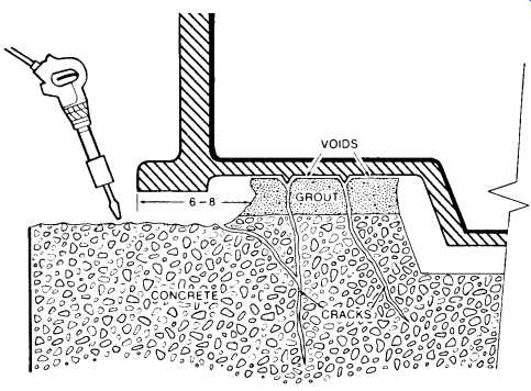
FIG. 19. The first step of repair is to remove the shoulder and about
1/2 of the load-bearing area using a pneumatic jumbo rivet buster.
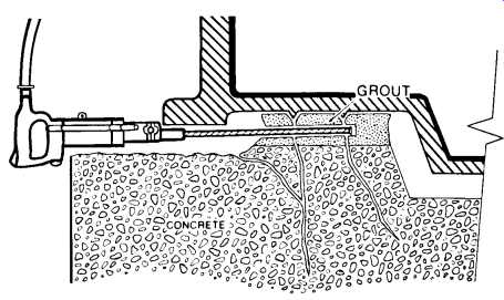
FIG. 20. Drilling of injection holes into the old grout using a pneumatic
drill.
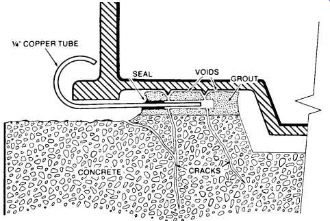
FIG. 21. Installing copper tubes for pressure-injection.
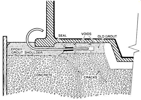
FIG. 22. Installing forms and repouring the shoulder with an epoxy grout.
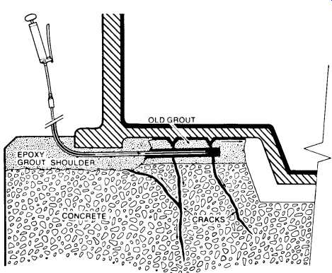
FIG. 23. Removing forms and pressure-injecting an epoxy adhesive into
the cracks and voids under the machine base. Excess epoxy is drained
into the trough under the oil pan ().
Before installing forms, all anchor bolts should be isolated to provide at least a 1/4 in. barrier. This minimizes the possibility of later stress cracking of the grout shoulder and also allows stretching of the anchor bolt from the bottom of the nut to the bottom of the anchor bolt sleeve when torquing the anchor bolts. Forms should be designed to provide a grout level of at least one in. above the machine base (see FIG. 22). This raised shoulder acts as an effective horizontal restraint for the machine and thereby reduces lateral movement. Forms should be near liquid tight to contain the epoxy grout mortar. Any holes in the forms can be plugged with electrician's putty before pouring the mortar. Forms should be waxed with a quality paste wax before installation in order to facilitate easy removal.
Once the forms have been poured and the grout cured for approximately 24 hours, pressure-injection regrouting is carried out to provide a liquid shim of epoxy between the remaining old grout and the equipment base as illustrated in FIG. 23. Once this shim of grout has cured, the forms are removed and the foundation dressed and painted according to FIG. 24.
FIG. 24. The foundation is dressed and painted, thereby completing the repairs.
FIG. 25. Method of rectifying grout installation where surface foam was present.
Through-the-Case Method
Occasionally, in spite of the best intentions, proper techniques are not used and grout failure results. The cause might be air trapped under the equipment when grouting, or foam under the equipment because of improper grout preparation, or loss of adhesion caused by improper surface preparation. Whatever the cause, there is movement that must be stopped. If the grout and foundation are in good structural condition, pressure-grouting through the case may be a practical solution to the problem. Refer to FIG. 25 for a good illustration of this grouting method.
With this procedure, the equipment is shut down and the oil removed and cleaned from the crankcase. Holes are drilled through the case and tapped to accommodate grease fittings. Usually, holes are drilled on about two-ft centers. Alignment is then checked and corrected as necessary. A grease fitting is installed in one of the holes near the center and pressure grouting is begun. Dial indicator gauges should be used to confirm that pressure grouting is being accomplished without lifting the equipment.
Pressure grouting should proceed in both directions from the center. As soon as clear epoxy escapes from the adjacent hole, a grease fitting is installed and injection is begun at the next location. This step-wise procedure is continued until clear epoxy is forced from all sides of the equipment. After curing, alignment is rechecked and the equipment returned to service.
FIG. 26. Pressure grouting of sole plates
Pressure Grouting Sole Plates
Occasionally when installing sole plates, a contractor will fail to clean them properly before grouting. Later this will cause loss of adhesion and result in excessive movement. Pressure grouting of sole plates can be accomplished with a relatively high degree of success if proper techniques are used. Refer to FIG. 26 for an illustration of this procedure.
A small pilot hole is drilled through the sole plate at a 45° angle beginning about one-third of the distance from the end of the sole plate. The hole is then counterbored. The pilot hole is reamed out and tapped to accommodate 1/8 in. pipe. Fittings are installed and epoxy can be injected while the equipment is running until the epoxy begins to escape around the outer periphery of the sole plate as illustrated. Usually, oil is flushed out from beneath the sole plate along with the epoxy. Flushing should be continued until clear epoxy appears. It is not uncommon that flow will channel to the extent that epoxy will escape from only 30 to 40 percent of the sole plate circumference during the first injection. The epoxy will begin to gel in about 15 minutes at the operating temperature of 160° to 180°F. A second injection is carried out after sufficient gelling has been accomplished to restrict flow to ungrouted areas. Two or three injections at about 15-minute intervals are usually required to effect 100 percent coverage under the sole plate. Epoxy will bond through a thin lubricating oil film at about 150 to 200 psi.
One person should be assigned for every two to three sole plates that are loose. To the extent possible, pressure grouting of all sole plates should proceed at the same time. Once the grouting is complete, the equipment should be shut down for at least 6 hours to allow the epoxy to cure. Alignment should be checked and chocks machined or shimmed, if necessary, before the equipment is returned to service.
This technique has also been used without shutting the equipment down. However, it is somewhat less reliable under these circumstances.
Nevertheless, if for some unknown reason a sole plate comes loose after it has been grouted, the process can be repeated. It is a simple matter to remove the fittings, rebore and retap the hole, and thereby use the same injection site.
Pressure grouting sole plates seldom changes alignment. We attribute this to the fact that excess epoxy is squeezed from beneath the sole plate by the weight of the equipment. For purposes of illustration, assume the equipment is being aligned with the aid of jack screws having hexagonal heads and ten threads per in. One revolution of the screw would raise or lower the equipment 100/1000; moving the screw one face would create a change of 1/6 this amount or 16/1000. However, one face change on a jack screw is scarcely detectable when measuring web deflections. Nevertheless, the film thickness of epoxy under the sole plate should be far less than 16/1000. Thus, alignment should not be changed when equipment is pressure-grouted.
Pre-filled Equipment Base-plates: How to Get a Superior Equipment Installation for Less Money
Why Be Concerned
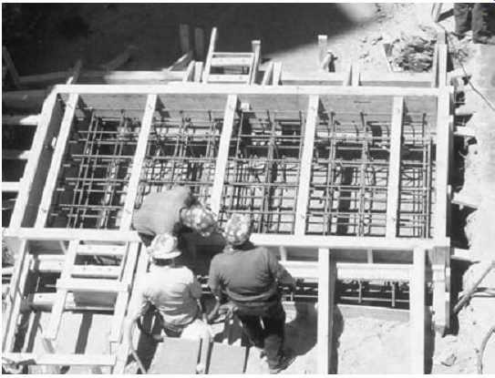
FIG. 27. Construction of machinery foundation.
Proper field installation of rotating equipment has a tremendous impact on the life-cycle cost of machinery. According to statistical reliability analysis, as much as 65 percent of the life-cycle costs are determined during the design, procurement, and installation phases of new machinery applications. While design and procurement are important aspects for any application, the installation of the equipment plays a very significant role. A superb design, poorly installed, gives poor results. A moderate design, properly installed, gives good results.
A proper installation involves many facets, such as good foundation design, no pipe strain, and proper alignment, just to name a few. All of these issues revolve around the idea of reducing dynamic vibration in the machinery system. Great design effort and cost are expended in the construction of a machinery foundation, as can be seen in FIG. 27. The machinery foundation, and the relationship of F = ma, is extremely important to the reliability of rotating equipment. Forces and mass have a direct correlation on the magnitude of vibration in rotating equipment systems.
The forces acting on the system, such as off-design operating conditions, unbalance, misalignment, and looseness, can be transient and hard to quantify. An easier and more conservative way to minimize motion in the system is to utilize a large foundational mass. Through years of empirical evidence, the rule of thumb has been developed that the foundation mass should be three to five times the mass of the centrifugal equipment system.
How well the machinery system is joined to the foundation system is the key link to a proper installation and to reduced vibration. The base plate, or skid, of the machinery system must become a monolithic member of the foundation system. Machinery vibration should ideally be transmitted through the baseplate to the foundation and down through the subsoil. "Mother earth" can provide very effective damping, i.e., modification of vibration frequency and attenuation of its amplitude. Failure to do so results in the machinery resonating on the baseplate, as shown in FIG. 28. Proper machinery installation results in significant increase in mean time between failures (MTBF), longer life for mechanical seal and bearings, and a reduction in life-cycle cost.
The issue is to determine the most cost-effective method for joining the equipment baseplate to the foundation. Various grouting materials and methods have been developed over the years, but the quest always boils down to cost: life-cycle costs versus first cost. It's the classic conflict between the opposing goals of reliability professionals and project personnel. Machinery engineers want to use an expensive baseplate design with epoxy grout; project engineers want to use a less expensive baseplate design with cementitious grout.
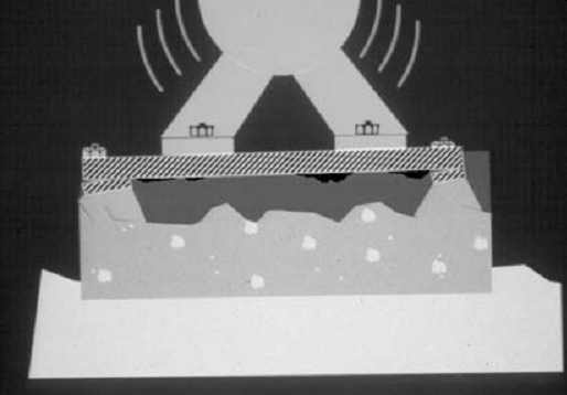
FIG. 28. Machinery vibration.
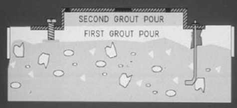
FIG. 29. Two-pour grout method.
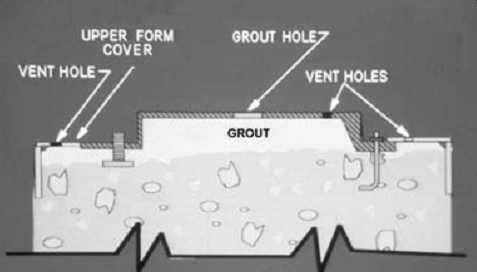
FIG. 30. One-pour grout method.
A new grouting method, the Stay-Tru Pregrouted Baseplate System, and a new installation technique, the Stay-Tru Field Installation System, bridge the gap, and utilizing these two systems satisfies the requirements of both job functions.
Conventional Grouting Methods
The traditional approach to joining the baseplate to the foundation has been to build a liquid-tight wooden form around the perimeter of the foundation, and fill the void between the baseplate and the foundation with either a cementitious or epoxy grout. There are two methods used with this approach, the two-pour method, shown in FIG. 29, and the one pour method, shown in FIG. 30.
The two-pour method is the most widely used, and can utilize either cementitious or epoxy grout. The wooden grout forms for the two-pour method are easier to build because of the open top. The void between the foundation and the bottom flange of the baseplate is filled with grout on the first pour, and allowed to set. A second grout pour is performed to fill the cavity of the baseplate, by using grout holes and vent holes provided in the top of the baseplate.
The one-pour grouting method reduces labor cost, but requires a more elaborate form-building technique. The wooden grout form now requires a top plate that forms a liquid-tight seal against the bottom flange of the baseplate. The form must be vented along the top seal plate, and be sturdy enough to withstand the hydraulic head produced by the grout. All of the grout material is poured through the grout holes in the top of the base plate. This pour technique requires good flow characteristics from the grout material, and is typically used for epoxy grout applications only.
Field Installation Problems Explained
Grouting a baseplate or skid to a foundation requires careful attention to many details. A successful grout job provides a mounting surface for the equipment that is flat, level, very rigid, and completely bonded to the foundation system. Many times these attributes are not obtained during the first attempt at grouting, and expensive field-correction techniques have to be employed. The most prominent installation problems involve voids and distortion of the mounting surfaces.
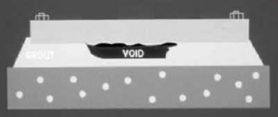
FIG. 31. Grout void under baseplate.
Voids and Bonding Issues
As shown in FIG. 31, the presence of voids at the interface between the grout material and the bottom of the baseplate negates the very purpose of grouting. Whether the void is one inch deep, or one-thousandth of an inch deep, the desired monolithic support system has not been achieved. Voids prevent resonance of the foundation system and preclude the dampening of resonance and shaft-generated vibration.
The creation of voids can be attributed to a number of possible causes:
• Insufficient vent holes in baseplate
• Insufficient static head during grout pour
• Non-optimum grout material properties
• Improper surface preparation of baseplate underside
• Improper surface primer
Insufficient vent holes or static head are execution issues that can be addressed through proper installation techniques. Insufficient attention usually leaves large voids. The most overlooked causes of voids are related to bonding issues. These types of voids are difficult to repair because of the small crevices to be filled.
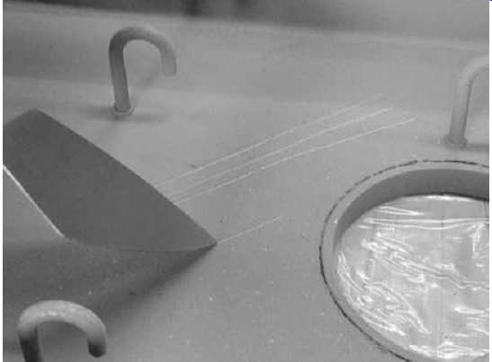
FIG. 32. Soft inorganic zinc primer.
The first issue of bonding has to do with the material properties of the grout. Cementitious grout systems have little or no bonding capabilities.
Epoxy grout systems have very good bonding properties, typically an average of 2,000 psi tensile adherence to steel, but surface preparation and primer selection greatly affect the bond strength. The underside of the baseplate must be cleaned, and the surface must be free of oil, grease, moisture, and other contaminants. All of these contaminants greatly reduce the tensile bond strength of the epoxy grout system.
The type of primer used on the underside of the baseplate also affects the bond between the epoxy grout and the baseplate. Ideally, the best bonding surface would be a sandblasted surface with no primer. Since this is not feasible for conventional grouting methods, a primer must be used, and the selection of the primer must be based on its tensile bond strength to steel. The epoxy grout system bonds to the primer, but the primer must bond to the steel baseplate to eliminate the formation of voids. The best primers are epoxy based, and have minimum tensile bond strength of 1,000 psi. Other types of primers, such as inorganic zinc, have been used, but the results vary greatly with how well the inorganic zinc has been applied.
FIG. 32 shows the underside of a baseplate sprayed with inorganic zinc primer. The primer has little or no strength, and can be easily removed with the tip of a trowel. The inorganic zinc was applied too thickly, and the top layer of the primer is little more than a powdery matrix. The ideal dry film thickness for inorganic zinc is three mils, and is very hard to achieve in practice. The dry film thickness for this example is 9 to 13 mils, as shown in FIG. 33.
The consequences of applying epoxy grout to such a primer are shown in FIG. 34, a core sample taken from a baseplate that was free of voids for the first few days. As time progressed, a void appeared, and over the course of a week the epoxy grout became completely "dis-bonded" from the baseplate. The core sample shows that the inorganic zinc primer bonded to the steel baseplate, and the epoxy grout bonded to the inorganic zinc primer, but the primer delaminated. It sheared apart because it was applied too thickly and created a void across the entire top of the baseplate.
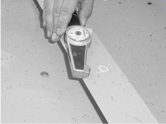
FIG. 33. Dry film thickness indicator.
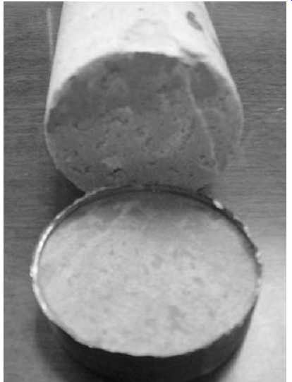
FIG. 34. Baseplate core sample with zinc primer.
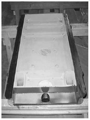
FIG. 35. Underside of American Petroleum Institute (API) baseplate.
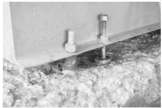
FIG. 36. Anchor bolt and jack bolt system.
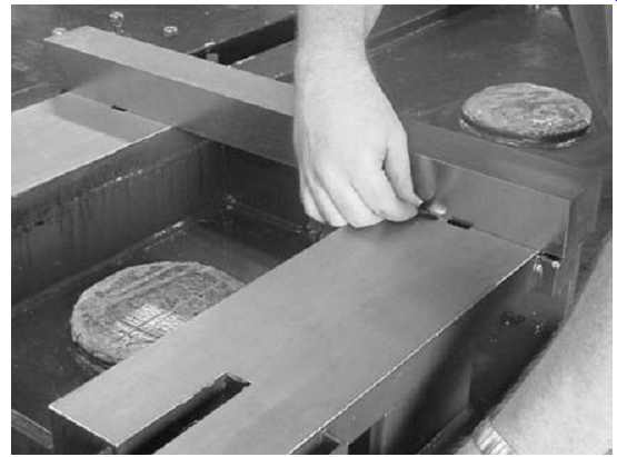
FIG. 37. Flatness and coplanar check.
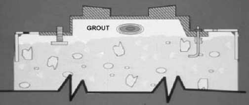
FIG. 38. Grout cure and mounting surface distortion.
Distortion of Mounting Surfaces
Another field installation problem with costly implications is distortion of the baseplate's machined surfaces. This distortion can be either induced prior to grouting due to poor field leveling techniques, or generated by the grout itself.
Baseplate designs have become less rigid over time. Attention has been focused on the pump end of the baseplate to provide enough structural support to contend with nozzle load requirements. The motor end of the baseplate is generally not as rigid, as shown in FIG. 35. The process of shipping, lifting, storing, and setting the baseplate can have a negative impact on the motor mounting surfaces. Although these surfaces may have initially been flat, there often is work to be done when the baseplate reaches the field.
Using the system of jack bolts and anchor bolts of FIG. 36, the mounting surfaces can be reshaped during the leveling process, but the concepts of flatness and level have become confused. Flatness cannot be measured with a precision level, and unfortunately this has become the practice of the day. A precision level measures slope in inches per foot, and flatness is not a slope, it is a displacement. In the field, flatness should be measured with either a ground straightedge or bar and a feeler gauge, as shown in FIG. 37, not with a level. Once the mounting surfaces are determined to be flat, then the baseplate can be properly leveled. This con fusion has caused many baseplates to be installed with the mounting surfaces out of tolerances for both flatness and level.
The other issue of mounting surface distortion comes from the grout itself. All epoxy grout systems have a slight shrinkage factor. While this shrinkage is very small, typically 0.0002=/in, the tolerances for flatness and level of the mounting surfaces are also very small. The chemical reaction that occurs when an epoxy grout resin and hardener are mixed together results in a volume change that is referred to as shrinkage.
Chemical cross-linking and volume change occur as the material cools after the exothermic reaction. Epoxy grout systems cure from the inside out, as shown in FIG. 38. The areas closest to the baseplate vs. grout interface experience the highest volume change.
Baseplates with sturdy cross-braces are not affected by the slight volume change of the grout. For less rigid designs, the bond strength of the epoxy grout can be stronger than the baseplate itself. Referring back to FIG. 38, after the grout has cured the motor mounting surfaces become distorted and are no longer coplanar. Tolerances for alignment and motor soft foot become very difficult to achieve in this scenario. This "pull-down" phenomenon has been proven by finite element analysis (FEA) modeling and empirical lab tests jointly performed by a major grout manufacturer and an industrial grout user.
Hidden Budget Busters
Correcting the problems of voids and mounting surface distortion in the field is a very costly venture. Repairing voids takes a lot of time, patience, and skill to avoid further damage to the baseplate system. Field machining the mounting surfaces of a baseplate also involves commodities that are in short supply: time and money.
The real problem with correcting baseplate field installation problems is that the issues of "repair" are not accounted for in the construction budget. Every field correction is a step backward in both time and money. For a fixed-cost project, the contractor must absorb the cost. In a cost-plus project, the client is faced with the cost. Either way, the parties will have a meeting, which is just another drain on available time and money.
Pregrouted Baseplates
The best way to solve a problem is to concentrate on the cause, rather than developing solutions addressing the effects. The answer for resolving field installation problems is not to develop better void repair procedures or field machining techniques, it is to eliminate the causes of voids and mounting surface distortion.
A new baseplate grouting system has been developed to address the causes of field installation problems. The term pre-grouted baseplate sounds simple enough, but addressing the causes of installation problems involves far more than slipping a baseplate over and filling it up with grout.
In that scenario, the issues of surface preparation, bonding, and mounting surface distortion still have not been addressed. A proper pre-grouted base plate provides complete bonding to the baseplate underside, contains zero voids, and provides mounting surfaces that are flat, coplanar, and colinear within the required tolerances. To assure that these requirements are met, a good pre-grout system will include the following.
Proper Surface Preparation
Baseplates that have been specified with an epoxy primer on the under side should be solvent washed, lightly sanded to remove the grossly finish, and solvent washed again. For inorganic zinc and other primer systems, the bond strength to the metal should be determined. There are several methods for determining this, but as a rule of thumb, if the primer can be removed with a putty knife, the primer should be removed. Sandblasting to an SP-6 finish is the preferred method for primer removal. After sand blasting, the surface should be solvent washed, and grouted within 8 hours.
Void-free Grout Installation
By its very nature, pregrouting a baseplate greatly reduces the problems of entrained air creating voids. However, because grout materials are highly viscous, proper placement of the grout is still important to prevent developing air pockets. The baseplate must also be well supported to prevent severe distortion of the mounting surfaces due to the weight of the grout.
A side benefit to using a pregrouted baseplate system is the ability to successfully use cementitious grouts as the fill material. With conventional installation methods, cementitious grout is very difficult to place and has no bond strength to the metal baseplate. With the pregrout system, an epoxy-based concrete adhesive can be applied to the metal prior to the placement of the grout, as shown in FIG. 39. This technique provides bond strength equal to the tensile strength of the cementitious grout, which is around 700 psi.
For epoxy grout systems, flow ability is no longer an issue, and highly loaded systems can now be employed. Adding pea gravel to the epoxy grout system increases the yield, increases the strength, and reduces the shrinkage factor. FIG. 40 shows an application using a high-fill epoxy grout system.
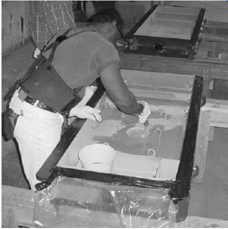
FIG. 39. Epoxy bond adhesive for cementitious grout.
Postcuring of the Grout
As mentioned earlier, epoxy grout systems undergo a slight volume change during the curing process. For conventional installation methods, this physical property creates distortion. While the effects are greatly reduced with the pregrouted system, it is still necessary to allow the epoxy grout to fully cure before any inspection or correction to the mounting surfaces is performed. FIG. 41 shows a time vs. cure chart that can be used for epoxy grout systems.
For cementitious grout systems, the material should be kept wet and covered for at least 3 days to help facilitate the curing process. While cementitious grout systems are nonshrink and don't induce distortion to the mounting surfaces, the postcuring process helps to achieve full compressive strength. To further enhance the curing process, after 24 hours the grout surface can be sealed with an epoxy resin to prevent contamination and water evaporation (FIG. 42).
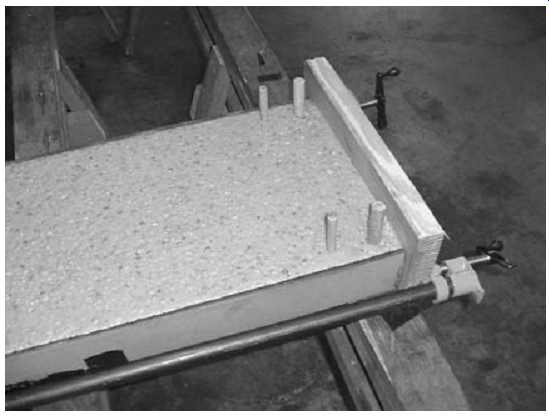
FIG. 40. High-fill epoxy grout system.
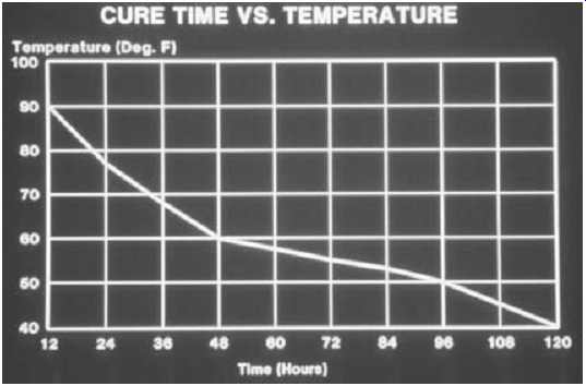
FIG. 41. Epoxy grout cure time vs. temperature.
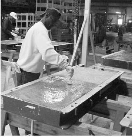
FIG. 42. Epoxy sealer for cementitious grout.
Mounting Surfaces
Once the pre-grout baseplate has been fully cured, a complete inspection of the mounting surfaces should be performed. If surface grinding of the mounting surfaces is necessary, then a postmachining inspection must also be performed. Careful inspection for flatness, coplanar, and relative level (colinear) surfaces should be well documented for the construction or equipment files. The methods and tolerances for inspection should conform to the following:
Flatness. A precision ground parallel bar is placed on each mounting surface. The gap between the precision ground bar and the mounting surface is measured with a feeler gauge. The critical areas for flatness are within a 2= to 3= radius of the equipment hold down bolts. Inside of this area, the measured gap must be less than 0.001=. Outside the critical area, the measured gap must be less than 0.002=. If the baseplate flatness falls outside of these tolerances, the baseplate needs to be surface ground.
Coplanar. A precision ground parallel bar is used to span across the pump and motor mounting pads in five different positions, three lateral and two diagonal. At each location, the gap between the precision ground bar and the mounting surfaces is measured with a feeler gage. If the gap at any location along the ground bar is found to be more than 0.002=, the mounting pads are deemed non-coplanar, and the baseplate will need to be surface ground.
Relative Level (Colinear). It is important to understand the difference between relative level and absolute level. Absolute level is the relation ship of the machined surfaces to the earth. The procedure for absolute level is done in the field, and is not a part of this inspection. Relative level is an evaluation of the ability to achieve absolute level before the base plate gets to the field.
The procedure for this evaluation is based on a rough level condition.
A Starrett 98 or similar precision level is placed on each machine surface and the rough level measurement, and direction recorded for each machine surface. The rough level measurements of each surface are then compared to each other to determine the relative level. The difference between the rough level measurements is the relative level. The tolerance for relative level is 0.010=/ft.
Field Installation Methods for Pregrouted Baseplates
The use of a proper pregrouted baseplate system eliminates the problem areas associated with field installations. The baseplate has been filled with grout that has properly bonded and is void free. All the mounting surfaces have been inspected, corrected, and documented to provide flat, coplanar, and colinear surfaces. The next step is to join the prefilled baseplate to the foundation system. This can be done using either conventional grouting methods or a new grouting method that is discussed later.
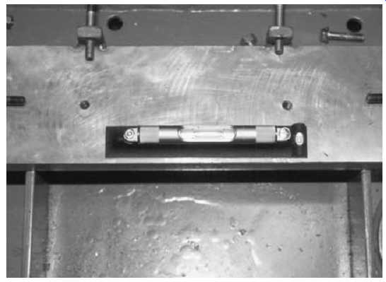
FIG. 43. Field leveling in axial direction.
Field Leveling
Knowing that the mounting surfaces already meet flatness and coplanar tolerances makes field leveling of the baseplate very easy. Because the prefilled baseplate is very rigid, it moves as a system during the leveling process. The best method is to use a precision level for each mounting surface. This gives you a clear picture of the position of the baseplate to absolute level. The level must also fit completely inside the footprint of the mounting surface to read properly. If the level is larger than the mounting surface, use a smaller level or a ground parallel bar to ensure that the ends of the level are in contact with the surface.
With the levels in position, adjust the jack bolt and anchor bolt system to the desired height for the final grout pour, typically 1 1/2 to 2 inches for conventional grout. With the grout height established, the final adjustments for level can be made. The baseplate should be leveled in the longitudinal or axial direction first, as shown in FIG. 43, and then in the transverse direction, as shown in FIG. 44.
Conventional Grouting Method
Using the conventional method for installing a pregrouted baseplate is no different from the first pour of a two-pour grout procedure. After the concrete foundation has been chipped and cleaned, and the baseplate has been leveled, grout forms must be constructed to hold the grout (FIG. 45). To prevent trapping air under the prefilled baseplate, all the grout material must be poured from one side. As the grout moves under the base plate, it pushes the air out. Because of this, the grout material must have good flow characteristics. To assist the flow, a head box should be constructed and kept full during the grouting process.
FIG. 44. Field leveling in transverse direction.
Hydraulic Lift of a Pregrouted Baseplate
It is important when using a head box that the pregrouted baseplate is well secured in place. The jack bolt and anchor bolt system must be tight, and the anchor bolt nut should be locked down to the equivalent of 30 to 45 ft-lbs.
The bottom of a pregrouted baseplate provides lots of flat surface area.
The specific gravity of most epoxy grout systems is in the range of 1.9 to 2.1. Large surface areas and very dense fluids create an ideal environment for buoyancy. TBL. 1 shows the inches of grout head necessary to begin lifting a pregrouted American National Standards Institute (ANSI) base plate. During the course of a conventional grouting procedure, it is very common to exceed the inches of head necessary to lift a pre-filled base plate. For this reason, it is very important to assure that the baseplate in locked down. As a point of interest, the whole range of American Petroleum Institute (API) baseplates listed in Appendix M of API 610 can be lifted with 9 inches of grout head.
Baseplate Stress Versus Anchor Bolt Torque
With the necessity of using the jack bolt and anchor bolt system to lock the pregrouted baseplate in position, it is important to determine if this practice introduces stresses to the baseplate. It is also important to remember that any induced stresses are not permanent stresses, provided they remain below the yield strength of the baseplate. The anchor bolts will be loosened, and the jack bolts removed, after the grout has cured.
An FEA analysis was performed on a pregrouted ANSI baseplate and a pregrouted API baseplate. The baseplates that were analyzed had six anchor bolt and jack bolt locations, used 3/4= bolts, and was based on 45 ft-lbs and 100 ft-lbs of torque to the anchor bolts. The 100 ft-lbs of torque was considered to be extremely excessive for leveling and locking down a baseplate, but was analyzed as a worst-case scenario.
The peak local stress loads for 45 ft-lbs was 14,000 psi, and 28,000 psi for 100 ft-lbs. Most baseplates are fabricated from ASTM A36 steel, which has a yield stress of 36,000 psi. As FIG. 46 shows, the stresses are very localized and decay very rapidly. The result of the FEA analysis shows that the effect of locking down the pregrouted baseplate does not induce any detrimental stresses.
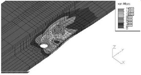
FIG. 46. Stresses due to 45 ft-lbs anchor bolt preload.
New Field Grouting Method for Pre-grouted Baseplates
Conventional grouting methods for nonfilled baseplates, by their very nature, are labor and time intensive. Utilizing a pregrouted baseplate with conventional grouting methods helps to minimize some of the cost, but the last pour still requires a full grout crew, skilled carpentry work, and good logistics. To further minimize the costs associated with baseplate installations, a new field grouting method has been developed for pregrouted baseplates. This new method utilizes a low-viscosity, high strength epoxy grout system that greatly reduces foundation preparation, grout form construction, crew size, and the amount of epoxy grout used for the final pour.
While there may be other low-viscosity, high-strength epoxy grout systems available on the market, the discussion and techniques that follow are based on the flow and pour characteristics of Escoweld 7560. This type of low viscosity grout system can be poured from 1/2= to 2= depths, has the viscosity of thin pancake batter, and is packaged and mixed in a liquid container. As shown in FIG. 47, this material can be mixed and poured with a two-man crew.
Concrete Foundation Preparation
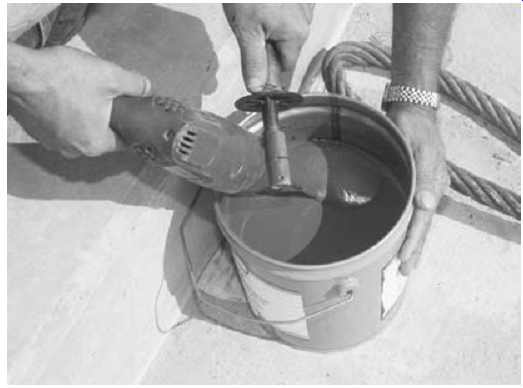
FIG. 47. Mixing of low viscosity epoxy grout.
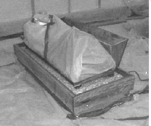
FIG. 45. Pregrout installation using conventional method.
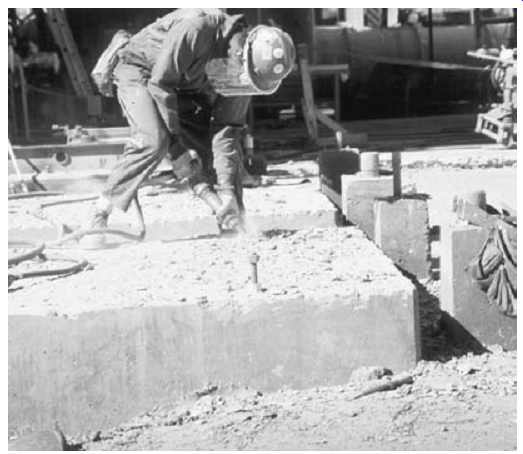
FIG. 48. Chipping of concrete foundation.
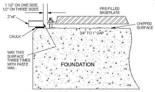
FIG. 49. New grout installation technique.
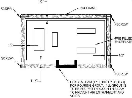
FIG. 50. New grout-forming technique.
One of the leading conflicts on epoxy grout installations is the issue of surface preparation of the concrete foundation. Removing the cement lattice on the surface of the concrete is very important for proper bonding, but this issue can be carried to far (FIG. 48). Traditional grouting methods require plenty of room to properly place the grout, and this requires chipping all the way to the shoulder of the foundation. Utilizing a low-viscosity epoxy grout system greatly reduces the amount of concrete chipping required to achieve a proper installation.
The new installation method allows for the chipped area to be limited to the footprint of the baseplate (FIG. 49). A bushing hammer can be used to remove the concrete lattice, and the required depth of the final grout pour is reduced to 3/4= to 1=.
New Grout-forming Technique
With the smooth concrete shoulder of the foundation still intact, a very simple "2 ¥ 4" grout form can be used (FIG. 50). One side of the simple grout form is waxed, and the entire grout form is sealed and held in place with caulk (refer back to FIG. 49). While the caulk is setting up, a simple head box can be constructed out of dux seal. Due to the flow characteristics of the low-viscosity epoxy grout, this head box does not need to be very large or very tall.
The low viscosity epoxy grout is mixed with a hand drill, and all the grout is poured through the head box to prevent trapping an air pocket under the baseplate.
This new installation method has been used for both ANSI- and API style baseplates with great success. With this technique, field experience has shown that a pregrouted baseplate can be routinely leveled, formed, and poured with a two-man crew in 3 to 4 hours.
===
TBL. 4 Lifting Forces for ANSI Baseplates Grout Head Pressure Required to Lift a Pregrouted Baseplate ANSI Type Baseplates
===
Field Installation Cost Comparison
The benefits of using a pregrouted baseplate with the new installation method can be clearly seen when field installation costs are compared.
This comparison looks at realistic labor costs, and does not take any credit for the elimination of repair costs associated with field installation problems, such as void repair and field machining.
Years of experience with grouting procedures and related systems point to an average-size grout crew for conventional installations as eight men.
As of 2004, an actual man-hour labor cost of $45/hr can be easily defended when benefits and overhead are included.
A cost comparison can be developed, based on the installation of a typical API baseplate using epoxy grout, for the conventional two-pour procedure and a pregrouted baseplate using the new installation method.
The following conditions apply:
Baseplate dimensions: 72=¥ 36=¥ 6=
Foundation dimensions: 76=¥ 40=¥ 2= (grout depth)
Labor cost: $45/hr
Epoxy grout cost: $111/cubic ft
A baseplate with the listed dimensions can be pre-grouted for $2,969.
This cost would include surface preparation, epoxy grout, surface grinding, and a guaranteed inspection.
TBL. 2 shows a realistic accounting of time and labor for the installation of a typical API baseplate. The total installed cost for a conventional two-pour installation is $6,259. The total installed cost for a pregrouted baseplate, installed with the new installation method, is $4,194. That's a cost savings of almost 50 percent. More importantly, the installation is void-free and the mounting surfaces are in tolerance.
TBL. 5 Cost Comparison for Two-Pour vs. New Method: Installation Labor Cost for Two-Pour Procedure; Installation Labor Cost for Stay-Tru System
Consider Prefilled Baseplates
It is possible to satisfy the concerns of both the project engineer and the machinery engineer regarding rotating equipment installation. The issues of first costs versus life-cycle costs can be reconciled with this new approach to machinery field installations. As an added bonus, the term repair can be eliminated from the grouting experience.
SECTION-A
Detailed Checklist for Rotating Equipment: Horizontal Pump Baseplate Checklist
SECTION-B
Specification for Portland Cement Grouting of Rotating Equipment
SECTION-C
Detailed Checklist for Rotating Equipment: Baseplate Grouting
SECTION-D
Specifications for Epoxy Grouting of Rotating Equipment
SECTION-E
Specification and Installation of Pregrouted Pump Baseplates
This appendix, or standard procedure, outlines the requirements for specifying and installing pregrouted machinery baseplates. How ever, this standard does not cover the installation requirements for machinery mounted on sole plates. A typical application for this standard procedure would be the installation or retrofit of an ANSI or API pump.
I. Purpose
The purpose of the standard procedure is to provide specific requirements for pre-filling any machinery baseplate, or, in particular, a pump baseplate, with epoxy grout, and machining the mounting surfaces of the baseplate after the grout has cured. Additionally, the standard procedure outlines the requirements for installing the pregrout baseplate in the field, utilizing a special grouting technique for the final grout pour. This special technique makes use of a low-viscosity epoxy grout for the final pour. The technique greatly reduces the field costs associated with traditional installation methods.
By utilizing this standard procedure, baseplate-mounted machinery can be installed with zero voids, eliminating the possibility of expensive field machining, and reducing field installation costs by 40 to 50 percent.
II. Specification of Pre-grouted Baseplates
1. The underside of the baseplate to be pregrouted must be sand blasted to white metal to remove all existing paint, primer, or scale.
2. Any tapped bolt holes that penetrate through the top of the baseplate, such as the coupling guard holding down bolts, must be filled with the appropriate-sized bolts and coated with never seize to create the necessary space for bolt installation after grouting of the baseplate.
3. Anchor bolt or jack bolt holes, located inside the grouted space of the baseplate, must have provisions for bolt penetration through the baseplate after grouting.
4. If the baseplate has grout holes and/or vent holes, these holes must be completely sealed prior to grouting.
5. All pregrouted baseplates will be filled with catalyzed epoxy grout or a premium nonshrink cement grout.
6. Once the baseplate has been filled with epoxy grout, the grout must be completely cured before any machining is performed.
7. The machining of the baseplate must be set up to assure that the baseplate is under no stress or deformation.
8. Prior to machining, the baseplate must be adjusted and leveled to assure that no more than 0.020= of metal is removed at the lowest point.
9. The baseplate will have two (2) mounting surfaces for the driver, and two (2) to four (4) mounting surfaces for the driven equipment. The flatness tolerance for all these mounting surfaces will be 0.001= per ft. The finished surface roughness must be no more than an 85P profiled surface.
10. The two (2) mounting surfaces for the driver must be coplanar within 0.002=. The two (2) to four (4) mounting surfaces for the driven equipment must also be coplanar within 0.002=. The original dimensional relationship (elevation) between the driver mounting surfaces and the driven mounting surfaces must be maintained to within 0.020=.
11. Once the machining process has been completed, an "as machined" tolerance record must be taken, and provided with the pregrouted baseplate.
III. General Field Grouting Requirements
1. The epoxy grout utilized for the final field grout pour is a low viscosity epoxy grout. This grout has a special aggregate and has the consistency of thin pancake batter. This allows for a very thin final grout pour, with the optimum vertical thickness being 3/4=.
2. All grout material components must be stored in a dry and weatherproof area in original unopened containers. Under no circumstances should grouting components be stored outside subject to rain or under a tarpaulin with no air circulation.
3. For optimum handling characteristics, precondition the resin and hardener to a temperature between 64° and 90°F.
4. The work area, including foundation and machinery, must be protected from direct sunlight and rain. This covering (shading) should be erected 48 hours prior to alignment and grouting, and shall remain until 24 hours after placement of the grout, by which time the grout will have cured and returned to ambient temperature. The shading is also to prevent the foundation from becoming wet. It is important that the concrete remain dry prior to grouting.
5. Grouting shall be scheduled to take place during early morning or afternoon hours depending on the surface temperatures.
6. Just before starting the grouting operation, the temperature of the concrete foundation and machinery shall be taken using a surface thermometer. Ideal surface temperatures shall be between 70° and 90°F.
IV. Foundation Preparation
1. The concrete must be chipped to expose a minimum of 50 percent aggregate so as to remove all laitance and provide a rough surface for bonding. Hand-chipping guns only will be used. No jackhammers will be permitted. If oil or grease are present, affected areas will be chipped out until free of oil or grease.
2. The concrete to be chipped should not extend more than 2= outside the "footprint" of the pregrouted baseplate. Low viscosity epoxy grout can be poured only up to a 2= depth, and should not extend more than 2= from the edge of the baseplate.
By limiting the chipped area of the concrete to just outside the foot print of the baseplate, simple forming techniques can be utilized.
3. After chipping, the exposed surface must be blown free of dust and concrete chips using oil- and water-free compressed air from an approved source. Concrete surface can also be vacuumed.
4. After the foundation has been chipped and cleaned, adequate precautions must be taken to ensure that there is no contamination of the concrete surfaces. To prevent debris, loose materials, or parts from falling on the top of the concrete, properly cover the workspace with polyethylene sheet.
5. The foundation bolt threads must be protected during the grouting operations.
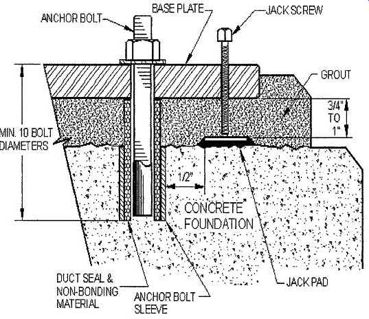
6. As regards the bolts (FIG. E-l), which will be tensioned after grouting, care must be taken to prevent the bolt surfaces from coming in contact with the epoxy grout. All anchor bolts should have grout sleeves, which must be filled with a nonbonding material to prevent the epoxy grout from filling the grout sleeve.
This can be accomplished by protecting the anchor bolt before hand between the top of the grout sleeve and the underside of the baseplate by wrapping the bolt with foam insulation, Dux Seal, or other non-bonding material.
V. Pregrouted Baseplate Preparation
1. Prior to positioning the baseplate over the foundation, the bottom side of the prefilled baseplate must be solvent washed to remove any oil or other contaminants from the surface. After the surface has been cleaned, sand the surface to break the glaze of the epoxy grout.
2. Vertical edges of the baseplate that come in contact with the epoxy grout must be radiused/chamfered to reduced stress concentration in the grout.
3. Vertical jackscrews should be provided at each anchor bolt. The jackscrews will be used to level the pregrouted baseplate. These jackscrews will be removed after the low-viscosity epoxy cures, generally 24 hours after placement at 78°F.
4. Leveling pads should be used under each jackscrew to prevent the baseplate from "walking" while leveling the baseplate. The pads will remain in the grout, and must be made from stainless steel. The pads must have radius edges and rounded corners to reduce stress concentrations in the grout.
5. With the jackscrews and leveling pads in place, level the pre grouted baseplate to 0.002=/foot for API applications and 0.005=/ foot for ANSI applications.
6. After the baseplate has been leveled, the jackscrews must be greased or wrapped with Dux-Seal to facilitate their removal once the grout has cured. Wax is not a suitable releasing agent.
VI. Forming
1. Low-viscosity epoxy grout should only be poured up to a 2=depth, and should not extend more than 2= from the edge of the baseplate. The optimum pour depth is 3/4= to 1=. The best wood-forming material for this product is a "2 by 4".
2. Any wood surface coming in contact with epoxy grout shall be coated three times with paste floor wax. (Liquid wax or oil is not acceptable as an alternative.) All forms must be waxed three times before the forms are placed on the foundation. Do not wax the wood surface that comes in contact with the foundation.
This may prevent the silicone sealant from sticking to the form board, and forming a proper seal. Care should be taken to prevent any wax from falling on the concrete foundation or the baseplate.
3. In most cases, there is very little room between the side of the baseplate and the edge of the foundation. To help position the form boards, it is best to fasten the boards together with wood screws or nails. One side of the form should leave an opening between the board and the baseplate that measures 1= to 2=. The other three sides should have a separation of 1/2= to 3/4=.
The larger side will be used to pour the low-viscosity epoxy grout.
4. Forms shall be made liquid tight. Silicone sealant that does not cure to a hard consistency is best suited for this application. A sealant that remains pliable will facilitate easy removal. The best approach is to apply the sealant directly on the foundation, where the front edge of the form will fall, and then press the form down to create the seal. Check for cracks and openings between the form and the foundation, and apply additional sealant where needed. Allow at least an hour for the sealant to cure before pouring the grout.
5. Because of the small depth of the epoxy grout pour, it will be very difficult to use a chamfer stripe to create a bevel around the outside of the form. The best approach is to use a grinder after the grout has cure to create a bevel.
6. Once the forms boards are in place, a small "head box" can be made using blocks of duct seal. To help create a slight head for the grout, build a duct seal dam on the side of the baseplate with the larger opening. The dam should be about 3= tall, 12= long, and form a rectangle by connecting the two short sides direct to the baseplate. The end result will be a 3= head box that will be used to pour and place all the epoxy grout. The best location for the head box is the midpoint of the baseplate.
VII. Grouting Procedure for Low-Viscosity Epoxy Grout
1. The required number of units of epoxy grout, including calculated surplus, should be laid out close to the grouting location.
The 1/2= drill and mixer blade should be prepared for the grouting operation.
2. Low-viscosity epoxy grout is a three-component, high-strength, 100 percent solids epoxy grouting compound. The resin, hardener, and aggregate are supplied in a 6-gallon mixing container.
One unit produces 0.34 cubic feet of grout.
Inspection of Work Site
Check for:
• Proper shading
• Preparation of concrete, baseplate, jackscrews, leveling pads
• Wood forms properly waxed and sealed
• Foundation bolts wrapped and sealed
Before Mixing
Check for:
• Mixing equipment clean
• Surface temperature of epoxy grout components (<90°F)
• Ambient temperature (<95°F)
While Mixing
Check for:
• Slow drill motor rpm's to avoid entrapping air
• Resin and hardener mixed 3 minutes (use the timer)
Before Pouring
Check for:
• Temperature of concrete foundation (<95°F)
• Temperature of the machinery baseplate (<95°F)
While Pouring
Check for:
• Continuous operation
• Adequate head to fill corners in baseplate
After Pouring
Check for:
• Ambient temperature for the record
• Maintaining head until the grout starts to set
Curing
Check for:
• Work site kept shaded for 24 hours to avoid sharp temperature increase
• Formwork left in place until grout is no longer tacky to the touch