AMAZON multi-meters discounts AMAZON oscilloscope discounts
What's an Epoxy?
According to the Handbook of Epoxy Resins, the term epoxy refers to a chemical group consisting of an oxygen atom bonded with two carbon atoms already united in some other way. The simplest epoxy is a three membered ring. There is no universal agreement on the nomenclature of the three-membered ring. There is division even on the term epoxy itself- the Europeans generally prefer the term epoxide, which is doubtless more correct than the American epoxy.
In addition to providing a history of the development of epoxy resins, the handbook states that the resins are prepared commercially thus:
1. By dehydrohalogenation of the chlorohydrin prepared by the reaction of epichlorohydrin with a suitable di- or polyhydroxyl material or other active-hydrogen-containing molecule.
2. By the reaction of olefins with oxygen-containing compounds such as peroxides or peracids.
3. By the dehydrohalogenation of chlorohydrins prepared by routes other than by route .
Dozens of distinct types of resins are commercially available, and the term epoxy resin is generic. It now applies to a wide family of materials.
Both solid and liquid resins are available.
There are other liquid resins such as phenolics, polyesters, acrylics, etc., which cure in similar fashion, but the epoxy resins possess a rather unique combination of properties. The liquid resins and their curing agents form low-viscosity, easy-to-modify systems. They can cure at room temperatures, without the addition of external heat and they cure without releasing by-products. They have low shrinkage compared to other systems.
They have unusually high bond strengths, excellent chemical resistance, high abrasion resistance, and good electrical insulation properties.
The basic properties can be modified by blending resin types, by selection of curing agents (hardeners), the addition of modifiers, and by adding fillers.
Perhaps the most valuable single property of the epoxy resins is their ability to cure, thus converting from liquids to tough, hard solids. This is accomplished by the addition of a curing agent. Some agents promote curing by catalytic action, while others participate directly in the reaction and become part of the resin chain. Depending upon the particular agent, curing may be accomplished at room temperature with heat produced by exothermic reaction, or may require application of external heat. The epoxies will react with over 50 different chemical groupings, but the basic curing agents employed in the epoxy resin technology are Lewis bases, inorganic bases, primary and secondary amines, and amides.
An entire spectrum of properties can be obtained in a cured epoxy resin system by careful selection of resins, careful selection of curing agents, varying the ratio of resin to curing agent and by including additives or fillers. The resins and curing agents, themselves, may even be blends. As an illustration of the spectrum of obtainable properties, a cured epoxy system may be as soft as a rubber ball or so hard that it will shatter when dropped. Epoxies can be formulated to be either sticky or tack free. They can be formulated to either melt or char when heated; to release tremendous amounts of heat when curing or they may require heat for curing; to bond tenaciously to sandblasted steel, even under cryogenic conditions, or have relatively little bond; or to be either tough or friable.
Epoxy Grouts
Grout is a broad term covering all of those materials used in a wide variety of applications which include clinking for cracks, fissures, or cavities; a mortar for tile and other masonry; a support for column footings; a sealant for built-in vessels; or a mortar for setting heavy machinery. This text, however, is concerned with those epoxy-based materials used in setting heavy machinery and in repairing concrete foundations. Specifications for Portland cement grouting and epoxy grouting of rotating equipment, as well as a checklist for baseplate grouting, can be found in at the end of this section.
The need for a machinery grout is created by a combination of circumstances occurring in the construction of foundations. Many of these circumstances are unfavorable to concrete, thereby complicating its use.
This condition is brought about primarily because it is impossible to pour a concrete foundation to within the tolerances usually required for precision leveling and alignment of dynamic equipment. Even if such exact placement were possible it would be further complicated by the fact that concrete shrinks while curing.
Furthermore, the laitance or weak surface created when simple concrete is cast or troweled would not provide sound support for machinery requiring precision alignment. It has therefore become a standard practice in construction of foundations to pour the concrete to a level slightly above the desired grade, and after curing, chip away the surface to remove the laitance. The machinery is then positioned on the foundation, leveled and aligned to within proper tolerances with the aid of jack screws, wedges, shims, etc., and the gap grouted in solidly to establish integrity between the machine base and the concrete foundation below.
When improperly installed machinery breaks loose, the static forces to which the foundation is subjected do not act alone. Vibratory forces of high magnitude will also exist. Given enough time, this will usually cause cracks in the foundation that allow lubricating oil to penetrate deep into the foundation and proceed to degrade the concrete. It therefore becomes necessary to repair the cracked foundation, remove or repair oil-soaked concrete and regrout in order to re-establish the integrity of the system.
Epoxy grouting materials have long been used for these repairs.
The specific use for which grout is intended should be taken into consideration when evaluating the properties of a prospective grout. It is equally important to ascertain the conditions under which a manufacturer obtained his test data.
Some properties contribute to the long service life or performance of a grout while others facilitate the ease of installation or grout placement. In evaluating a prospective grout, performance characteristics should take preference over ease of placement characteristics. These properties are of key importance:
• Nonfoaming---Without a doubt, the single most important characteristic of a grout from a performance standpoint is its ability to stabilize and disperse any air introduced with the aggregate or entrained during normal, nonviolent mixing. Otherwise, a weak, foamy surface would develop soon after pouring, and be unable to maintain alignment. Surface foam can always be eliminated by selecting the proper aggregate and maintaining viscosity of the mixed grout with proper aggregate ratio. This ratio cannot be fixed for all temperature conditions because the viscosities of the liquid ingredients change with temperature as do other hydrocarbons. The aggregate ratio will increase as the temperature of the ingredients becomes higher. Incorporating air release agents and surface defoamers in the grout formulations does improve the appearance of the exposed foundation shoulders, but does not prevent entrapment of air bubbles under the equipment base. Even with a time lapse between grout mixing and grout placement, air cannot be properly released because of the difference in rise rates of various size air bubbles, particularly in "soupy" mixes.
• Dimensional Stability---Three causes of dimensional change in grouts are shrinkage while curing, thermal expansion or contraction from temperature changes, and stress deformation or creep. Shrink age in epoxy grout systems can occur if the formulation contains non reactive volatile solvents that can, with time, gradually evaporate from the grout. This material loss usually results in shrinkage or cracking. Shrinkage is also theoretically possible in cases where improper ratio of resin to curing agent exists as a result of dispensing error or as a result of poor or incomplete mixing. Shrinkage is virtually nonexistent in properly formulated and properly mixed epoxy grout.
• Grout Expansion---Thermal expansion coefficients of grouts should be compared with the rate of thermal expansion of concrete and steel since it will be sandwiched between the two materials. Concrete and steel have about the same linear coefficient of thermal expansion.
Unfilled epoxy resin systems expand or contract at about ten times the rate of concrete and steel. The high rate of expansion of unfilled epoxy does not cause problems when the epoxy is of a nonbrittle formulation and is present only in thin films, as in pressure grouting.
When aggregate is added to the liquid epoxy/curing agent mixture to form a mortar, the linear coefficient of thermal expansion can be reduced to the range of 1.2-1.4 x 10⁻⁵ in./in. °F, or about twice the rate for concrete or steel. When reviewing properties of a grout, compressive strengths should be considered along with the modulus of elasticity (the slope of the stress-strain curve). Generally, the more rigid the material, the steeper the slope and the higher the modulus of elasticity. Rubber, for example, is elastic according to the lay definition, but relatively nonelastic according to the technical definition.
• Strength---There are several methods of measuring strength of a grout. It can be measured under compression, tension, impact, and under flexure. Bond strength, shear strength and cleavage are measurements of adhesion rather than strength. Usually when strength of a grout is mentioned, it is the ultimate compressive strength that is implied. The term yield strength should be reserved for tensile tests of metals which work-harden before reaching the ultimate strength.
Grouting materials do not work-harden, and there is but one peak in the stress-strain curve. More important than the ultimate strength, however, is the proportional limit, because beyond that level of stress, the material is permanently distorted and will not return to its original dimension after the load is removed. Data from compression tests can be used for design calculations because static loads are usually known and dynamic loads can be reasonably estimated. Grout is seldom placed under tension, except at rail ends, etc., during start up. The tensile strength of the grout is important, because if it is known at the operating temperature, the maximum distance between expansion joints can be calculated. In addition to the tensile strength, tensile modulus of elasticity, operating temperature range, and linear coefficient of thermal expansion must be known.
This should illustrate that epoxy grouts are sophisticated products.
There are literally thousands of possible resin/curing agent combinations.
Developing, manufacturing, and marketing of epoxy grouts is not the business for small time formulators with bath tub and boat paddle type equipment. Prospective epoxy grout suppliers should be screened on the basis of their technology and capabilities. If the reader retains nothing more than this one fact, he will have learned within a short period what others have learned through great anguish over a long period and at considerable expense.
Proper Grout Mixing Is Important
Epoxy grouts must be properly mixed if adequate strength is to be maintained at operating temperatures. The strength of epoxy grouts is the result of dense cross-linkage between resin and hardener molecules. Dense cross-linkage cannot occur in either resin-rich or resin-poor areas. Poorly mixed grout, which may appear to be strong at room temperature, can soften and creep under load at temperatures in the operating range.
Epoxy grouts are three-component products. They have an epoxy resin, a hardener, and a graded aggregate. The resin and hardener serve as an adhesive in the mortar while the aggregate serves as a filler to reduce costs.
The addition of an aggregate will lower the coefficient of thermal expansion of the mortar to more closely approach that of concrete and steel.
Aggregates also serve as heat sinks to absorb the heat released by curing, and thereby, allow thicker pours.
Both resin and hardener molecules are surface-active, which means that either is capable of clinging to a surface. That is why it is so critical that the resin and hardener be premixed for a minimum of three minutes before adding aggregate. Use of a paint mixer for premixing these adhesive components is preferred over the stick-and-bucket method because it provides more thorough mixing and will not usually whip air into the mix.
The aggregate used in preparing an epoxy grout mortar is a key factor in minimizing the loss of load bearing area caused by the rising of entrapped air after grout placement. Aggregate quality is also a key in minimizing the potential for run-away curing, edge lifting of the grout on foundation corners, loss of bond to the machinery base and stress cracking of the grout.
Most aggregates have about 25-30 percent voids regardless of particle sizes or gradation. The liquid components of an epoxy grout have a density of about 9 lbs per gallon while the aggregate exhibits a bulk density of about 14-16 lbs per gallon. The particle density is much higher. Because of this difference in densities, the aggregate falls to the bottom of the mix and is not immediately wetted. When the liquid and aggregate are blended together, air that was present in the aggregate as well as air introduced into the mortar during mixing has a tendency to rise. The rate at which air bubbles rise is governed by both the size of the bubble as well as the viscosity of the mortar. At any given viscosity, the rise rate increases as the size of the bubble increases; therefore, it is important to keep the size of the bubbles as small as possible. The size of the bubbles is determined by the space between aggregate particles.
The linear coefficient of thermal expansion of unfilled epoxy grout is about ten times greater than that of concrete or steel or 6-8 x 10⁻⁵ in./in. °F. When aggregate is added to form a mortar, the linear coefficient of thermal expansion is reduced, and the more aggregate added, the closer it approaches the coefficient of concrete and steel. It is important that the thermal expansion coefficient of epoxy mortar approach that of concrete and steel in order to minimize edge lifting on foundation corners and to minimize stress cracking of the grout when temperatures fall below the curing temperature. The ratio of aggregate to epoxy adhesive in the mortar should be as high as possible without exceeding the point at which the mortar becomes permeable. As stated earlier, most commercial epoxy grout mortars have a thermal expansion coefficient of about 1.2-1.4 x 10⁻⁵ in./in. °F.
Most epoxy adhesives cure by exothermic reaction, i.e., they release heat on curing. If an epoxy grout cures too fast, high curing temperatures are reached and locked-in stresses may be created after heat dissipation.
Aggregate serves as a heat sink. Consequently, it is usually desirable to have as high an aggregate loading as possible. Because the hydroxide ion accelerates the curing of epoxy resins and because water contains hydroxide ions, it is important that the aggregates used in preparing the mortar be kiln dried. As little as one ounce of water per cubic foot of mortar will dramatically increase curing rates. This small amount of moisture is not detectable by sight or touch. Kiln drying is a common practice with bagged aggregates. Even low cost blasting sands are kiln dried.
The viscosity of the mortar is determined by the viscosity of the liquid (which is determined by temperature), the shape and the amount of aggregate as well as the amount of surface area present in the aggregate. The greater the surface area the greater the viscosity of the mortar. While high viscosity in an epoxy mortar is helpful in reducing the rise rate of air bubbles it also reduces the fluidity of the mortar. A powder aggregate would certainly eliminate air rising problems, but unfortunately, a paste consistency would be reached long before an adequate quantity of aggregate is added to significantly reduce the linear coefficient of the mortar expansion.
A high aggregate loading can be accomplished in mortar without eliminating its fluidity and without creating a permeable mortar by careful grading of near-spherical aggregates. Theoretically, the selection of each particle size should be the largest that will fit in the space between particles of the next larger size. The amount of each grade present should be that which fills these spaces without significantly increasing total volume of the aggregate. The variation in particle size should not be so great as to cause classification of the aggregate in the mortar before curing; otherwise, a gradient in coefficients of thermal expansion may be created between the top and bottom of the grout. The diameter of the largest particles should be no more than 1/10 to 1/15 the thickness of the grout under the load bearing surface of the machinery. The largest particle size in most commercial epoxy grouts is about 1/8 in. Epoxy grout manufacturers usually recommend a minimum grout thickness of 1 1/2 in. Because the adhesive components are organic materials, the viscosities change with temperature. More aggregate is sometimes required when preparing mortar in hot climates than is required when mixing at conventional room temperatures. The proper consistency or viscosity of the mortar is observed when the divot falls free and does not cling to a clean mortar hoe when a gentle chop is made in the mix.
When utilizing a concrete mixer or a mortar mixer for preparing the grout, it is important that mixing after aggregate addition be carried out only long enough to coat all aggregate particles uniformly. Otherwise, a froth may be generated from air whipped into the mix. Ideal mixer speeds are usually about 20 rpm.
Job Planning
If the equipment is being installed in original construction, grouting should be scheduled for a time compatible with critical path sequences.
If the equipment to be grouted is in service, it may be advantageous to schedule regrouting during a normal downtime or during a turnaround period. In either case, work planning should be carried out in detail well in advance of the actual time the work is to be done. Proper planning reduces job site problems.
The equipment manufacturer should be informed well in advance in order to alert his service personnel if their presence is required to super vise leveling and alignment prior to grouting. The grout manufacturer should also be alerted if field supervision of grouting is expected. Early communication with these parties will allow them to make necessary arrangements with minimum inconvenience. Last minute notification seldom accomplishes these objectives.
A clear understanding of what is expected from a contractor will minimize extra charges which usually arise after the work is complete. Contract details should include provisions identifying parties responsible for furnishing utilities, materials, etc. The extent of work should also be accurately defined. For example, responsibility for disposal of waste, dressing and painting the foundation, backing-off on the jack screws, and torquing the anchor bolts should be considered.
It would also be prudent to prepare simple, itemized field checklists to be used by personnel involved in equipment installation and grouting.
Typical sample checklists can be found in the appendices at the end of this section.
TBL. 1 is a materials check list for epoxy grouting. Orders for materials not available locally should be placed with lead time reserved for order processing, packaging, shipping, etc. A good rule-of-thumb is to place orders sufficiently in advance to allow three times the normal time required for unencumbered transit, if it can be anticipated that materials are available from stock.
All grouting materials should be stored indoors in a dry area and preferably at room temperature. Containers stored outside may in the summertime reach temperatures as high as 140°F, particularly if the containers and bags are in direct sunlight. The speed of most chemical reactions is doubled with each 10°C (18°F) rise in temperature. Consequently, it is quite probable that epoxy grout that has been stored outside in the summertime will have an excessively hot cure. When this occurs, the grout cures in a thermally expanded state, and after cooling, creates locked-in stresses. Excessive cracking will result as these stresses are relieved.
Most epoxy formulations do not cure well without accelerators at temperatures below 60°F, and not at all at temperatures below 35°F. Consequently, grouting materials stored at cold ambient temperatures require several days to cure. When this occurs, it is possible that equipment alignment conditions will change before the mortar has set, resulting in a poor installation. Furthermore, when the mortar is cold, it is viscous and very difficult to place.
Conventional Grouting
Concrete Characteristics
Foundation design and machinery installation require more expertise and precision than are usually practiced. Perhaps due to a shortage of skilled manpower, the construction industry has given less attention to technical details. Since there is generally some knowledge-"Everybody knows a little bit about concrete; and aren't foundations just big blocks of concrete?"-grouting is often taken for granted. Consequently, a high percentage of compressors are installed improperly. Many foundations must be renovated or the equipment regrouted long before the life of the equipment is exhausted. Here are a few common problems that can be avoided by putting a little effort into proper design and installation.
Communication links between the equipment manufacturer, grout manufacturer, design engineers, and construction and maintenance personnel are poor. Equipment manufacturers sometimes provide minimum foundation mass and unbalanced forces data but they do not design foundations. Data provided by grout manufacturers are often misinterpreted. Design engineers seldom are provided feedback data on performance of their design once the project is completed. Maintenance personnel rarely have the opportunity to provide input during the planning stage.
Table 1 Materials Checklist for Epoxy Grouting
The consequences of improper installation are severe. Machinery installation costs often exceed $1,000 per horsepower and the loss of revenue due to idle machinery has advanced at a pace even higher than the rise in fuel costs. Large reciprocating compressor crankshafts are prone to break if the machine is poorly supported on its foundation. Crankshafts are not "hardware store" items. With some equipment manufacturers now relying on foreign sources for their larger crankshafts, logistics of spare parts supply are getting more complex. All the more reason, then, to protect the machinery by doing an adequate grouting job.
Concrete is the most widely used construction material in the world.
Because it is so common it is often taken for granted, and therefore it has also become one of the most abused materials. For good foundation design, these factors must be considered:
• Proper chemistry
• Proper water/cement ratio
• A quality aggregate
• Low amount of entrained air
• Proper placement
• An acceptable temperature range for curing
• Moist curing conditions
A detailed analysis of each of these considerations would be beyond the scope of this text; however, the listing serves to illustrate the fact that concrete is a complex material. For our purposes, a brief description of the mechanism of concrete curing will suffice.
Concrete is composed of a graded aggregate, held together by a hardened paste of hydraulic cement and water. The thoroughly mixed ingredients, when properly proportioned, make a plastic mass which can be cast or molded to shape, and upon hydration of the cement, becomes rock-like in strength and hardness and has utility for many purposes, including machinery foundations. Fresh cement paste is a plastic network of cement particles in water. Once the paste has set, its volume remains approximately constant. At any stage of hydration the hardening paste consists of hydrates of the various ingredients in the cement which are referred to collectively as the "gel." It also contains crystals of calcium hydroxide, unhydrated cement, impurities, and water-filled spaces called capillary pores. The gel water is held firmly and cannot move into the capillaries, so it is not available for hydration of any unhydrated cement. Hydration can take place only in water within the capillaries. If the capillary pores are interconnected after the cement paste has cured, the concrete will be permeable. The absence of interconnected capillaries is due to a combi nation of suitable water to cement ratio and sufficiently long moist curing time. At least seven uninterrupted days of moist curing time are required for machinery foundations. Even test cylinders of concrete taken at the jobsite from the pours are often allowed to cure under water for twenty eight days before testing.
Concrete which has not been allowed to cure properly, even though ingredients are properly mixed in the correct ratio, may be weak and friable or it may be only slightly under ultimate strength, depending upon the humidity and ambient temperature present when curing. Improperly cured concrete will also be permeable and therefore less resistant to degradation from lubricating oils or other materials that may be present.
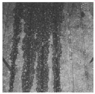
FIG. 1. A photograph of a cambered and grooved surface of an airport
runway. Note the degree of penetration between furrows as a low viscosity
solution of epoxy adhesive in acetone is poured on and drained away from
the surface .
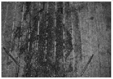
FIG. 2. Hairline curing cracks become visible as the solvent in FIG.
1 evaporates from the surface.
An illustration of hairline cracks caused by shrinkage of concrete during curing can be seen in FIG. 1 and FIG. 2. FIG. 1 is a photo graph of the cambered surface of an airport runway which as been grooved with a diamond saw to facilitate draining of rain water in an attempt to reduce hydroplaning of aircraft in wet weather. In this photograph a 50 percent solution of epoxy grout liquid (without aggregate) in acetone was poured on the surface of the runway. Note the degree of penetration into the concrete between furrows as the solution drains away. In the photo graph of FIG. 2 the highly volatile solvent has all but evaporated from the surface, exposing the wetted crack openings like a fingerprint. Before wetting with the solution, cracks were invisible to the naked eye. This condition exists in most concrete machinery foundations and is caused by water loss from the capillary pores in the concrete while curing. This water loss causes shrinkage which would not be experienced if the concrete had been immersed in water for 28 days like the samples from each pour that are usually sent to the laboratory for testing. While such shrinkage cracks do not constitute structural failure in machinery foundations, they do provide a path for the penetration of lubricating oils into the foundation.
One interesting fact was that cored concrete samples from this runway typically had 6,000 psi compressive strength.
It is good construction practice to seal the surface of a foundation with a good quality epoxy paint as soon as the forms are removed. This sealing of the foundation accomplishes two objectives. First, it seals in water and encourages more complete curing of the concrete, and second, it prevents penetration of lubricating oils into the foundation after start-up. This sealing is particularly important in areas such as around the oil pan trough which are usually flooded with oil. Paint will not usually stick to concrete unless the surface has been sandblasted to remove the laitance or unless a penetrating primer has been applied before painting. Some specialty coating manufacturers provide special primers for epoxy coatings when used on concrete. Most of these special primers contain either acetone or ketone solvents which are low in viscosity and water soluble. When utilizing these primers, care must be taken to prevent build-up of flammable vapors and breathing or contact with eyes or skin. Read the warning labels on the containers.
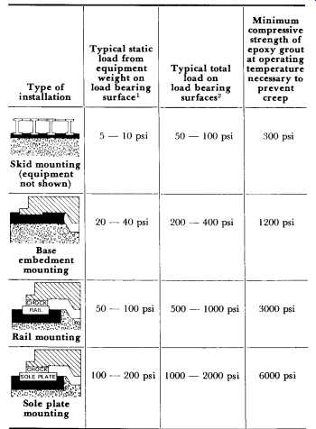
Table 2 Typical Loadings for the Various Methods of Installing Compressors
Methods of Installing Machinery
The four common methods of installing compressors in the order of increasing foundation load requirements are shown in Table 2. Static load ranges shown in the first column are relatively low compared with the strength of the supporting concrete. What complicates the situation is the combination of additional anchor bolt load, dynamic load and dramatically lowered epoxy grout strength due to rising temperatures.
Skid mounting is an equipment packaging concept whereby partial erection of the compressor and its related equipment are carried out under shop conditions where quality control can be closely monitored. This concept is ideal for equipment destined for offshore or remote locations where accessibility and accommodations are limited or where skilled man power is not available. Packaging works well on portable units in the lower horsepower range.
Job-site skid installation is progressively more difficult with increasing compressor size because of the number of structural members required.
Most packagers do not provide access holes to permit grouting of internal structural members. Those internal "I" beams anchored to the equipment above are critical. Consequently, with typical factory design, grout placement must be accomplished from the edges of the skid. Placement of grout prepared to the proper consistency is difficult and often the critical members are left unsupported. When this occurs, a suspension bridge effect is created, allowing excessive vibration to occur when the equipment is operating. The obvious solution to this grouting problem is to cut access holes in the field. This should be done only with the manufacturer's approval, since otherwise the warranty may be voided. After grouting, all access holes should be covered.
As mentioned earlier, most compressors leak oil. Because skids are fabricated by strip welding rather than seal welding, oil gradually seeps into the skid cavities. To reduce this fire hazard it is common to provide openings between cavities for oil drainage. With the usual inconsistencies in grout level, complete oil drainage is not possible. Oil degradation of cement grouts and concrete has long been recognized. With this in mind, skids which are to be permanently installed should be installed with epoxy grout. Bond strength of epoxy grout helps to anchor internal structural members that have no anchor bolts in the concrete.
The embedment method of installing machinery is by far the oldest method. For short crankshaft gas engine compressors in the middle horse power range, this method is preferred because it provides a "key" to resist lateral movement. On long crankshaft equipment in the higher horsepower range, thermal expansion of the foundation can cause crankshaft distortion problems. Foundation expansion is uneven due to heat losses around the outer periphery of the foundation and results in center "humping." The effects of humping can be avoided by installing the equipment on rails or sole plates. The air space between the foundation and equipment provides room for thermal growth without distorting the equipment frame. The air space also allows some heat dissipation through convection.
Exercise caution when installing equipment on sole plates-grout properties are taxed to the absolute maximum when sole plates are designed for static loads in the 200 psi range and then installed under equipment with high operating or oil sump temperatures. This is particularly true during the first few hours of operation until the grout passes through its period of secondary curing. Refer to the typical physical properties of epoxy grouts as shown in TBL. 3. Rails should be as short as possible and all rails and sole plate corners should be rounded to a 2-in. radius to minimize stress risers in the grout.
TBL. 3 Typical Physical Properties of Epoxy Grouts
In recent years there has been a concerted effort to replace steel chocks with epoxy chocks. This involves the use of liquid epoxy grout which is poured in place, and after curing, forms a nonmetallic chock. One of the advantages of this method of installing machinery is that it is not necessary to have a machined surface on the engine base in contact with the chock. This method of engine installation has been utilized for many years in the marine industry on diesel engines. The forces imparted by Diesel engines driving propulsion systems are quite different from the forces imparted by integral gas engine compressors. For example, in the Diesel engine propulsion system, the forces are primarily those involving torque as imparted by the crankshaft at the output end of the engine. In integral gas engine compressors, cyclic lateral forces, created primarily by the compressor stages, are involved. On some compressors, the lateral forces are so great that the engine base is fretted by steel chocks. It stands to reason that epoxy chocks would be much less abrasion resistant than steel chocks.
While there are numerous reports of "satisfactory installations" involving integral gas engine compressors on epoxy chocks, the fact is that this technique has not been utilized long enough to ascertain life expectancy.
The authors are not aware of any installations where the anchor bolts have been retorqued after several months of operation or where follow-up data have been taken from bench marks or other datum points such as tooling balls. In other words, the creep characteristics of epoxy chocks have not at this time been evaluated to the satisfaction of the authors. Further, some manufacturers do not provide test temperatures for the physical properties reported in their technical literature. Remember, the physical properties of epoxy grouts, unlike cement-based grouts, are reduced drastically with rising temperatures. Because of the lack of good data and experience, this method of installation should be classed as experimental and utilized only at the equipment owner's risk.
Anchor Bolts: Overview
The stretching of an anchor bolt between the bottom of the sleeve and the bottom of the nut (FIG. 3) is desirable to create a spring effect that will absorb impact without fatiguing when the bolt is tightened to proper torque. Isolating the bolt from the epoxy grout prevents bonding that can cause temporary stretching over a short section, resulting in loose bolts soon after start-up as the bond fatigues. Isolating the bolts also prevents short radius flexing of the bolt if lateral movement develops. Anchor bolts are designed for hold-down purposes and not as pins to restrict lateral movement.
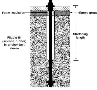
FIG. 3. A typical anchor bolt installation which allows freedom for
equipment growth from thermal expansion.
Original Anchor Bolt Installations
It is a standard practice to install anchor bolts in a foundation at the same time the reinforcing steel cage is fabricated and installed. Typically, the anchor bolts are located with the aid of a template created from engineering drawings. It should be a common practice to isolate the upper portion of the bolt with a sleeve. The purposes of the sleeve are twofold.
First, it allows stretch of the bolt during torque application. Second, it pro vides a degree of freedom for the anchor bolt, which compensates for minor positioning errors. The proper terminology for these sleeves is "anchor bolt sleeves." These sleeves are often, but incorrectly, referred to as "grout sleeves." As mentioned earlier, grout should never be placed in anchor bolt sleeves because bonding to the anchor bolt by the grout, particularly epoxy grout, prevents proper stretching and defeats the main purpose of the sleeves. The stretching of an anchor bolt between the bottom of the sleeve and the bottom of the nut is desirable to create a spring effect that will absorb impact without fatiguing when the bolt is tightened to proper torque. Bolt load should be calculated to prevent separation between the bottom surface of the nut and the machine boss when the bolts are subjected to operating forces, and in cases involving cyclic loading, to protect the bolt from fatigue effects of alternating tensile and compressive stresses.
FIG. 3 is a sketch illustrating proper anchor bolt installation.
Molded polyethylene sleeves are manufactured for the popular bolt sizes.
They are designed so the ends of the sleeve fit tightly around the bolt in order to center the sleeve, prevent concrete from entering the sleeve when the concrete foundation is poured, and, at the same time, prevent water, applied to the foundation for moist concrete curing, or rainwater from entering the sleeve.
After the concrete has cured, the surfaces to be in contact with grout are chipped away to expose the coarse aggregate. Immediately before positioning the equipment on the foundation, the upper end of the sleeve is cut off even with the top of the foundation and removed. Care must be taken to assure that water will not enter the sleeves and be allowed to freeze and crack the foundation, particularly on outdoor installations.
After the equipment has been positioned on the foundation, leveled, and aligned, the grout sleeves are filled with a pliable material such as a castable polysulfide-epoxy joint sealant or closed-cell polyurethane sleeve.
Filling the sleeve with a pliable material allows for movement and stretch, and at the same time prevents accumulation of lubricating oil in the sleeve after equipment startup. Lubricating oil, in time, will degrade concrete.
FIG. 4 is a photograph illustrating the cracking of a foundation at an anchor bolt, with the plane of the crack perpendicular to the crankshaft.
This crack was caused by grout being placed in the anchor bolt sleeve during original construction, thereby restricting movement of the bolt.
FIG. 5 shows the foundation after regrouting. The exposed portion of the anchor bolt was isolated with a tubular closed-cell polyurethane sleeve prior to repouring the epoxy grout. An expansion joint was installed to prevent new cracks from forming. After the grout has cured and the forms have been removed, the expansion joints and the outer periphery of the machine base where the grout contacts the boss are sealed with oil resistant silicone rubber. The silicone provides a barrier against infiltration of oil and other liquids into the foundation.

FIG. 4. A photograph showing foundation cracks at an anchor bolt. This
crack is in a plane perpendicular to the crankshaft.
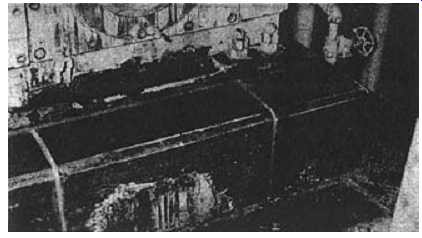
FIG. 5. Foundation after regrouting. Note the expansion joint at the
anchor bolt and that the outer periphery of the machine base has been
sealed with a fillet of silicone rubber.
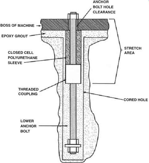
FIG. 6. Replacement anchor bolt.
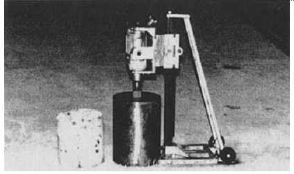
FIG. 7. Air-powered diamond coring machine used in replacing anchor
bolts without regrouting the machinery.
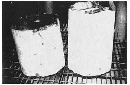
FIG. 8. Twelve-inch-diameter cores removed in the course of complete
replacement of an anchor bolt. Note the cross section of a No. 11 rebar
in the core.
Anchor Bolt Replacement
When anchor bolt failure is such that complete replacement is necessary, it can be accomplished using techniques consistent with the sketch shown in Figure 6. This sketch is of a typical replacement anchor bolt in an ideal installation. Complete replacement of an anchor bolt is possible without lifting or regrouting the machine. This is accomplished by drilling large-diameter vertical holes, adjacent to the anchor bolt to be replaced and tangent to the boss of the machine. Once the cores have been removed, access is gained to concrete surrounding the anchor bolt. After the surrounding concrete is chipped away, a two-piece and sleeved anchor bolt is installed. After the replacement anchor bolt has been installed, epoxy grout is poured to replace the concrete chipped from around the original bolt and to replace the concrete removed by the coring.
This procedure utilizes an air-powered diamond coring machine, as illustrated in FIG. 7. Because the machine is air powered, it can be used in hazardous environments without creating a danger from sparks of open electric motors. Further, because a lot of power can be delivered by small air motors, the size of the coring machine is relatively small. With proper gear reduction, a hole as large as 16 inches in diameter can be drilled with this machine. FIG. 8 shows 12-inch-diameter cores that have been removed with this machine. In the course of obtaining these cores, it was necessary to core through a No. 11 (1.375=-diameter) rebar, a cross section of which can be seen in this illustration.
FIG. 9 depicts a dual anchor bolt installation where both anchor bolts have been replaced and grouting is in progress. This picture was taken after the first pour of epoxy grout. Note that sleeving has not yet been installed on the upper stud above the coupling nut. Before the second pour was made, a split closed-cell polyurethane sleeve was installed to isolate the upper stud and coupling.
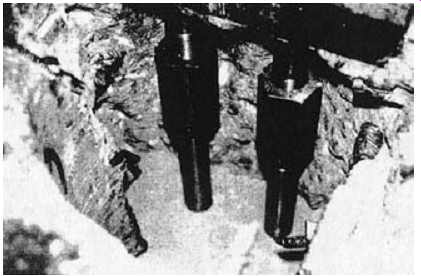
FIG. 9. Replacement of dual anchor bolts after the first pour of epoxy
grout. The isolation sleeving has not yet been installed.
Figure 10. Stresses at foundation corners caused by cyclic temperature.
Outdoor Installations
Because epoxy grout and concrete absorb and dissipate heat rather slowly, cyclic temperatures cause uneven thermal expansion or contraction. This unequal expansion produces unequal stresses. The weak link is the tensile strength of the concrete, and cracking occurs in the corners where stress risers exist (FIG. 10). In Condition A, the system is in thermal equilibrium and no stresses exist. During the cooling cycle shown in Condition B, the grout surface contracts first. This causes a thermal gradient within the grout which produces stress that promotes edge lifting.
As the temperature conditions are reversed during the heating cycle, as shown in Condition C, cracks have a tendency to close. As the cycle is repeated, cracking progresses until it reaches a point under the edge of the equipment where compressive loading exists. Because tension is required for cracking, cracking cannot continue into an area which is under compression. Thicker grout increases the tendency for cracking until the cross sectional dimensions of grout and shoulder are about equal. After grout thickness equals or exceeds the shoulder width, tendency for cracking is greatly reduced due to the inflexibility of this configuration. While cracking of this nature does not cause immediate operating problems, it does provide a path for oil to penetrate into the foundation. Over an extended period of time support will be diminished as oil degradation of the concrete proceeds.
Cracks of this nature can be virtually eliminated by utilizing one of the design techniques illustrated in FIG. 11. Solution A is based on the transfer of stress away from the corner. This technique also changes the stress from tension to shear. Solution B transfers the stress away from the corner to a shear area on the back side of the key. Solution C changes the usual cross section dimensions of the shoulder, making a relatively inedible configuration. Other designs, such as feather edging the grout, can be used, but all are based on eliminating stress risers at the foundation corners.
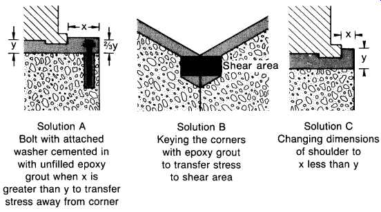
FIG. 11. Designs to eliminate stress risers in foundation corners.
Expansion Joints
The small differences in thermal expansion rates between concrete or steel and an aggregate-filled epoxy grout become increasingly important as the length of the grouted equipment increases. Cracking can be expected near regions of anchor bolts or at rail or sole plate ends, unless care is taken in the design to eliminate stress risers. This is particularly true during equipment startup or shutdown where a temperature gradient might be created or when brittle grouting materials are employed. For example, during startup of rail-mounted equipment, the rails begin to grow first as a result of thermal expansion because they are in contact with the equipment base and conduct heat well. In order to prevent rail growth, opposing forces must be created equal to the compressive strength of the steel in the rail. Such forces would be well over 50 times the tensile strength of the grout. If the grout has enough elasticity to allow rail growth without extensive cracking, it is probably too soft to maintain support without creep. The grout should have adequate compressive strength to maintain alignment without creep.
The obvious solution is to install expansion joints. Expansion joints, as shown in FIG. 5, can be cast into the foundation when the epoxy grout is poured. After the foundation has been dressed, the surface of the expansion joint and the outer periphery of the machine base is sealed with silicone rubber.
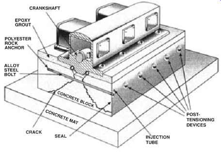
FIG. 12. Method of repairing compressor foundations that are cracked
parallel to the crankshaft.
Postponement of Regrouting Is Risky
Real or perceived economic conditions in industry encourage postponement of routine maintenance of operating equipment. As a result, machinery foundations fail at an increasing rate during these periods. The most serious type of failure is foundation cracking in a plane parallel to the crankshaft. These cracks may be caused by inadequate design or by operating conditions that exert excessive forces on the foundation. Unless these foundation cracks are repaired at the time of regrouting, grout life will be greatly reduced (usually to about 10 percent of its normal life).
Lateral dynamic forces are generated by compressor pistons and by some power pistons. Theoretically, if a machine were perfectly balanced, there would be no forces exerted on the foundation other than dead weight.
Under such a condition, there would be no need for anchor bolts. In reality, a perfectly balanced reciprocating machine has never been built. No experienced engineer would ever consider operating reciprocating equipment without anchor bolts.
After establishing the fact that unbalanced forces do exist on well designed and -maintained equipment, consider what happens when maintenance is postponed. Take the ignition system, for example. Everyone knows what to expect from an automobile with the engine idling after one or two spark plugs have been disconnected. Imagine the same circum-stances with a large industrial gas engine compressor running at 100 percent capacity. Next, suppose there are lubricating oil leaks that puddle on the foundation shoulder. If any movement exists between the machine and grout, oil will penetrate voids caused by the movement, and hydraulically fracture any remaining bond between the machine base and grout.
As movement between the machine and grout increases, forces exerted on the foundation increase at an exponential rate, because of change in direction and impact.
At 330 rpm there are 475,200 cycles per day. Over 20 years the foundation sees the stresses of 3.4 billion cycles. Most reciprocating equipment is expected to last more than 20 years.
The tensile strength of concrete is only about 10 percent of its compressive strength. Because of this weakness in tension, reinforcing steel is embedded in concrete to carry the tensile loads. The placement of rein forcing steel should be chosen with consideration as to the source and direction of the external forces applied to the foundation. According to this reasoning, the preponderance of reinforcing steel in a reciprocating engine/compressor foundation should be placed in the upper portion of the block in a direction perpendicular to the crankshaft. Weighting the placement of steel in this location would reduce the tendency for cleavage-type failures that sometimes begin at the top of the foundation in the notch below the oil pan and extend through the block to the mat below.
The notch provided in the top of a foundation for the oil pan creates a perfect location for stress risers. A moment is created by lateral dynamic forces multiplied by the distance between the machine base and the transverse reinforcing steel in the foundation below. The possibility of a foundation cracking at this location increases as the depth of the notch increases. The further the distance between the horizontal forces and transverse reinforcing steel, the greater the moment.
FIG. 12 illustrates a method of repairing such cracks by drilling horizontal holes spaced from one end of the foundation to the other end.
This series of holes is placed at an elevation of just below the oil pan trough. A high-tensile alloy steel bolt is inserted into each hole and anchored at the bottom of the hole. Next, a small-diameter copper injection tube is placed in the annular space around the bolt; the end of the hole is then sealed and the nut tightened to an appropriate torque to draw the two segments of the block back together. An unfilled or liquid epoxy is injected into the annular space around the bolt. Air in the annular space around the bolt is pressed into the porous concrete as pressure builds. After the annular space has been filled, injection continues, and the crack is filled and sealed from the inside out.
This repair method places the concrete in compression, which would otherwise be in tension. The compressive condition must be overcome before a crack could possibly reoccur. As a result, the repaired foundation is much stronger than the original foundation. This technique is often used when the concrete in the foundation is of poor quality.
Preparation of Concrete Surfaces Prior to Grouting
It has been estimated that 90 percent of the heavy equipment installed today on original installations was installed utilizing faulty grouting techniques. Because vibration and alignment problems with heavy machinery are solved (or should be solved) in the direction from the ground up, it is logical that grouting errors should be discussed beginning with surface preparation of the concrete.
Many early grout failures can be attributed to poor surface preparation of the concrete prior to grouting. Because the grouting problems associated with poor surface preparation are so widespread, it is obvious that few understand the difference between good and poor surface preparation.
The only good method of preparing a concrete surface prior to grouting is to chip away the surface with a chipping gun to expose coarse aggregate. This means at least a minimum of 1/2= to 1= of the surface must be removed. Poor methods of surface preparation include raking the surface of concrete prior to curing, intermittent pecking of the surface with a chip ping gun, sandblasting the surface after the concrete has cured, and roughening the surface with a bushing tool (a spiked potato masher). Distinguishing between good and poor concrete surface preparation requires an understanding of bleeding of fresh concrete pours and mechanisms involving hydration of cement. Bleeding of freshly placed concrete is a form of separation where water in the mix tends to rise to the surface. In the course of bleeding, some of the solid ingredients classify near the surface. Classifying of concrete ingredients is a form of sedimentation.
If the bleeding rate is faster than the evaporation rate, the rising water brings to the surface a considerable amount of the fine cement particles, along with any residual silt or clay that may have been present in the aggregate.
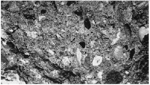
FIG. 13. Properly prepared concrete surface ready for grouting.
In the course of concrete mixing, some of the hard and adherent clay and silt coatings will be ground loose from the surface of the aggregate.
These loosened particles migrate to the surface of the concrete while the concrete is vibrated to gain proper compaction. The migration is enhanced by bleeding. This process promotes the formation of heavy laitance at the surface and results in a porous, weak, and nondurable concrete surface.
If the bleeding rate is slower than the evaporation rate, the water loss at the surface prevents proper hydration of the cement near the surface.
Improper hydration of the cement at the surface also results in a weak and nondurable concrete surface. Further, water loss while the cement paste is in its plastic state causes a volume change commonly known as plastic shrinkage. While 1 percent plastic shrinkage is considered normal, excessive water loss through evaporation leads to surface cracking. FIG. 13 illustrates proper chipping of a concrete surface prior to grouting. Note the fact that coarse aggregate has been exposed. Also note that the coarse aggregate is fractured in the process of chipping. Fracturing of coarse aggregate while chipping confirms the good bond of the cement to the aggregate. This observation is a good indication of quality concrete.
In summary, regardless of the bleeding or the evaporation rate, the concrete surface will be weak. The internal tensile strength of concrete can be estimated to be about 8 to 10 percent of its compressive strength. For example, the tensile strength of 4,000 lb concrete is usually 320 to 400 psi.
The tensile strength of concrete at the surface is only about 50 psi. Because of this weakness, the surface of the concrete must be removed prior to grouting if good bonding is expected.
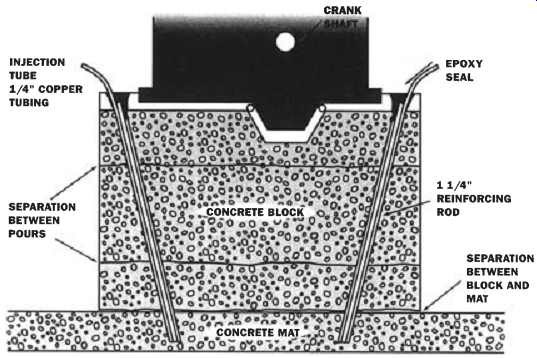
FIG. 14. Method of repairing compressor foundations where the block
has separated from the mat.
Repairing Failures Between Block and Mat
Until recent years, foundation failures on reciprocating equipment between the concrete block and concrete mat were a rare occurrence. At present, this type of failure is becoming more common. This increase in failures can be attributed to poorer construction practices and postponement of equipment maintenance. Before the concrete block is poured, the mat must be chipped to expose course aggregate. This is the only good method of removing the laitance from the surface of the mat and providing an anchor pattern between the block and mat. This requires chipping away at least 1/2= to 1= from the surface of the mat. Sandblasting, raking the concrete surface prior to curing, or roughening the surface with a bushing tool as a means of surface preparation is unacceptable. These methods do not remove all the laitance, nor do they expose course aggregate in the concrete.
Lateral dynamic forces are generated by most reciprocating equipment, and in particular with gas-engine compressors. Consider what happens when maintenance is postponed. One would certainly expect distress from an automobile engine with each cylinder operating at a different pressure because of blow-by from defective piston rings. Imagine the same circumstances with a large industrial gas-engine compressor running at full capacity. Next, suppose there are portions of defective grout on the foundation shoulder. If any movement exists between the machine and grout, ever-present spilled oil will penetrate voids caused by the movement, and hydraulically fracture any remaining bond between the machine base and grout. As movement between the machine and grout increases, forces exerted on the foundation increase at an exponential rate; they change their direction and impact billions of times over the life of the machine. Operating under these conditions ultimately results in foundation cracking, separation between the block and mat, or both types of failure.
FIG. 14 illustrates a method of repairing separation between the block and mat. Vertical, or near-vertical, holes are drilled through the foundation and into the mat. These holes are usually placed in the foundation around the outer periphery of the equipment. Next, rebar is placed in the holes along with an injection tube, and the entrance of the hole is sealed with an epoxy material. After the seal cures, the annular space around the rebar is pressure-filled with an epoxy liquid, and any cracks that the holes cross are then pressure-grouted from the inside out as pres sure builds. The curing of the injected epoxy completes the foundation repair.
Grouting Skid-Mounted Equipment
A skid is a steel structure, used as a shipping platform, that is subsequently installed on a concrete pad or foundation at the job site. This installation concept, most often called "packaging," allows the manufacturer to factory assemble a unit under shop conditions. Packages are frequently complete with accessories, instruments and controls. The cost of packaging is usually much less than would be required for field assembly, particularly where the job site is in a remote part of the world.
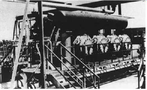
FIG. 15. A typical skid-mounted integral gas engine compressor complete
with accessories, controls, and instrumentation.
/images/mach-comp-repair_3-16.jpg
FIG. 16. Proper skid grouting.
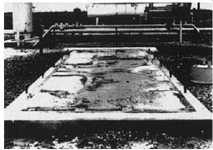
FIG. 17. Poor grout placement on a similar installation.
When the installations are temporary, and relocation of the equipment at a later date is anticipated, cement grouts are generally used. Because cement grouts do not bond well to steel surfaces, lifting the skid at a later date is relatively easy. On the other hand, when the installation is to be permanent, epoxy grouts are generally utilized. The advantage of an epoxy grout lies in the fact that it bonds extremely well to both concrete and steel. Epoxy grouts also provide an oil barrier to protect the underlying concrete foundation. Concrete exposed to lubricating oils over a long period of time can become severely degraded and lose all its structural properties.
A typical skid-mounted integral gas engine compressor is shown in FIG. 15. When proper techniques are carried out during the original installation, the grout should contact the entire lower surfaces of all longitudinal and transverse "I" beams. Complete contact is necessary in order to prevent vibration when the unit is placed in operation.
FIG. 16 shows a foundation pad where a skid has been removed leaving the cement grout intact. This photograph illustrates proper cement grouting. Note the impression left in the grout by the lower flange of the longitudinal and transverse "I" beams. Virtually 100 percent grout contact was obtained on these load-bearing surfaces.
FIG. 17 is an example of poor grout placement. Note the lack of support in the center where most of the machinery weight is concentrated.
Long, unsupported spans are an invitation to resonant vibration problems and to progressive sagging of the beams with age. Progressive sagging eventually causes continual misalignment problems. Further, the anchor bolts on the compressor side of the crankcase are attached to one of the internal longitudinal beams. When the equipment is at rest, there may be perfect alignment; however, when the equipment is running, the beam may be flexing much the same as a suspension bridge. If this is true, fatigue of the crankshaft and bearing damage may result.
The obvious solution to this defect is to grout-in the unsupported sections. Since cement grout will not bond well to itself or concrete, any regrouting should be carried out with an epoxy grout because of the inherent bonding properties of epoxies. Some epoxies will even bond to oily surfaces.
Grouting of Oil-Degraded Concrete
In establishing guidelines for the use of epoxy materials on oil saturated concrete, the expected results should be compared with the properties of good concrete because these were the criteria invoked when the installation was originally designed.
The compressive strength of good concrete will vary from 2,500 to 7,000 psi depending upon its cement content, curing conditions, etc. The internal tensile strength should be about 8 to 10 percent of the compressive strength or 200 to 700 psi. The tensile strength at the surface of formed concrete may be as low as 75 psi and the surface of a steel troweled floor may be as low as 50-100 psi due to laitance on the surface.
Consequently, good surface preparation must be carried out before a satisfactory bond of epoxy to concrete can be obtained.
Experience has definitely shown that the best method of preparing a concrete surface for bonding is through mechanical scarification to remove surface laitance. This scarification can be accomplished by chip ping away the surface, sandblasting or grinding in this order of preference.
At one time acid washing was widely respected as a means of surface preparation, but this practice has not proved reliable. When contaminants, such as oil or grease, are present, special consideration should be given to surface preparation and epoxy thickness.
Although concrete can absorb oil, the process is, fortunately, relatively slow. Once oil has been absorbed a gradual degradation in both tensile and compressive strengths will follow and given enough time the compressive strength of the concrete may be reduced to the point where it can be crumbled between the fingers. Preventive measures, such as sealing the concrete with an epoxy sealer to provide a barrier, can avoid this problem.
This is usually done at the time of original construction. Remedial measures can also be used once the problem has occurred. Most of these remedial techniques involve surface preparation, patching, or transfer of loading.
The importance of epoxy grout thickness is better understood when it is recognized that in solid materials, forces resulting from compressive loading are dispersed throughout the solid in a cone-shaped pattern with the apex at the point of loading. In tensile point loading the force pattern is such that, on failure, a hemispherically shaped crater remains. Consequently, the weaker the concrete, the thicker the epoxy covering should be in order that loading can be sufficiently distributed before force is transferred to the concrete. For example, a severely oil degraded foundation may be capped with a thick layer of epoxy grout in much the same manner as a dentist caps a weak tooth. If you can contain a weak material, you can maintain its strength.
There have been many repair jobs with epoxy grout on foundations of reciprocating machinery where oil degradation was so severe that it was impossible to remove all oil-soaked concrete before regrouting. In such cases, regrouting can sometimes be done with the equipment in place.
Such repairs are accomplished by chipping away the oil grout from the foundation shoulder and as far as one-half of the load bearing area under the equipment. It is important that enough grout remain to support the equipment while repairs are being conducted. The advantage of removing some of the old grout under the equipment is to provide a structurally sound area after repairs, equivalent to that supporting area which would be available had the equipment originally been installed on rails or sole plates. Once this is done, the equipment can be pressure-grouted as discussed later in this section. Enough concrete is removed to round off the shoulders to a cross-sectional radius of 1 1/2 to 2 ft. Then vertical holes can be drilled into the exposed concrete with a pneumatic rock drill. Usually these holes are placed two ft (about 60 cm) apart and are drilled to a depth to provide penetration through the remaining oil-soaked concrete and at least two ft into the undamaged concrete below. In addition, holes can be drilled in the remaining part of the foundation shoulders at such angles so as to cross below the oil pan at an elevation of approximately two to three ft below the pan or trough. Afterward, additional horizontal reinforcing steel can be installed and wired to the vertical members which were earlier cemented into the good concrete with an epoxy adhesive. The purpose of the new reinforcing steel is to transfer as much load as possible to an area where the concrete was unaffected by oil degradation. (cont. part 2)