Some basic facts--Ultimate Guide to Troubleshooting & Repairing Microwave Ovens
| HOME | Troubleshooting | DIY Tips |
|
← → Before long, nearly every home will have a microwave oven. Right nosy microwave ovens are selling all over the United States, and nearly every major appliance manufacturer is building them. Once you own a microwave oven, you cannot do without it, just as you cannot do without a TV Although microwave ovens might not require the same amount of service as a TV set, they do break down like any other electronic/mechanical device ( fgr. 1). The microwave oven is an electrical appliance that is designed to warm or cook food within minutes or even seconds. Power is applied to the magnetron tube after a sequence of buttons, switches, and other components are energized. The magnetron tube radiates RE energy that is tunneled into the oven to quickly cook the food that has been placed in the oven cavity. 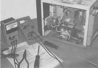
Fgr. 1 Like all mechanical-electronic devices, microwave ovens break down. Different types of ovens: Today, the microwave oven is found wherever food is prepared and served. Small, compact ovens (450 watts or less) are used in trailers, motor homes, and small apartments ( fgr. 2). A standard tabletop microwave oven with 600 to 800 watts of power is found in most homes. Some of these tabletop ovens combine a separate ac heater coil for cooking and are referred to as convection ovens. Many large microwave ovens have a carousel or glass rotating dish that provides even heat in all areas. Large commercial microwave ovens are found in restaurants, hospitals, and nursing homes. The compact oven: The small microwave oven is generally used for on-the-road cooking. It can be easily transported in the trunk of a car, trailer, or motor home ( fgr. 3). These ovens perform only basic oven functions such as warming up food and drinks or light-meal cooking. Often, these units are less than 450 watts and pull less current than the larger models. They operate at the same frequency (2450 MHz) as most microwave ovens. General Electric drop-door oven: General Electric has a Profile line with a built-in combination/convection microwave oven. The JEBC200W model is white-on-white, and the JEBC200B model is black-on-black. These ovens feature an integrated exterior appearance, which eliminates the need for built-in trim kits when building them into matching cabinets. 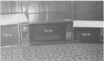 Fgr. 2 Microwave ovens can be used in the kitchen, cottage, or mobile home. The new microwave ovens have a drop-down front door with a horizontal handle that matches the appearance of standard wall ovens to create a complementary appearance in the kitchen. You can purchase a regular microwave oven (without the convection oven) in models JEB100W (white-on-white) and JEB100B (black-on-black). Samsung MW5510 and MW2500 models: The 800-watt Samsung microwave oven has a 1.0-cubic-foot auto-weight defrost system. With the automatic defrost feature, simply program the weight of the food, and the oven will automatically determine the correct cooking time. This MW5510 model also features a popcorn key, auto heat, one-touch cook, and ten power levels. The Samsung touch-control microwave oven (MW2500) has. a defrost feature for quick cooking right from the freezer. The oven has a two-stage cooking system and the glass tray can be removed for easy cleaning. Sharp R3A54 12 instant action keys: The Sharp R3A54 microwave oven has three keys in four separate lines to provide easy selection to twelve instant action keys. The first three buttons are popcorn, pizza, and beverage cooking keys. The other key buttons are baked potato, fresh vegetable, rice, dinner potato, pasta, muffin, main dish, vegetables, and roll muffin. Good-bye guesswork! Popcorn, baked potato, and ten other favorite foods have their own designated keys. This oven also has an Express Defrost feature and a Minute Plus key that sets the oven on high for one minute per touch. 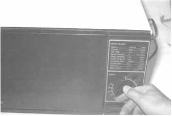 Fgr. 3 Small microwave ovens operate with less than 450 watts. Microwave oven frequency: Microwaves are electromagnetic waves of energy. They are similar to light, radio, and heat waves. Microwaves have many of the same characteristics as light waves. They travel in a straight line and they can be generated, transmitted, reflected, and absorbed, hi a microwave oven, the magnetron tube generates the microwaves. They are transmitted to the oven cavity, reflected by the sides of the oven area, and then absorbed within the food that is cooked in the oven cavity. The microwave wavelength is relatively short compared to light. The frequency of a microwave oven is 2450 million cycles per second, with a wavelength of under 5 inches. There are three frequency bands allotted for microwave operation by the Federal Communication Commission. They are at 915 MHz, 2450 MHz, and the highest one, 5500 MHz. Today, almost all microwave ovens operate at 2450 MHz. The magnetron tube generates the cooking energy in a microwave oven. Materials with a high moisture content (like most foods) absorb microwave energy. The food is made up of millions of molecules per cubic inch, which align themselves with the microwave energy when it enters the food. The microwaves change polarity every half cycle and oscillate back and forth at 2450 MHz, creating friction. The friction between the molecules converts the microwave energy to heat and in turn, cooks the food ( fgr. 4). 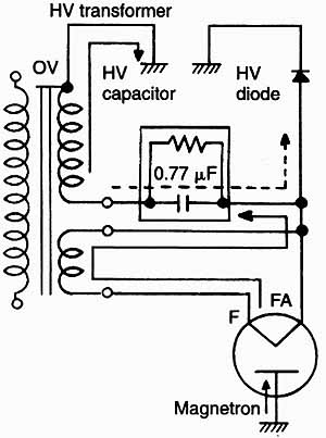 Fgr. 4 The magnetron supplies the RF energy needed to cook food. HV transformer Microwaves can be reflected in the same manner as light. These short electro magnetic waves of HF energy pass through material such as glass, china, paper, and most plastics. Materials such as aluminum foil and stainless steel tend to reflect the microwaves, while ordinary steel might absorb some microwave energy. Metal material placed in the oven cavity should be used only as recommended in the cooking instructions. The sides of the oven cavity are constructed of metal so as to remain cool while the food is cooking. Although the sides and bottom of the oven sometimes feel warm, this is caused by the transfer of heat from the food. The front door, which contains a metal plate with perforated holes, remains cool. The holes reflect the microwaves but allow light to enter so notice inside the oven cavity. Remember: Water absorbs microwaves and begins to boil, while light passes through water. Food prepared in a microwave oven should be cooked all the way through and not from the inside out. In some ovens, the food must be cooked for a few minutes, turned, and cooked again. Other ovens have a device that rotates the food, providing for even cooking throughout. With all food preparation and cooking, you should al ways follow the oven manufacturer’s instructions. Fundamental function of the magnetron: The cathode is located in the center of the magnetron. It’s a filament that boils off electrons when it’s hot. The cathode is connected to the negative side of the power supply, which has a potential of approximately 4000 volts with respect to the anode, which is connected to the positive side. The 4000-volt potential is produced by means of the high-voltage transformer and the doubler action of capacitor and diode, of which a detailed circuit description is given later in this guide. The electrons have negative charges, which means they are strongly repelled by the negative cathode and attracted to the positive anode. The electrons would travel straight from the cathode to the anode if the 4000-volt potential was the only force acting in the magnetron ( fgr. 5). However, the magnetron is a type of diode with a magnetic field applied axially in the space between the cathode and anode by means of two permanent magnets ( fgr. 6). If a magnetic field of sufficient strength is applied between the cathode and the anode, an electron will travel in a path almost at right angles to its previous direction, resulting in a circular motion of travel to the anode ( fgr. 7). Eventually, it reaches the anode. 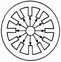
Fgr. 5 Electrons inside the magnetron travel from the cathode to anode. 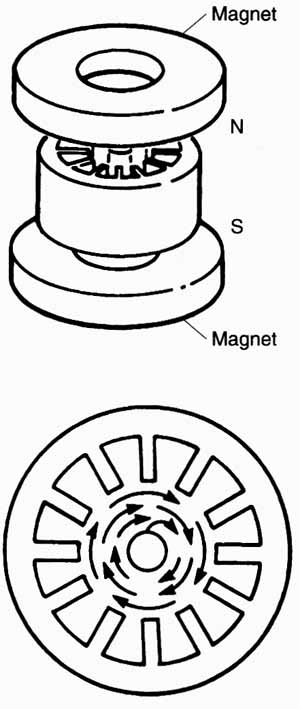
Fgr. 6 Heavy magnets are found within the magnetron tube. Fgr. 7 Electrons leave the cathode and travel in a circular motion to the anode element. Matsushita Elect. This circular motion by the electrons induces alternating current in the cavities of the anode. When an electron is approaching one of the segments between two cavities, it induces a positive charge in the segment ( fgr. 8). As the electron goes past and draws away, the positive charge is reduced while the electron is inducing a positive charge in the next segment. This inducing of alternate currents in the anode cavities can be thought of as a lumping together of the resonant circuit ( fgr. 9). In the actual operation of the magnetron, the electrons crowd together as they go around. Influenced by the forces of high voltage and the strong magnetic field, they form a spoke-wheel pattern (fgr 10). This crowd of electrons, which has much stronger energy than a single electron, revolves around the anode and eventually reaches the cavities, resulting in the continuous oscillation of the resonant circuits. The high-frequency energy, produced in the resonant circuit (cavities), is then taken out by the antenna and fed into the oven cavity through the waveguide ( fgr. 11). Some do’s and don’ts for safety: To prevent the risk of burns, fire, and electrical shock, the owner or operator should observe the following guidelines: When electrons approach one of the segments between cavities, a positive charge is induced. 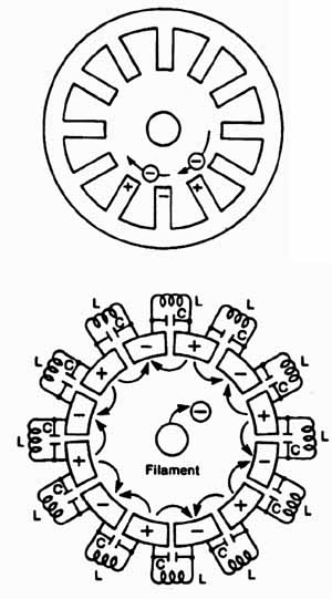
Fgr. 9 The resonant circuits are lumped together. Follow the microwave oven instructions before attempting to cook. Don’t forget that the oven is a high-voltage, high-current appliance. You must take extreme care at all times, but this does not mean that you have to be afraid to operate the microwave oven. Make sure that the oven is installed properly. Most ovens include a three-prong plug. You can pick one up at your local hardware store or electrical dealer ( fgr. 12). Don’t under any circumstance cut or remove the third ground prong from the power plug. The small, flexible grounding wire with a spade lug should be screwed under the plate screw of the ac outlet. Use a voltmeter to determine if the center screw of the ac receptacle is grounded. Install a separate outlet from the fuse box for the microwave oven. 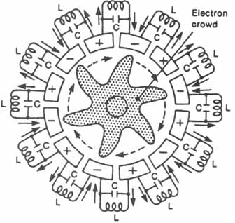
Fgr. 10 The strong magnetic force represents a spoked wheel pattern. Heaters; Mounting bolts; Metal leakage ring 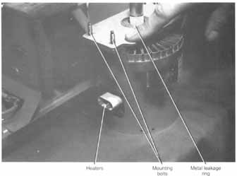
Fgr. 11 A magnetron tube is found in all microwave ovens. 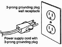 Fgr. 12 Make sure the ac plug and three-prong plug are grounded. Power supply cord with 3-prong grounding plug. 3-prong grounding plug wall receptacle. Don’t use an ordinary two-wire extension cord to operate the oven. If you need an extension cord, contact a local electrician or the appliance dealer that sold you the oven. Make sure that the ac power outlet is never less than 105 volts or more than 125 volts for proper oven operation. The microwave oven is designed to operate from 115 to 120 Vac. Don’t just plug the oven into an overloaded outlet where several appliances are already tapped into it. If you do, the oven might operate erratically and never cook properly. Install or locate the oven only in accordance with the installation instructions. Don’t install the oven where the side or top opening might be blocked. The hot cooking air must escape, and fresh air must be pulled into the oven for normal operation. Don’t operate the microwave oven if the power cord or plug is damaged. Repair the three-wire cord, and be sure that the ground wire is intact. Check the continuity from the metal cabinet to the ground wire terminal with the low range of an ohmmeter. Supervise children who are operating the oven. Most microwave oven problems are related to improper oven operation. Don’t use the oven outdoors. Don’t let the cord hang over edges of a table or the cooking counter. Keep the ac cord away from heated surfaces or a nearby cooking stove. Don’t use metallic cooking containers. Use only cooking utensils or accessories of the type recommended by the manufacturer or microwave cookbooks. Don’t use any type of material that might explode in the oven. Some sealed glass containers or plastic jars might build up pressure and explode. A regular paper sack with food inside might explode and cause a fire if steam or air holes are not punched in the top of the sack. A fire inside the oven might cause the plastic heat shields and front oven coverings to melt. This could result in a fairly expensive oven repair. Keep the oven cavity area spotlessly clean. Cooking fatty items such as bacon might in time cause grease to collect behind the plastic shelf supports on plastic microwave guide covers, resulting in excessive arcing and damage. Don’t operate the oven with nothing in it. Use liquid window cleaner or a very mild detergent with a soft, clean cloth over the oven’s face and interior surfaces. Don’t use any kind of commercial oven cleaner inside the oven area. Use a paper towel or sponge to blot up and remove spills while the oven is still warm. Pull the oven’s power cord out if fire is discovered inside the oven cavity. Keep the oven door closed to help smother the fire. Clean out the top area or exhaust areas for signs of food pulled up by the fan ( fgr. 13). Have the service person brush out these areas when the oven is serviced. A collection of food particles might in time cause a persistent odor. Some odors can be eliminated by boiling a one-cup solution of several tablespoons of lemon juice dissolved in water in the oven cabinet. Don’t change the operation of the oven while it’s in operation. This is a good way to blow the fuse of a microwave oven. Touch the stop button and start the operation all over again. Don’t assume that the microwave oven is defective if lines are streaking across the face of a TV set in a nearby room. Most ovens cause some type of interference to nearby TV receivers. When the microwave oven fails, make sure that the three-prong cable plug is in stalled in the ac outlet. Plug in a lamp or radio to make sure that the outlet is alive. Go over the operation instructions very carefully before calling the service person. Caution: It’s possible to receive a dangerous shock or possibly be killed by trying to just change the 15-amp fuse. The highly charged capacitor must first be discharged before touching any electrical or electronic component ( fgr. 14). Don’t remove the back cover of the microwave oven unless you know what you are doing. Keep the power cord pulled when the back cover is off. Oven installation: Make sure that the oven is located on a firm table base to prevent vibration. The oven should be installed with at least a 2- or 4-inch clearance on all sides of the oven cabinet. Of course, this depends on where the oven vents are located. Leave at least one inch or more clearance at the top of the oven. 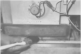 Fgr. 13 Clean out bread crumbs, dust, and food particles from the exhaust fan area. 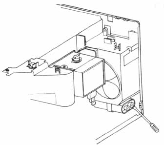 Fgr. 14 Always discharge the HV capacitor before attempting to change the fuse. Try to avoid installing the oven near a heat source, heat duct, or cooking range. Keep the oven out of the sun where temperatures might exceed 110°F. A microwave oven won’t operate if it’s too hot. Avoid using the microwave oven when the humidity is very high. Position the oven away from radios and TVs; the microwave oven might interfere with the reception. A microwave oven will operate successfully when adequate electric power is supplied to it. It’s best to install a separate outlet for the oven. Because the oven is protected with a 15-amp fuse, additional appliances on the same circuit might over load the circuit and blow the house fuse ( fgr. 15). 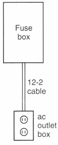 Fgr. 15 A microwave oven should be in a separate circuit with at least number 12-2 cable. Outlet; box All ovens should be grounded for personal safety. A three-prong plug is used to supply power arid ground the metal oven cabinet. Make sure that the third prong of the two-prong standard outlet is grounded. If installed by the appliance dealer, have the oven checked for proper grounds or have it checked by a local licensed electrician. While the electrician is present, have the power outlet checked for proper fuse protection and correct operation voltage (115 to 120 Vac). Service technician cautions and warnings: The microwave oven is a high-voltage, high-current piece of equipment, so you must use extreme care while servicing it. Before taking off the back cover or outside wrap, remove your wristwatch. Make sure that the oven is unplugged at all times when replacing and testing components. Never stick a tool or your hand inside the oven while the oven is operating ( fgr. 16). Before checking any component or wiring in the oven, discharge the high-voltage capacitor—just like you discharge the CRT anode connection before working around the high-voltage section of a TV. The big difference between the high voltage of a TV receiver and a microwave oven is the amperage; you might be severely shocked or killed if the high-voltage capacitor is not discharged. Always discharge the capacitor with an insulated-handle screwdriver before working in the high-voltage area. Make sure that the oven is properly grounded before attempting to service it. If you’re not certain, clip a flexible wire from a water pipe or fuse box to a metal screw on the back cover or metal chassis. Don’t use a regular two-wire extension cord to operate the oven while servicing. The microwave oven should not be operated with the door open. Don’t for any reason defeat the interlock switches. Check and replace all defective monitors and latch switches if the oven won’t shut off with the door open. The oven should never be operated if the door does not fit properly against the seal. Check for broken or damaged hinges. Visually inspect the seal gasket for possible cut or missing pieces. Check the gasket seal area for foreign matter. Make sure the oven door is mounted straight and fits snug against the oven. Readjust the door when play is felt between door and oven. Always remember to check all interlock switch functions before the oven is returned to the customer. While servicing a microwave oven, it’s best to have the service bench away from the customer and not to talk to anyone while working on the oven. Outside distractions might cause you to make a mistake that could result in an injury. Always keep your hands out of the oven operation area when the oven is operating. 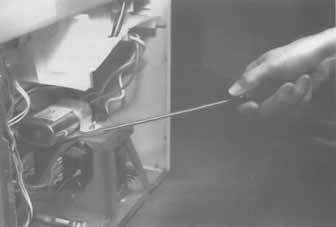 Fgr. 16 Don’t stick tools inside the oven while operating. After making any repairs or service adjustments, check the oven for excessive radiation. To ensure that the oven does not emit excessive radiation and to meet the Department of Health and Human Services guidelines, the oven must be checked for leakage with an approved radiation meter. Especially check for radiation around the door and vent areas. If by chance the radiation leakage is greater than 5 mW/cm or someone has been hurt pertaining to microwave radiation leakage, report this to the oven manufacturer. Although a few components can be substituted, most microwave oven parts should be replaced with the original part number. These can be obtained from the manufacturer or oven distributors. When replacing control panel circuits, don’t touch any part on the board, as static electricity discharge might damage the control. Usually these controls come packed in a static-free wrap and carton. Basic service precautions: When servicing any microwave oven, there are several basic safety precautions to follow: Microwave oven door: Don’t try to operate the oven with the door open, an improper seal, and/or dam aged door hinges. If the oven has been dropped, inspect the door, seal, and hinges before you do any other servicing on it. Make sure that the door closes properly and no foreign matter is inside the door. Extension cords: Always make sure that the oven is grounded with a three-prong-plug wall receptacle. Use only a three-wire extension cord between oven and wall outlet. It’s best to have a competent electrician install the three-prong wall receptacle. Unplug oven: Never reach into the oven component area while the oven is operating. When making ohmmeter or continuity tests, unplug the oven from the ac power line. If ac voltage measurements are to be made, clip on the voltmeter while the oven is off. Don’t touch the voltmeter test probes while the oven is plugged in. Shorting capacitor: Before checking any components in the oven, short out the two capacitor terminals. Always discharge the capacitor each time the oven is energized. Failure to discharge the capacitor could result in severe electrical shock. Door interlock switches: Don’t defeat or bypass the interlock door switches. Each interlock should be checked for proper operation. High-voltage section: The power transformer, capacitor, diode, and magnetron tube can contain high voltage (HV) when the oven is operating. When the oven shuts off, discharge the HV capacitor before attempting to do any type of service. Be careful when taking high voltages in the RV section. Magnetron tube: Check the magnetron level and secured bolts to eliminate hot spots or radio frequency (RF) arcing. Always replace the RF gasket found around the magnetron tube antenna. Don’t use metal tools near the magnetron, as it can jerk them out of your hands. Microwave leakage tests: Always make a microwave leakage test with the approved radiation meter after all repairs are made. This should be done before oven front and aide cleanup procedures. Checking the outlet receptacle The microwave oven should have a separate outlet and be protected with a 20-amp fuse. The outlet should be polarized and grounded. An improper ac outlet might provide electrical shock for the operator. Check the ac outlet for correct ac voltage (117-120 Vac) ( fgr. 17A). Determine if the left side of the outlet is grounded ( fgr. 17B). If the ac receptacle is wired correctly, the right side of the outlet should be hot ( fgr. 17C). Pull the plug: Always remember to pull the plug or cord before attempting to service the oven ( fgr. 18). Each time the oven is fired up, pull the plug and discharge the HV capacitor before putting your hands in the oven. Pull the plug before clipping test equipment to components in the oven. Pull the plug before taking continuity or resistance measurements of oven components. If by accident you are shocked by the HV capacitor and you end up with a metallic taste in your mouth, you will know how careless and how lucky you are. Installing the ac cord: Try to replace the ac power cord with the original part number. This way, every thing fits and is easily installed. If the new cord is to take some time or is not avail able from the manufacturer, check for heavy cord and a plug replacement at the local hardware store. You can replace the cord with a three-wire number-12 cable wire. Replace the ac plug with a heavy-duty, rubber, three-prong ac plug. 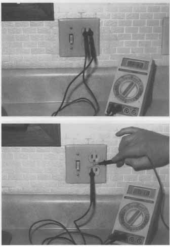 Fgr. 17B Check for a good ground and measure ac voltage between negative terminal and ground screw. Fgr. 17A Check the ac plug for at least 120 Vac. 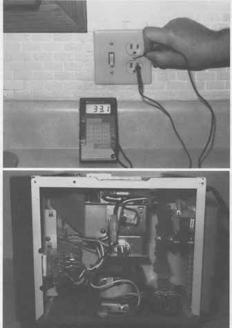
Fgr. 17C Check the ac plug for correct polarity. Fgr. 18 Pull the ac cord before attempting to service inside components. Make good, solid connections inside the oven area. Use crimp-on or eyelet connections. If these are not available, twist the copper braided wire into a small circle, to just fit over the bolt connections. Solder the entire eyelet or circle with a heavy- duty soldering iron for good, strong connections. Tie a knot in the cord, inside the oven, and wrap excess tape around the cord so it cannot be pulled out of the oven. Or use a cable clamp from the original cable, if it had one. Checking defective power line cords: Periodically, inspect the microwave oven ac cord for breaks, check marks, frayed areas, and broken ac plug connections. The original ac cord has a molded ac plug with an extra ground wire. Sometimes, when the cord is yanked or the unit is dropped, the internal cable wires might break inside the molded plug without any sign of breakage. Cut off the cord three inches from the plug and install another heavy-duty three-prong ac plug. Check the ground and both ac wires with the low ohm scale of the VOM or DMM. Make sure the green or ground wire has good continuity from the large center prong to the oven metal case, inside the oven. No resistance should be measured between these two areas ( fgr. 19). 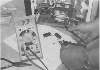
Fgr. 19 Check the ground plug from cord to metal base of oven. Lightning protection: Many new microwave ovens have metal oxide varistors in the power line to protect the oven from lightning and power line surges ( fgr. 20). These oxide varistors can be added to ovens that don’t have this type of protection. Solder in the oxide varistors at the power cord fuse terminals inside the oven ( fgr. 21). Even after you do that, a heavy line voltage surge or lightning a block away can cause the varistor to arc over and blow the oven fuse. Check the house fuse if the varistor and main fuse are blown. 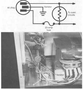
Fgr. 20 Check the oxide varistor to protect the touch panel control in the microwave oven. 20-amp fuse, ac plug. Fgr. 21 If the fuse keeps blowing, suspect a defective varistor. Basic oven components: Some microwave ovens have different basic oven components than others. All microwave ovens operate basically the same, except that some ovens have many additional features. Here is a list and brief description of most of the components found in a microwave oven. Antenna/antenna motor: The antenna and antenna motor are located below the removable glass floor in the GE JEBC200 built-in microwave oven. Remove the glass shelf (with a suction cup or putty knife) and lift the antenna off the antenna motor shaft. To service the motor, disconnect the power and remove from the wall. Remove the antenna. Carefully place the oven on its back on a comforter or pad. Remove 2 screws to access panel on bottom of oven. Disconnect the motor lead and the 2 screws that secure the motor ( fgr. 22). 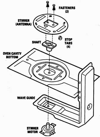
Fgr. 22 The antenna and antenna motor stir the microwaves to produce even cooking. FASTENERS; STIRRER; OVEN CAVITY; BOTTOM; STARTER MOTOR; 120 Vac Bleed resistor: The bleed or bleeder resistor is around 10 megohms. It’s found across the hv capacitor. When the oven is turned off, the bleed resistor discharges the capacitor within one minute ( fgr. 23). Always discharge the HV capacitor before working inside the oven. 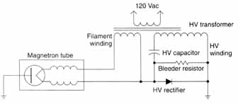
Fgr. 23 The bleeder resistor discharges the HV capacitor after the oven is shut off. HV transformer. Filament winding; Magnetron tube; HV; HV rectifier Blower motor: The blower motor draws cool air through the blower intake and is directed at the magnetron tube. Heat develops within the magnetron tube, and the tube needs to be kept cool with the blower fan blades. Most of the hot air is exhausted directly through the vents of the back plate ( fgr. 24). Buzzer or speaker: The buzzer or speaker is used in ovens with the power control circuits to indicate when the cooking process is finished. The audio device is located on the control circuit board ( fgr. 25). 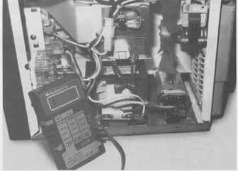
Fgr. 24 The fan blower brings cool air across the magnetron tube to keep it from overheating. Capacitor The oil-filled capacitor is located in the HV doubler circuit ( fgr. 26). The ac voltage (2500 V) from the power transformer charges the capacitor through a silicon diode increasing to approximately 4000 peak volts. Always remember to discharge the two capacitor terminals before attempting to check or replace any component in the oven-operating area ( fgr. 27). Cavity light: The cavity light is located in the middle of the oven behind the top front grille. Disconnect the ac plug. Open oven door and remove two screws underneath grille lip. Remove screw holding light bulb housing ( fgr. 28). Lift up on the door over hang and rotate the bulb housing towards the front of the oven. Unscrew and replace the 40 watt light bulb (WB02X4253). Cook relay: The cook relay, when energized, closes the ac circuit so that the voltage is applied to the primary terminals of the power transformer. Sometimes this relay is referred to as the power relay. Cook switch: Usually the cook switch is the last component to be punched after the oven set tings. The cook switch completes the circuit to the power transformer. A relay might be energized by the cook switch, or the power transfer is completed through timer contacts, thermal cutout, and primary interlock switch. 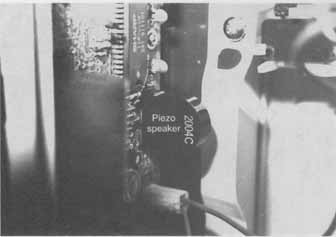
Fgr. 25 The piezo speaker or buzzer indicates when cooking is finished. HV capacitor 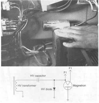
Fgr. 26 The HV capacitor operates in the MV doubler circuit. Fgr. 27 The HV capacitor is in series with the HV diode and common ground. Magnetron; HV transformer; HV diode Control circuit: The control circuit might consist of an electronic control board mounted behind the front control panel. In some ovens, the control circuit is called the electronic controller. You might find that both the front panel and the control circuit board are replaced as one unit ( fgr. 29). Convection fan: The convection fan and heater are located at the rear of the GE JEB oven. There are two blades on the convection motor shaft, one moves the air across the heater (internal blade) and the outside fan is used to cool the fan motor ( fgr. 30). 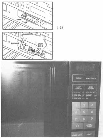
Fgr. 28 The cavity light provides light inside the oven. Fgr. 29 The control panel consists of key buttons, an LED or tube display, control components, and a ribbon cable. Remove the convection fan motor by removing top panels and discharging the fly capacitor. Remove the screws that hold the fan blade in position. Remove the four screws that are located inside the heater element. Remove three screws at the other end of assembly. Now remove the two screws holding the motor to the motor bracket. Damper door motor: The damper door motor and assembly is located next to the magnetron tube at the back right rear of the GE JEB200 oven. The damper door is closed during cooking functions because the magnetron fan motor is always running when the oven is on. This allows for more cooler air to be blown into the oven cavity ( fgr. 31). 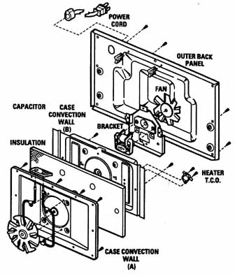
Fgr. 30 The convection fan removes hot air from the microwave oven. OUTER BACK, CAPACITOR CASE CONVECTION, INSULATION, HEATER, CASE CONVECTION. (A) MOTOR Defrost switch: The defrost switch is normally closed and allows the circuit to be completed for normal operation. The defrost circuit is made up of the defrost switch, defrost timer switch, defrost motor, and CAM. Placing the defrosting lever in the ON position opens the normally closed defrost switch and completes the circuit through the defrost timer switch. Defrost timer switch: The defrost timer switch is opened and closed by the CAM attached to the mo tor shaft. Actually, the defrost timer switch is in parallel with the defrost switch ( fgr. 32). The defrost and timer switches are similar to the van-switch in other microwave ovens. 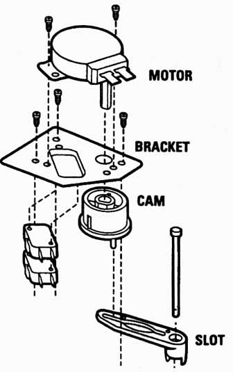
Fgr. 31 The damper door motor operates a door that opens during microwave cooking and closes during convection operations. Defrost motor: 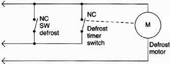
Fgr. 32 The defrost timer switch opens and closes the defrost switch. Door— GE lay down The lay down door in a GE JEBC200 consists of a handle, outer glass, sub-door assembly, choke cover, hinge assembly and latch pawls. Like several of the new ovens, the front door unlatches from the top and lays down towards the operator. The glass, handle, latch pawls, and door spring can be removed and replaced individually ( fgr. 33). Door seal: The primary door seal is sometimes called a choke. A choke cavity reflects the microwaves back into the oven cavity. The choke cavity is filled with a material called polypropylene, which is transparent to microwaves. Door latch: The door latch is an electrically operated mechanical device that prevents the door from being opened when the oven is in operation. The door might remain latched until the electrical circuit is interrupted. In some units, the door latch is made of solid cast material or it might have a plastic spring-operated latch assembly. Heater thermal cut-out: The heater TCO (thermal cut-out) is located on the back wall next to the convection motor. This safety device is responsible for not allowing runaway convection heater temperatures. If the oven gets too warm with convection heating unit on, the TCO will remove ac voltage from the heater coil. Heating element: A separate heating element might be used for browning and cooking food in some microwave ovens. The heating element is located at the top of the oven cavity. The heating element might be controlled with the temperature control unit ( fgr. 34). Interlock switches: You can find from two to five interlock switches in the various microwave ovens. Primarily, the interlock switches are activated by closing the oven door ( fgr. 35). A cook cycle cannot begin until the door is closed. No microwave energy is emitted while the door is open. 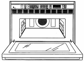
Fgr. 33 The front door of the JEBC200 microwave oven. 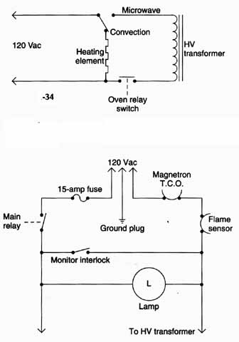
Fgr. 34 The microwave circuits are switched out with the convection oven cooking switch. Microwave, 120 Vac, Convection, Heating element, HV transformer, Oven relay switch; 15-amp fuse; Magnetron; Flame sensor; main relay; Ground plug; Monitor interlock; Lamp. Fgr. 35 Several interlock switches are found throughout the oven. To HV transformer. Flame sensor: The flame sensor is located on the exhaust duct in this GE oven. The tempera ture rating is 248 degrees Fahrenheit. The flame sensor will open if the heat exceeds that limit. Check the flame sensor continuity with the ohmmeter range. The flame sensor is found in series with the ac line voltage ( fgr. 36). Fuse: Most ovens are protected with a 15-amp, chemically active fuse. Replace with the same type of fuse. You might find a fuse resistor circuit in other ovens ( fgr. 37). The fuse resistor assembly senses an increase in current in the transformer secondary circuit and opens up the primary transformer circuit. 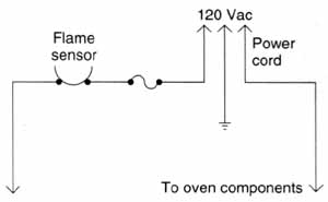 Fgr. 36 The flame sensor is located in series with the ac fuse. 120 Vac. To oven components. Flame sensor. Fluorescent tube: A fluorescent display shows the time and operation numbers, making them visible to the eye. The fluorescent tube is controlled by a microcomputer or control IC (integrated circuit) located on the control board. Gas sensor: The gas sensor is a semiconductor device that detects vapor, aroma, moisture, and humidity coming from the food as it cooks. A gas sensor is now included in some microwave ovens. It automatically adjusts the cooking time for various foods. The gas sensor is controlled by the control board ( fgr. 38). 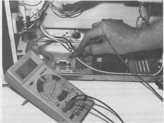 Fgr. 37 Check the 15-amp chemical fuse with an ohmmeter. 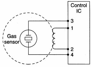 Fgr. 38 Basic oven components. Humidity sensor. The gas sensor detects moisture, Vapors, and humidity from the food in the oven. 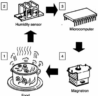 Fgr. 39 The humidity sensor detects steam in the cooking cycle. Microcomputer; Humidity sensor, Food, Magnetron Light switch: The light switch turns the oven light on so the operator can view the contents in the oven cavity. This switch might turn the light on when the door is opened or closed. Usually, no oven light Indicates a blown fuse, a defective switch, or a defective light. You might find more than one oven light in some ovens. Gas: The humidity sensor detects steam during the cooking period. In Panasonic ovens, the sensor is located close to the exhaust vents, where steam generated from the food is exhausted with circulating air ( fgr. 39). The magnetron is a large vacuum tube in which the electrons flow from the heated cathode to a cylindrical anode surrounded by a magnetic field ( fgr. 40). These electrons are attracted to the positive anode, which has a high dc voltage. The magnetron tube oscillator has a very high frequency of 2450 MHz HF energy. The radiated HF energy cooks the food placed in the oven cavity. Monitor or safety switches: The monitor switch is intended to prevent the oven from operating by blowing the fuse in case one of the other interlock switches fails to open when the door of the oven is opened ( fgr. 41). This safety switch normally has open contacts when the door is closed. The entire ac brie is placed across the monitor or safety switch when one of the other interlock switches fails. This blows the 15-amp fuse and pre vents radiation from reaching the operator. 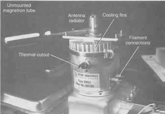 Fgr. 40 The magnetron has several different elements than the vacuum tube. 120 Vac; Monitor switch; To control circuits 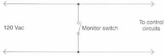 Fgr. 41 The monitor switch blows the fuse when the oven does not shut off after the door is opened. Oven lights: Most oven lights come on when the door is opened or when the oven begins to cook. The oven light might be located in the circuit after the triac device or control relay ( fgr. 42). The oven light is located outside of the oven proper and shines through perforated holes. 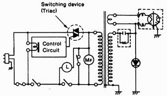 Fgr. 42 The oven light is found after the control relay or triac assembly. -Oven cavity repairs- When the inside of an oven receives heavy gouges or scratch marks, chips, and flakes inside the oven area, touch them up with a white MWO cavity paint spray. A specially formulated microwave oven paint is used to cover these areas. The ivory white aerosol oven touch-up paint is supplied by Panasonic #ANEO887L1OAP. If the paint cannot be found locally, it must be shipped by UPS Ground Service, due to chemical content. Check electronics and microwave oven manufacturer wholesale or parts depots that might stock the touch-up spray paint. Oven sensor: The oven sensor is a negative coefficient thermistor—that is, when the temperature goes up, the resistance goes down. The sensor in a GE JEB100 oven mounts on one side of the oven. Measure the resistance of the sensor around 60,000 ohms in this oven ( fgr. 43). Power relay: When the food is placed in the oven and the door is closed, the primary and secondary interlock (power relay) switches are closed ( fgr. 44). Now when the start pad is touched, the main relay and the power control relay are energized by the touch control circuit. Both relay switches are in series with the HV transformer. If either relay won’t function or has bad switch points, the 120-volt ac voltage is not found at the primary winding of high voltage transformer. Switching device (Triac) POWER CORD The probe jack is located inside the oven and provides an easy method of plugging in the temperature probe. In some ovens, when the cooling probe is out of the jack, make sure to turn the cooking control off, or the oven won’t operate. Always remove the temperature probe when the oven is empty. Don’t let the probe touch any metal sides when in operation. 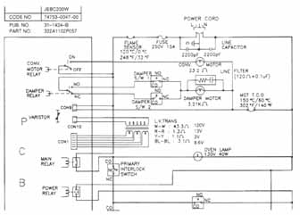 Fgr. 43 The oven sensor is connected to the touch panel circuits in the GE JEB100 oven. 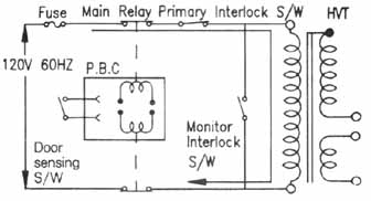 Fgr. 44 The power relay is in series with the bottom leg of primary winding of HV transformer. Probe jack, Rectifier A special silicon diode is a solid-state device that allows current flow in one direction but prevents current flow in the opposite direction. The rectifier and capacitor provide an HV doubler circuit. The diode acts as a rectifier by changing alternating ac current into pulsating dc ( fgr. 45). 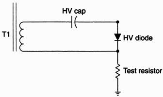 Fgr. 45 The silicon diode rectifies the ac current into a pulsating dc voltage. HV cap; HV diode , Test resistor. Relays: The cook or power relay provides ac voltage to the power transformer circuits. In some ovens, the coil of the cook relay might be energized by the control unit ( fgr. 46). A surge current relay, used in conjunction with a low-value resistor, might be used as a current limiting device. The contacts of the select relay complete the circuit to the fan motor and oven light. 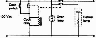 Fgr. 46 The power relay or cook switch provides power or ac voltage to HV transformer. 120 Vac Resistors A resistor is an electronic component that limits the flow of current or provides a voltage drop. The bleeder resistor across the HV capacitor lets voltage bleed off to chassis ground, through the HV diode. A fuse resistor in some ovens acts as a sensing device to an increase of current in the transformer secondary circuit and opens the transformer primary circuit. You might find a surge resistor located in the ac input circuit of some ovens to prevent damage to the oven circuits when power line outage or lightning occurs. A test resistor is used to measure the current of the magnetron tube. Rotary antenna Usually, the rotating antenna is located in a plastic tower in the middle of the cradle. The antenna assembly has several blades that rotate to stir the RF energy over the food in the oven cavity. The rotary antenna might be rotated with a separate motor or with a pulley on the fan blower motor. In the early ovens, the moving antenna was found on top of the oven cavity. Now the antenna assembly might be found under the bottom floor shelf ( fgr. 47). Smart board The smart board in the GE JEB100 oven is the panel controls parts mounted upon a separate PCB. The smart board contains the convection motor relay, damper relay, varistor, transformer connector 1 and 10, main relay, power relay, and heater re lay. All of these components are connected to the various oven circuits ( fgr. 48). Stirrer motor A stirrer motor is located at the top of the oven cavity. The motor rotates or spreads the RF energy for even cooking in the oven ( fgr. 49). Some ovens turn the food instead of using a stirrer motor. The stirrer motor might incorporate a separate ac motor, or the fan might be rotated by a pulley-belt arrangement on the oven fan. Stirrer shield The stirrer shield is located at the top of the oven cavity covering the RF wave- guide opening. This shield prevents food or other particles from going into the wave- guide opening. The shield might need to be replaced when bumped, cracked, or broken by food being placed in the oven. The stirrer shield might be constructed from polypropylene material, which is transparent to microwave energy. Stop switch The stop switch is a closed contact in series with the start switch and power relay. When the stop switch is pressed, the circuit is broken and oven operations are stopped. Temperature fuse The temperature fuse is in series with the ac oven fuse (20 amp). A thermal or temperature fuse can be found in some Canadian models. This fuse can be checked with the ohmmeter ( fgr. 50). Thermal cutout The thermal cutout is designed to prevent damage to the magnetron tube if the magnetron becomes overheated. Under normal operation, the thermal cutout re mains closed ( fgr. 51). In some microwave ovens, an oven thermal cutout device is used in conjunction with the fan motor to cool the oven. The contacts of the oven thermal cutout are open at normal oven temperatures. 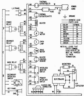 Fgr. 47 Wiring diagram of a Samsung microwave oven. Thermistor: You might find that a thermistor is used with the temperature control unit. The resistance of the thermistor in the temperature probe changes with the food temper- attire determining the time of cooking. The temperature in the oven cavity is detected through the resistance of the thermistor. The thermistor is a negative temperature coefficient component. A temperature probe is not found in all microwave ovens. 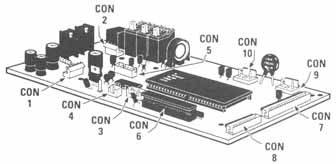 Fgr. 48 The smart board of a GE microwave oven. 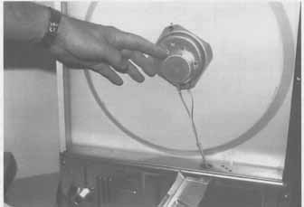 Fgr. 49 The stirrer motor is located at the top and turntable motor at the bottom of oven cavity. Thermostat A thermostat is found in some convection ovens. This thermal device senses the temperature of the convection air passing through the convection air guide. Different degrees of temperature might he selected by rotating the convection control shaft (90-465°F). Normally, the thermostat contacts are closed ( fgr. 52). The thermostat is in series with the convection heating element. 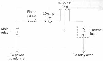 Fgr. 50 The thermal fuse is in series with the 15-amp oven fuse. Flame sensor; 20-amp fuse; Main relay; ac power plug; Thermal fuse; To power; To relay oven transformer. 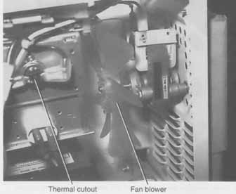
Fgr. 51 The thermal cutout upon magnetron shuts down the oven if magnetron runs too hot. Thermal cutout, Fan blower. Timer: You might find more than one timing device in the microwave oven. One timer might be used for from zero to five minutes of cooking time, while the other timer has a longer cooking operation. The timer switch contacts are mechanically opened or closed by turning the dial knob located on the timer motor shaft ( figure 1 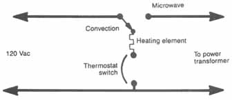
Fgr. 52 The thermostat or convection switch cuts out the ac voltage upon heater element. 120 Vac; Convection, Heating element, Thermostat switch, To power transformer Timer bell: The bell striker is mechanically driven by the timer motor. It rings once at the end of the cooking cycle, indicating that the food is ready. A defective timer assembly can prevent the bell from ringing. Timer motor: The timer motor is energized through the timer contacts. When the timer reaches the 0 point on the scale, the timer switch opens the motor circuit, and the cooking cycle stops. The rotating timer motor determines how long the oven remains in the cooking mode. In some ovens, the fan motor remains in operation until the contact of the oven thermal output opens up. 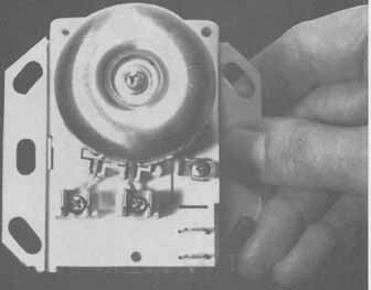
Fgr. 53 The timer assembly turns on and off the oven in the cooking process. Microwave Touch control panel: The touch control panel in the GE JEB200 contains key pads, control panel, LED display, ribbon cable and pin connectors. In other ovens, the touch panel may include the number display, varistor, main relay, secondary interlock relay, speaker, small power transformer, function key switches, touch control components, and flat ribbon cable ( fgr. 54). In most cases, the control panel is either exchanged or sent in for repair. 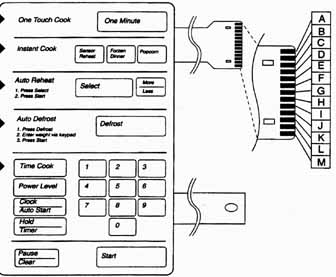
Fgr. 54 The touch panel control in a Samsung MG 5920T. One Touch Cook; Auto Defrost Transformer: The HV power transformer is a step-up voltage device operating from the 120 (Vac) power line ( fgr. 55). The stepped-up voltage of the secondary winding is approximately 2500 Vac and provides voltage to the voltage doubling circuit. A separate step-down secondary winding of the power transformer provides filament voltage to the magnetron tube. Triac: 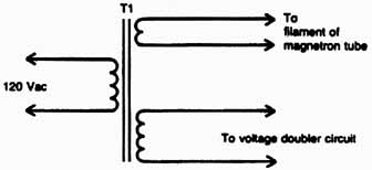
Fgr. 55 The HV transformer provides a filament or heater voltage and HV voltage for the voltage doubler circuits. To voltage double circuit. You might find a triac module in some microwave ovens m place of a power relay. Usually the triac module is controlled by the electronic controller circuit ( fgr. 56). A defective triac might prevent the oven from going into the cooking cycle. 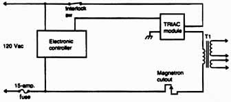
Fgr. 56 A defective tube might let the oven run after it has been shut off. Turntable motor: In some ovens, a turntable device is used to rotate the food for even cooking. The turntable is rotated by a separate turntable motor assembly located at the bottom of the oven. A glass tray holds the food and rotates on several small rollers ( fgr. 57). Vari-motor The vari-motor assembly consists of a van-motor, van-switch, CAM roller, gears, and mounting bracket. The motor rotates the van-CAM and activates the van-switch on and off intermittently, supplying power to the power transformer. The repetition rate can be changed by turning the mode selector. Vari-switch The vari-switch is part of the van-motor assembly and operated by the CAM roller. If the variable cooking mode selector is set at warm, defrost, summer, or roast position, ac power is supplied to the power transformer intermittently within a 30-second time base. Only a few microwave ovens contain a van-motor and van-switch assembly. Varistor You might find a varistor located in the ac input power circuit to protect the oven components from excessive power surges or lightning damage. The varistor will pre vent the excessive voltage from entering these circuits. The varistor arcs over and opens the power fuse, preventing damage to the oven circuits. This same type of varistor components is found in the power line circuits of the latest TV receivers. Waveguide: The magnetron tube is connected to the waveguide assembly. RE energy from the magnetron tube’s antenna radiates power into the waveguide and oven ( fgr. 58). The waveguide channels the RE power from the magnetron into the oven. A wave- guide cover, mounted at the top of the oven cavity, prevents food particles from entering the waveguide assembly from the oven area. Like the TV receiver or any electronic device, various components can break down and cause many different symptoms within the microwave oven. With proper test equipment and tools, each defective component can be quickly replaced or repaired. Although most appliances and TV service centers have the basic tools for microwave oven repair, a few special added pieces of test equipment make the task a lot easier and are really a must when servicing microwave ovens. 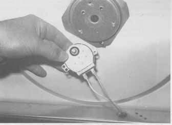 Fgr. 57 The turntable motor is at the bottom of the oven cavity. The block diagram: The ac input circuit consists of interlocks, fuse, oven lamp, drive motor, fan mo tor, main and power relays. Many components found on the touch panel control parts are in the low voltage or ac input circuits. The control panel can control relays and triac assemblies in the primary winding of high voltage transformer. The FW transformer supplies high voltage to the magnetron tube, which is built up with a voltage doubled capacitor and HV diode. The heater terminals are at high voltage potential while the anode of magnetron is grounded ( fgr. 59). 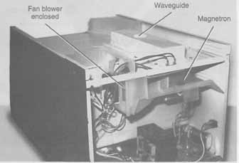
Fgr. 58 The waveguide assembly guides the RF energy to the oven cavity from magnetron. Magnetron; Fan blower enclosed; Waveguide 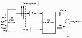
Fgr. 59 The block diagram of most microwave ovens with a control panel. Home Guide/index top of page |