The Service Entrance
Home|
In order to limit shock and fire hazard from poorly made or deteriorated connections and splices in wires, and to protect the wiring from physical damage, the National Electrical Code (NEC requires that every switch, every outlet, and every joint in wire or cable must be enclosed in a box, and every fixture must be mounted on a box (with the exception of some fluorescent fixtures described elsewhere in this guide). Keep in mind that all explanations in Sections 9 through 15, except Section 13, are for “new work” the wiring of a building while it is being built. The basic principles for “old work—the wiring of a building after it is built—are covered in Section 13. Study new work thoroughly in order to better understand old work. PLANNING YOUR BOX INSTALLATION Many boxes are made of metal with a galvanized finish. Boxes made of insulating materials such as PVC, fiberglass, and other nonmetallic material are also common. Such boxes are used mainly with nonmetallic-sheathed cable and nonmetallic race- ways. Metal boxes and their accessories are covered first because they are easier to visualize as we cover certain terminology common to all boxes.
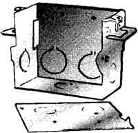
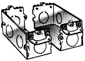
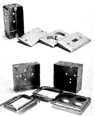
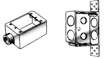
Types of boxes : Boxes are called switch boxes or outlet boxes depending on their shape and purpose. Wires and cables must he brought into the boxes through openings of the appropriate size, and “knock outs” are provided for this purpose. These are sections of partially punched out metal that are easily removed to form openings by loosening the knockout with a sharp blow on a screwdriver placed against it and then removing with pliers. Switch boxes: The most common type of switch box is shown in Fig. 9-1. The mounting brackets on the ends of each box can be adjusted to bring the front of the box flush with the surface of the wall. Two “ears” with tapped holes for screws hold the switches, receptacles, and similar devices installed in the boxes. Switch boxes are sometimes used for fixtures of the wall- bracket type weighing up to 6 pounds with a box located at each point where a bracket is to be installed. The NEC requires boxes to have a depth of at least -inch where a device such as a switch or receptacle is to he installed. Most are at least 15/16-inches deep, but the deeper ones (2 to 3½ inches deep) are handier and more generally used. Each box holds one device. When two devices are to be mounted side by side, two boxes can he changed into a single “two gang” box by simply throwing away one side of each box and bolting the boxes together as in Fig. 9-2. Use the screws that are part of the boxes.
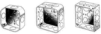
Outlet boxes: Figure 9-3 shows the most common outlet box. It is octagonal in shape and available in three sizes: 3¼-inch, 3½-inch, and 4-inch. The 4-inch size is the most common today, permits more wires to be used, avoids cramping, and in general reduces the time required for installation. If space permits, use a box at least 1½ or even 2 1/8 inches deep.
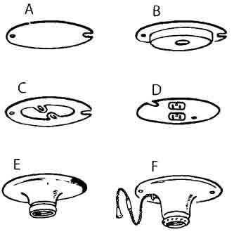
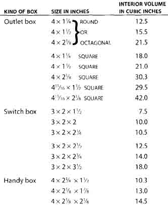
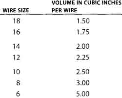
Outlet boxes must always be covered. A great many different covers are available. Some common ones are shown in Fig. 9-4. The cover at A is a blank cover for a box that is used only to hold a splice or tap. The one at B is a drop cord cover—the opening for the drop cord is fitted with a smooth bushing to eliminate sharp edges. At C is a spider cover used to mount surface-type switches. At D is a cover with a duplex receptacle. At E is a keyless receptacle for a lamp. Another lamp receptacle is shown at E, this one with a pull chain. Handy boxes : If an ordinary switch box is mounted on the surface of a wall, as in a basement or garage, the sharp corners of the box and cover are a nuisance. In such locations use a box with rounded corners, known as a “handy box” or “utility box’ and shown in Fig. 9-5. Square boxes : Boxes 4 inches square are large enough to hold two devices. Figure 9-6 shows a square box and the special covers used with it. These boxes are used for surface mounting as well as for general-purpose wiring and are especially handy when many wires must enter the same box. To find the minimum size box that is permitted, add up the required volumes listed in the box below. Choose all volumes from Table 9-2. Then match the total calculated volume in cubic inches to a box size in Table 9-1. To calculate minimum box size, add up these required volumes, choosing volumes for wires from Table 9-2 below and then matching total calculated volume to a box size in Table 9-1. 1 VOLUME for each wire originating outside the box and terminating or spliced within the box. 1 VOLUME for each wire passing through the box without splice or termination (as may happen in conduit wiring). 1 VOLUME for each fixture wire. Exception: four or fewer fixture wires and one equipment grounding wire entering the box from a domed fixture canopy are not counted. 1 VOLUME for any number of internal cable clamps (Fig. 9-14), basing the volume on the largest wire in the box. Do not add for external cable connectors (Fig. 9-11). 1 VOLUME for any number of fixture studs (Fig. 9-15 top), basing the volume on the largest wire. 1 VOLUME for any number of hickeys (Fig. 9-15 bottom), basing the volume on the largest wire. 2 VOLUMES for each yoke or strap containing switches, receptacles, pilot lights, etc., basing the volume on largest size wire connected to a device on that yoke, and then doubling it for two volumes. 1 VOLUME for any number of equipment grounding conductors, basing the volume on the largest equipment grounding conductor in the box.
Example of box size calculation consider a feed-through receptacle location with two 12-2 with ground cables entering the box through internal cable clamps. From Table 9-2, each 12 AWC wire requires 2.25 cubic inches. The grounding conductors are also 12 AWG , so the calculations are:
Thus from table 9-1, the smallest square outlet box permitted is a 4 x 1¼ -inch box, and the smallest switch box permitted for this application is a 3 x 2 x 3½-inch box. Both arc 18 cubic inches.
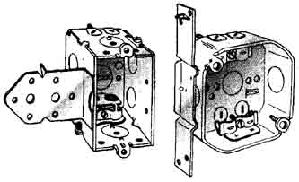
INSTALLING BOXES NEC 210.70 requires the following areas to be equipped with at least sonic lighting controlled by a switch: every livable room; bathrooms, hallways, stairways, attached garages; detached garages if wired; and the following spaces if used for storage or containing equipment requiring servicing—attics, underfloor spaces, utilities rooms, basements. In addition, each entrance into the house must have an outdoor light controlled by a switch inside the house. All required lighting must consist of permanently installed lighting fixtures in bathrooms and kitchens, hut in other habitable rooms it may be provided by floor or table lamps plugged into receptacles controlled by a wall switch. Boxes for switches should he located near doors so the switches are easily accessible as the door is opened. Consider which way the door is to swing and install the box on the side opposite the hinges, with the center of the box 48 to 52 inches above the floor. For receptacles, the usual height is 12 to 18 inches above the floor. Each room should have at least one receptacle located conveniently for a vacuum cleaner and other portable items. Mounting switch boxes : Boxes must he firmly secured to studs. Some boxes conic with nails attached. If mounting nails pass through the box, they must not lie more than inch from the back or ends. It is usually faster to use boxes with mounting brackets (Fig. 9-7). Always install boxes so their front edges are flush with the surface of the finished wall. If the box is not adjacent to a stud, use an octagonal or square box with a plaster ring and a hanger (see next paragraph).
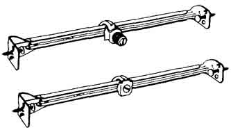
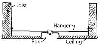
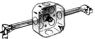
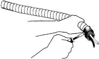
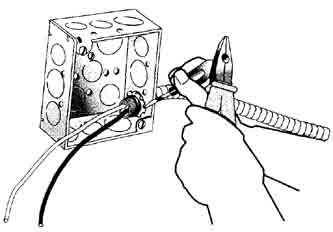
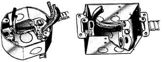
Mounting outlet boxes : If the box is to lie installed near a stud, use an outlet box with a mounting bracket such as shown in Fig. 9-7. If the box must he mounted between studs or joists, use a hanger of the type shown in Fig. 9-8. It is adjustable in length and has a fixture stud sliding on it. Remove the center knockout in the box, slide the stud to the position wanted, push the stud through the knockout, and drive the locknut on the inside of the box securely home. Then nail the hanger to the studs or joists so the front edge of the box (or the cover mounted on it if it is the type shown in Fig. 9-6) will be flush with the wall or ceiling as shown in Fig. 9-9. Even handier are pre-assembled boxes with hangers as shown in Fig. 9-10. Wiring at boxes Regardless of the wiring method you use, let 6 to 10 inches of wire extend from the f of each box. The length depends on your choice of two methods of connecting the wire to the terminal screw as discussed and shown earlier. The NEC minimum is in two parts. The wires (including equipment grounding wires, as with Type NM cable) must be at least 6 inches long measured from where the individual wires emerge from the raceway connector or cable sheath, and they must be long enough to extend at least 3 inches outside the box. The only exception (other than for very large boxes) is for wires that have no splices or connections, hut merely pass through the box, usually from raceway to raceway These wires have no minimum length. Anchoring connectors : When cable of any style is used for wiring, the NEC requires that it he securely anchored to each box that it enters. There are many kinds of connectors for this purpose; an assortment is shown in Fig. 9-11. The connector at A is used for ordinary purposes, the one at B for a sharp 90-degree turn, and the one at C when two pieces of cable must cuter the same knockout. To anchor the cable, first remove the locknut from the connector. Attach the connector to the cable with the clamp screw as in Fig. 9-12, then slip the connector through the knockout, and install the locknut inside the box as shown in Fig. 9-13. Be sure to drive the locknut down solidly so the tugs on it actually bite into the metal of the box to form a good continuous ground. Some newer connector designs snap into and hold tight to standard knockout openings, requiring no locknut. Some boxes have built in clamps that securely hold the cable entering the box, making separate connectors unnecessary. Typical boxes of this kind are shown in Fig. 9-14.
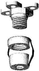
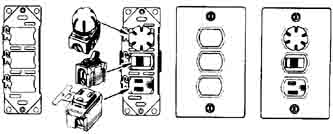
Fixture studs : Small, lightweight fixtures are often mounted directly on outlet boxes, anchored by screws entering the “ears” of the box as explained at the beginning of this section under the heading “Switch boxes” Other fixtures commonly mount to fixture bars that are secured to the box ears. Heavier fixtures need additional support. Install a fixture stud (see Fig. 9-15) in the back of the box using stove bolts. This is unnecessary if a hanger (Fig. 9-8) is used to support a box mounted between studs or joists. With a fixture stud, a hickey may be needed between the stud and fixture. Fixtures above 50 pounds (or heavier if the box is so listed) must he supported directly by the building structure. Boxes for suspended ceiling (paddle) fans : Boxes for the support of ceiling fans must be listed for the purpose. Fans weighing more than 35 pounds must be supported independently of the box, unless the box has been listed for additional weight. Consider using a box listed for fan support at every ceiling outlet location where a paddle fan might be installed at a later date, because installing a fan support box at an existing outlet can be difficult. Boxes for recessed fixtures : If the bottom of your fixture will he flush with the ceiling it is called a “recessed fixture:’ If your recessed fixture includes a junction box marked for 60°C branch circuit wiring, ordinary branch circuit wiring can he connected directly to it, and most recessed fixtures available today have such boxes. Be sure to observe any fill or other restrictions on the number and type of wires allowed in such boxes, because they will not be of any standard size. Boxes for interchangeable devices : Up to three interchangeable devices can be installed in an ordinary single-gang box. Figure 9-16 shows a faceplate with three openings, and an assortment of devices such as switches, receptacles, and pilot lights. Plates are also available with one or two openings. The plate is supplied with a metal strap with three openings on which you can mount any combination of one, two, or three of these specially sited de ices. The three devices can then be installed in a single-gang box. Three standard devices would require a three-gang box which costs more, takes more space and requires much more installation time. Caution: Remember that the number of wires entering any box is limited; review above section on calculating minimum site boxes. When a switch box is not large enough for the wires necessary to connect to three devices on one strap, use a 4-inch-square box and a single-gang plaster ring as shown in Fig. 9-6. Nonmetallic outlet boxes : Nonmetallic boxes, for reasons of cost, have largely supplanted metal boxes in today’s market, particularly for residential occupancies. In addition to cost, nonmetallic boxes are largely immune to corrosion, and for surface applications using boxes of PVC, fiberglass, or other nonmetallic material provides insurance against shock. When metal boxes are used in barns and similar locations, they tend to rust out just like conduit. Also, when used with nonmetallic-sheathed cable, a metal box that is poorly grounded becomes “hot” when a hot wire becomes accidentally grounded inside it. Any person or animal touching the box will receive a shock that can he dangerous to humans and even more so to animals. Nonmetallic boxes (and covers) are shown in Fig. 9-17. Use them as you would metal boxes; however, the NEC does not require that cable be anchored with connectors to single-gang nonmetallic switch boxes if the cable is supported within 8 inches of the box measured along the cable sheath, and the sheath extends into the box at least 1/4 inch. At other than single-gang nonmetallic boxes, the cable must be secured to the box, as it must be to all metal boxes. (Anchoring with connectors is discussed above.)
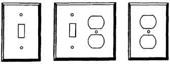
Other nonmetallic boxes are shown in Fig. 9-18. Boxes with hubs, like the one at left, are for surface wiring, and with the proper covers they are weatherproof Boxes with knockouts can be used either concealed or exposed. Note that nonmetallic boxes differ from metallic boxes in that they do not come in standardized sizes. This means that in order to decide on allowable wire fill, you have to do the calculations covered earlier in this section, based on the actual volume of each box, which will be marked on the inside of the box. Nonmetallic faceplates or covers are recommended when using nonmetallic boxes, particularly in corrosive locations. If metal faceplates are used, they must be grounded, which is more or less automatic with receptacles, because the mounting strap is usually connected to the green grounding terminal. Toggle switches require a special switch having a grounding terminal on the mounting strap to which the grounding wire in the nonmetallic-sheathed cable must be connected. SELECTING SWITCHES While all common switches have the general appearance of the common wall light switch, there are three varieties that you should understand: Single-pole is used to turn a light on or off from one point. It has two terminals and the words ON and OFF on the handle. Three-way is used to turn a light on or off from two separate locations. It has three terminals and a plain, unlabeled handle. For the wiring of three-way switches see this page. Four-way is used in combination with three-way when a light must be turned on or off from more than two locations. Use three-way switches at two of the points, and four-way at the remaining points. The four-way has four terminals and a plain, unlabeled handle. For the wiring of four-way switches see this page. Switch ratings : Switches are designed for use at an amperage and voltage not higher than the limits stamped into their metal mounting yokes. Some switches are rated “10A 125V - 5A 250V” indicating that the switch may be used to control loads not over 10 amps if the voltage is not over 125 volts, but only 5 amps if the voltage is higher but not over 250 volts. Most are rated 15A 120V, or 15A 120/277V. Other switches are available for higher amperages. Grounding for switches : The yokes of all toggle switches, including dimmers as described below, are required to be grounded so that a metal faceplate, whether installed or not, will be grounded. The switch yoke can be grounded to the grounded metal box, or an equipment grounding conductor must be connected to a green terminal screw on the yoke. Types of switches In addition to the common general-use switches, there are switches with a variety of special features that enhance comfort, convenience, and safety. Some of these are described here. AC general-use snap switches: The most commonly used switch today is called the “ac general-use snap” type in the NEC. It is very quiet in operation and lasts a long time. It is identified by the letters “AC” following the ampere and voltage rating on the yoke. As the name implies, it must not be used on dc circuits. On ac, it may be used for any purpose with two exceptions: a) it must not he used to control tungsten-filament lamps (ordinary lamps) at voltages above 120 volts; b) if used to control a motor, it may be used only up to 80 percent of its ampere rating. AC-DC general-use snap switches : Older style switches are called “ac dc general use” in the NEC. If the switch does not have “AC’ at the end of its rating, it is an ac-dc type. This style may he used on dc-only circuits as well as on ac circuits. If your wiring was installed many years ago, the switches are likely to be the ac-dc type. If one of them fails, you may replace it with the more readily available ac-only type. Lighted switches: Switches are available with a tiny neon light in their handles to make it easy to locate the switch in the dark. The light has an exceedingly long life, possibly 20 years, and consumes so little power that it costs perhaps one cent per year to operate. Quiet switches: Ordinary switches can make an audible click when turned on and off. The “ac general use” switch is very quiet. Also available is a completely silent switch that uses a bit of mercury in a glass tube to make and break contact. Mercury switches will not operate unless installed in a vertical position. Dimmer switches: Where it might be desirable to control the level of brightness, such as in dining rooms or family rooms, ordinary switches can be removed and replaced with special dimming switches. Some dimmers are designed to be used only with incandescent lamps and others are for use only with fluorescent lighting. One inexpensive type of dimmer switch provides HIGH—OFF—LOW positions and controls up to 300 watts. It can be used to replace only an ordinary single-pole switch, not a three-way. The somewhat more expensive type controls brightness continuously from off to full brightness. Some models are available in the three- way type, replacing one of a pair of three-way switches. FACE PLATES Receptacles and switches when installed are covered with faceplates (also called wall plates) of the type shown in Fig. 9-19.These are available in molded plastic and nylon in an assortment of colors and in other materials such as steel, brass, or ceramic. Use the kind you like best. Metal faceplates must be grounded.
PREV: The Service Entrance Home • • |
Wednesday, 2009-04-15 20:06 PST
