The Service Entrance
Home|
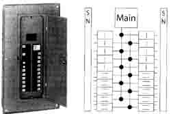
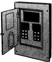
ELECTRIC POWER FLOWS from the supplier’s transformer through a set of three wires to your service entrance where the wires enter the building. This section discusses the design and installation of a service entrance for a house. Installations for farm buildings are discussed in a later section. PLANNING YOUR SERVICE ENTRANCE These are the components of the service entrance. Outside the building— • Service head, also called the entrance cap or weather head • Insulators anchored to the building below the service head—this is where the power supplier’s wires end -- Service entrance cable or wires in conduit leading from the insulators to the • service head and down to the meter socket • Meter socket • Service entrance cable or wires extend from the meter socket into the building Inside the building— • Service entrance cabinet that contains the disconnecting means and overcurrent protection—either circuit breakers or fuses in a panel-board • Ground connection—a ground wire from the incoming service to the busbar in the cabinet and back outside the building to the grounding electrode system 120-volt or 120/240-volt current. The number of wires installed by your power supplier in your service entrance determines the type of current you will have. Two-wire service entrance : When only two wires are installed, only 120-volt current is available. One of the wires is white (sometimes bare) beginning at the insulators, and is grounded. It is not a neutral wire; there cannot be a neutral in a two-wire circuit. The hot wire is black. Three-wire service entrance : The standard installation today is the three-wire entrance. When three wires are installed, both 120 volts and 240 volts are available as shown in FIG. 7-1. The voltage between N and A, or between N and B, is 120 volts; between A and B it is 240 volts. The wire N is white (sometimes bare) beginning at the insulators. It is grounded, and up to the service equipment inside the building it is a neutral wire. The two hot wires can be any color except white or green, but are usually black and red, or both black. Service equipment rating: Service circuit breakers are rated at any of the standard sizes for circuit breakers, but the enclosure must be rated as suitable for use as service equipment. Service fusible switches are rated at 30, 60, 100, and 200 amps, although any standard-size fuse may be used within such a switch, provided the switch is rated as suitable for use as service equipment. Equipment larger than 200 amps is available for larger installations. Some power suppliers will furnish a self-contained meter that will handle a 400-amp service, but beyond that the meter must be served by current transformers in a separate enclosure ahead of the service disconnect. The service equipment of a single-family dwelling is required to have a rating of 100 amps or higher. In wiring buildings other than houses, a 30-amp service may be installed if there are not more than two 2-wire circuits. In all other cases, the equipment must be adequate for the load involved, but never less than 60 amps. See 230.79 in the National Electrical Code (NEC). Note that feeders to individual dwelling units in an apartment house have essentially no arbitrary minimum size; they are simply sized to meet the load (but no less than 30 amps by NEC 215.2(A)(2)(2). To determine the maximum wattage, or volt-amperes (VA), available with any size switch or breaker, multiply the amperage rating by the voltage (240). For example, a 60-amp switch or breaker will make available 14,400 VA (60 x 240 = 14,400), and a 100-amp size will make available 24,000 VA (100 x 240 = 24,000). What size service? To determine the size of service you need, begin by computing the total probable load in volt-amperes (net computed VA). A 100-amp service is the smallest permitted by the NEC. The 100-amp service provides a maximum capacity of 24,000 VA. If the total of the “net computed VA” that you just calculated comes to more than 24,000 VA, does it follow that a service larger than 100 amps is necessarily required? No, because all the lights and appliances listed in the tabulation will not be in use at the same time. But remember that the assortment of appliances you include in your first tabulation represents your present ideas. As time goes on, you will add more appliances. A 150-amp or 200-amp service will meet future needs more adequately. In some areas, local codes are already requiring services larger than 100 amps. The larger services cost relatively little more than the 100-amp size. Service entrance wire size : Since 100-amp service is the minimum for homes, select a wire with ampacity of 100 or more amperes. For installations other than homes, NEC 230.42 requires that the conductors be sized to carry the load as calculated in Article 220. Examples of dwelling service calculations are found in NEC Annex D, Examples D1a, D1b, D2a, D2b, and D2c. CALCULATING TOTAL PROBABLE LOAD IN VOLT-AMPERES Area of house* _______ square feet x 3 VA _______ VA Two appliance circuits ... 3,000 VA One laundry circuit ... 1,500 VA Range, if used ________ watts Water heater, if used ________ VA Other permanently connected appliances ________ VA Total _______ VA Each of these circuits will provide 2,400 VA (20 x 120 = 2,400), but for the purpose of this calculation use 1,500 VA per circuit (3,000 VA altogether) because it is not likely that both circuits will be loaded to capacity at the same time. If more such circuits will be provided in any particular installation, multiply the number of such circuits by 1,500 VA. Per the NEC, allow 8,000 watts if the rating of your range (or countertop unit plus separate oven) is 12,000 watts or less. If rated over 12,000 watts, add 400 watts for each additional kilowatt or fraction of a kilowatt. For ranges, watts and VA are considered equivalent. For examples and further details, see Annex Din the 2009 NEC. DISCONNECTING MEANS At the service location you must provide equipment, called a panelboard or load center, that allows you to disconnect all the wiring from the power source. You must also provide either circuit breakers or fuses to protect the installation as a whole as well as each branch circuit individually. The service disconnect may be either inside or outside. In conjunction with the discussion that follows, be sure to read “Circuit Protection and Planning?” Advantages of circuit breakers : Most installations today use circuit breakers because of their many advantages over fuses. If a breaker trips, you can restore service by merely flipping its handle (after correcting the problem that created the overload that tripped the breaker). You can also disconnect an individual circuit by using the breaker as you would a switch. The breakers will carry non-dangerous temporary overloads that would blow ordinary fuses. Selecting breaker equipment : Most service entrance equipment as purchased will contain one large (100-amp or larger) two-pole main breaker that will protect the entire installation and will let you disconnect the entire installation from the power source by merely turning this one breaker to the OFF position. But there must be more breakers to protect individual circuits. You will need a single-pole breaker for each 120-volt circuit and a two-pole breaker for each 240-volt circuit. These branch-circuit breakers are not part of the equipment as purchased, but the cabinet contains an arrangement of busbars into which you can plug as many individual single-pole and two-pole breakers as there is room for. A two- pole breaker occupies the same space as two single-pole breakers. Each panelboard accommodates only as many breakers as its UL listing permits. Typically, a 100- amp panelboard will accommodate 20 plug-in breakers; 125-amp—24 breakers; 150 amp 30 breakers; and 200 amp—40 breakers. The overall rating of the panelboard must equal or exceed the load served as calculated by NEC Article 220. Figure 8-1 shows a circuit breaker cabinet with its internal wiring diagram. The diagram shows space for 20 circuits. Select equipment that provides for the number of branch circuits you need plus a few additional spaces for future expansion. For help in calculating your circuit needs see the “What size service?” discussion earlier in this section and Table 5 3.
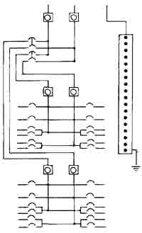
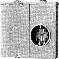
Split-bus breaker equipment: Somewhat less popular (and in a few localities prohibited by local ordinance) are “split bus” service entrance panelboards. The NEC permits two main disconnects in one service panelboard. To disconnect everything from the power source, it is necessary to turn both of them to the off position. In addition to the main breakers, the cabinet may contain as many breakers as you wish (up to the capacity of the panelboard), single-pole or two-pole, each protecting its own circuit, but all of these smaller breakers must be protected by one of the main breakers. See wiring diagram of Fig. 8-2. An alternate arrangement would be for one of the main breakers to protect all the branch circuits in the service panelboard, and the other main breaker to supply a feeder to a panelboard located elsewhere. Outdoor cabinet In a few areas, it is common practice to use an outdoor cabinet containing the meter socket and the service disconnects. Figure 8—3 shows a meter socket and single main disconnect in one cabinet. In mild climates, all the branch circuits could also originate in this enclosure.
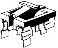
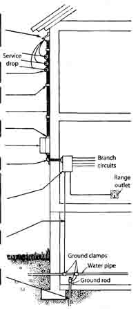
Selecting fused equipment: The type widely used in residential work has two main fuses mounted on a pullout block (Fig. 8-4). With the pullout in your hand, insert the fuses into their clips. One side of each fuse clip has long prongs; the entire pullout has four such prongs. The equipment in the cabinet has four narrow open slots, but no exposed live parts; the live parts are behind the insulation. Plug the pullout with its fuses into these slots; the four prongs on the pullout make contact with the live parts, completing the circuit. Plugging the pullout into its holder is the same as closing a switch with hinged blades; removing it is the same as opening a switch. You can insert the pullout upside-down to leave the power turned off. Such fused service equipment usually contains one main pullout with large fuses protecting the entire load, plus additional pullouts to protect 240-volt circuits with large loads such as range, clothes dryer, and water heater. There are also as many fuse-holders for plug fuses as are needed to protect individual branch circuits: one for each 120-volt circuit, two for each 240-volt circuit. A service panelboard of this type is shown in Fig. 8-5. The wiring diagram is the same as in Fig. 8-1 except that fuses are used in place of breakers. The installation should provide for the number of circuits needed for present uses, plus a few additional spaces for future expansion. These panelboards are common in older installations, but almost impossible to find today at supply houses, having been replaced by circuit breakers for new installations. Fuseholders: For fuses of the cartridge type, the “60 amp” holder accepts fuses rated from 35 amps to 60 amps. The “100 amp” holder accepts fuses rated from 70 amps to 100 amps. The “200 amp” holder accepts fuses rated from 110 amps to 200 amps. Holders for plug fuses accept fuses up to 30 amps (the top rating for plug fuses). In new work, Type S adapters must be used; these allow installation of only the proper fuse to match the ampacity of the wires. Fusible equipment for individual loads is still available and commonly used, particularly for commercial and industrial applications. Fuses can be designed with certain electrical characteristics, including speed of operation and low-current size ranges, that are unavailable in circuit breakers. Split-bus fused equipment: As in the case of breaker equipment, the fused equipment may contain two main pullouts, connected internally so the service wires run directly to each. To disconnect the load completely you must pull out both the main pullouts. The branch-circuit fuses must be protected by one of the main fused pullouts. The wiring diagram of connections within the equipment is that of Fig. 8-2 except that fuses replace the breakers. Old-style fused service equipment : In very old houses you will find service equipment that consists of a main switch with two hinged blades and an external handle used to turn the entire load in the building on and off. The switch cabinet also contains two main fuses. Usually it also contains as many smaller fuses as needed to protect all the individual branch circuits in the house. Sometimes these fuses are in a separate cabinet. If your service is underground, we will cover that here. INSTALLING THE SERVICE ENTRANCE So far we have looked at the major parts that make up the service entrance, and how to select the right kind and size of equipment. The rest of this section concerns the installation of these parts. Figure 8-6 shows the details of a typical service entrance. You will have to install insulators on the outside of the building. The power supplier will run its wires up to that point and connect them there to the service-entrance wires that you provide. You can use special cable for that purpose or run wires through conduit. Your wires will go up to the service head, down to the meter socket, and then into the house to the service equipment. After installing the service equipment, you must properly ground the installation. Then you will be ready to wire the branch circuits. Service equipment location The NEC requires this equipment to be located as close as practical to the point where the wires enter the house. In other words, the service wires must not run 10 or 20 feet inside the house before reaching this equipment. Decide where to put your equipment cabinet before deciding where the wires are to enter the house.
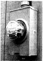
The service head should be mounted higher than the insulators. Let 24 to 36 inches of the service-entrance wire extend out of the head. Your power supplier will connect the service-drop wires to the service-entrance wires. Service insulators must be solidly mounted. Install as high as practical, but lower than service head. Anchor cable to wall with straps. If you use conduit use ordinary pipe straps. Conduit or cable. If you use cable, make a weather- tight connection where it enters the meter socket, using outdoor type of connector. Weatherproof meter and socket. If you use cable, provide a sill plate where cable enters building. Service equipment, which may be any of the types described in this section. Be sure to install enough branch circuits, including spares for future use. If the service equipment is located in the basement, the cable or conduit entry into the building will move down to a point opposite the equipment. Ground wire. Rod may be inside or outside the wall, but should reach permanently moist earth. The heaviest loads in a house—the loads that consume the largest amperages located in the kitchen and basement or other laundry area. Therefore, locate the service equipment so that the circuits using large wires (to range, clothes dryer, and similar equipment) will he as short as possible. In houses with basements, a point more or less under the kitchen is desirable if the service wires can be brought into that location directly from outside. Some prefer to locate the equipment in the kitchen where it is convenient for replacing fuses or resetting breakers. Service equipment must be readily accessible, and it must be in a space that is clear of any obstructions not a part of the electrical installation, both down to the floor and up as far as the structural ceiling. Special NEC rules and allowances apply if the ceiling is more than 6 feet above the service (or similar) equipment, however the)’ are beyond the scope of this book [ NEC 110 to.26(F) if this applies to our situation]. In addition, there must be clear workspace around the equipment, at least 30 inches wide, 3 feet deep, and 6 1/2 - feet high, or higher if the equipment extends higher. Note that switch and circuit breaker operating handles, in general, cannot be higher than about 6 1/2 feet above the floor, allowing most individuals to operate them promptly in an emergency Meter and socket location : The outdoor type of meter is standard today. The weatherproof meter provided by the power supplier is plugged into a weatherproof socket (see Fig. 8-7). The socket is usually, but not always, provided by the power supplier but installed by the contractor, usually about 5 feet above the ground. In the ease of indoor equipment, the meter socket is installed on a substantial board near the service equipment. For a two-family dwelling, two meter sockets are installed in one sheet-steel enclosure. Below the meters each occupancy will have its own service disconnect.
Insulators The incoming service wires are anchored on service insulators installed on the building. They should he installed a foot or so below the highest practical point so the wires to the inside of the house, where they emerge from the service head on the conduit or cable, will slope downward toward the insulators to prevent water from following the service wires into the service head. Shown in Fig. 8-8 are the type of racks used in most localities, usually with 8-inch spacing between insulators (6 inch spacing is allowed in some localities). Individual screw-point insulators (Fig. 8-9) are often used instead of multiple racks. Service wire clearance NEC 2311.24(B) requires that cabled service wires not over 150 volts to ground (or drip loops as illustrated in Fig. 8-19) he kept 1(1 feet above finished grade at the point of attachment to the building; 12 feet above residential property and driveways and commercial property not subject to truck traffic; 18 feet over parking areas and driveways other than residential, and farm properties that are subject to truck traffic. No wires may come closer than 3 feet to an openable window there is no restriction to wires above the top of window), or 3 feet horizontally and 10 feet vertically from any door, porch, fire escape or similar location from which the wires might be touched. If they pass over all or part of a roof that has a rise of 4 inches or more per foot, they must he kept at least 36 inches from the nearest point. If the roof is flatter (less than 4 inches of rise per foot), they must he kept at least 8 feet from the nearest part of the roof.
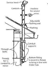
Masts In wiring a rambler or ranch-style house it is difficult to maintain required clearances if the insulators are mounted directly on the side of the house, so a mast is used. Several types are on the market, and Fig. 8-10 shows a typical construction. The service conduit extends upward through the roof overhang and becomes the support for insulators of the type shown in Fig. 8-11. Unless your power supplier has other requirements, the service conduit should not he smaller than 2-inch rigid metal conduit. Smaller conduit could be used if braced or guyed for extra strain support, or either smaller conduit or service entrance cable could be attached to a 4 x 4-inch timber. If the roof overhang does not exceed 48 inches, the service wires may be as low as 18 inches above the overhang. Service-entrance wires Service-entrance wires begin at the insulators where the power supplier’s wires end, and they’ stop at the service equipment where the individual circuit wiring begins. You may use service wire cable manufactured for the purpose, or separate wires in conduit. Service-entrance cable Typically, service entrance cable (Fig. 8-12) is used to bring wires into the building. One of the wires is not insulated and consists of a number of fine wires wrapped around the insulated wires. In use, the small bare wires are twisted together to make one larger wire (Fig. 8-13). The bare wire may he used only for the grounded neutral. Over all is a fabric braid or outer protective layer. This usually has a gray finish which may be painted to match the building. Use cable with at least 2 AWU aluminum wires (or 4 AWG copper, but that is much less common) with a 10 ft-amp main breaker or switch in the case of a single dwelling. Use cable with 4/0 AWG aluminum (or 2/0 AWG copper) wires for a 200-amp breaker or switch at a similar building. In the case of commercial or multi-family dwelling applications, you ill need to go up one wire size on all 100—amp applications, and on any 200—amp application where the calculated load is higher than 180 amps. Services above 200 amps arc beyond the scope of this book. In houses where 30 amp service and 60-amp service are not permitted but may be used in other buildings such as a free—standing studio or workshop on residential property. Use 8 AWU wire with a 30-amp breaker or switch, or 6 AWG with a 60—amp breaker or switch.
If the installation serviced by the service equipment has no significant loads operating at 240 volts, all wires in the cable, including the neutral, must be the same size. But if the installation has an electric range or water heater or other 240-volt loads consuming about one third of the total watts, then you may use cable with the neutral one size smaller than the insulated wires—for example, 2 AWG insulated wires with a 4 AWG bare neutral. Technically, the required calculation for the neutral must be customized to the actual load profile and certain grounding return path issues, but the rule of thumb presented here should be adequate for users of this book.
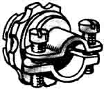
Wherever the cable enters a service equipment cabinet or a meter socket, it must be securely anchored with a connector. Outdoors, a weatherproof connector must he used; a common type is shown in Fig. 8-14. The connector consists or a body and a heavy block of rubber, and a clamping nut or cover that compresses the rubber against the cable, making a watertight joint. Don’t assume that a connector is watertight just because it has the neoprene gland construction. Until 1998, test labs assumed that, due to variations in cable diameters, the connectors could not be assumed to be watertight. Standard trade practice has been to supplement the gland with sealing putty. Now, however, some of these connectors can pass the tests without supplementary waterproofing. They are identified by a separate RAINTIGHT marking on the carton. Indoors, a less expensive connector of the type shown in Fig. 8—15 may he used.
Cable is anchored to the building with straps like the one in Fig. 8-16. At the point where the cable enters the building, you must take steps to prevent rain from following the cable into the building. You can do this by arranging the geometry of your lower cable run to shed all water prior to arriving at the service equipment, but the simplest and most workmanlike way to seal this point is to use a sill plate such as shown in Fig. 8—17. Soft waterproofing compound that comes with the plate is used to seal any opening that may exist. When you install service entrance cable, cut a length long enough to reach from the meter socket to a point at least a foot above the topmost insulator, plus another two or three feet. On this last additional length, remove the outer braid over the spirally wrapped neutral wire. Unwind these bare wires from around the cable and twist them into a single wire; see Fig. 8—13. Then install a service head of the general type shown in Fig. 8—18, letting the individual wires project through separate holes in the insulating block in the service head. The service head is designed to prevent water from entering the top of the cable. Anchor the service head on the building about 12 to 18 inches above the topmost insulator so that, after the connection has been made to the power supplier’s wires, rain will tend to flow away from the service head rather than into it.
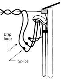
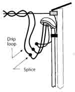
If it is impossible to locate the service head above the insulators, be sure to provide drip loops (see Fig 8—19) to keep rain out of the cable. Your power supplier may connect the ends of the wires in the cable to the service-drop wires, although local service policies vary. In some jurisdictions, particularly on upgrades of smaller residential services, the electrician on site must do the cut and reconnection. Because the service drop will be live, this is potentially dangerous work for an unqualified person to perform.
Support the cable within 12 inches of all terminations, and additionally every 30 inches using straps like those shown in Fig. 8—16. Run the bottom end of the cable into the meter socket, again twisting the neutral strands into a single wire. Use the same procedure to go from the socket to the service equipment. Make the connections as shown in Fig. 8-20, landing the twisted neutrals on the center contacts.
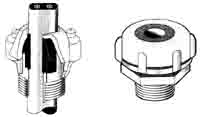
Separate wires in raceway (conduit) Instead of service entrance cable, separate Type TW, THW, RHW, TFIWN, or XHI-1W wires inside raceway may be used. The neutral wire is always white (or re-identified as such using paint or tape at terminations); in some localities bare uninsulated wire is used. The other two wires are black, or black and red. To determine the site raceway required, see Tables 1.4, and 5 in Section 9 of the NEC. Common raceway’s include rigid or intermediate metal conduit, rigid nonmetallic conduit, and electrical metallic tubing, all described in Section 12. Cut pieces as long as required and prepare them in the manner described in Section 12 depending on the type used. At the top of the raceway install a service head of the type shown on the right in Fig. 8—21. At the point where the raceway is to enter the house, use an entrance cli such as shown on the left in Fig. 8—21. This has a removable cover which makes it easy to help the wires around the sharp bend while pulling them into the raceway. Be sure to get one large enough, as covered in the next topic.
After the raceway itself is completely installed, pull the wires into it. For the relatively short lengths involved, the wires can usually be pushed in at the top and down to the meter socket; from there, other lengths are pushed through to the inside of the house. If the raceway is long or has bends in it, use fish tape to pull the wires through. See Fig. 12-11 and related text for how to use fish tape. A length of galvanized clothesline or similar wire will serve the purpose for short lengths. Conduit bodies : At the point where the raceway enters the building (which would correspond to the location of the sill plate), it is customary to use an entrance conduit body of the type shown in Fig. 8-21. With the cover removed, it is a simple matter to pull wires around the right-angle corner. Be careful to observe the sizing rules in NEC 314.28(A)(2) and (3) in choosing this fitting. The distance between the center of the conduit stops (roughly equal to the long dimension of the cover) must not be less than 6 times the trade diameter of the entering raceways, or a full 12 inches in the case of trade size 2 raceway. The distance between the conduit stop in the short dimension and the inside of the cover must at least equal the minimum bending radius for the size of conductors used, based on NEC 312.6(A). For 3/U copper conductors, rated 200 amps, that dimension is 4 inches. Conduit bodies (which generally look like the letter “L”; those with the opening in the back are called “LB”) that meet these spacings are generally referred to as “mogul” fittings; conventional conduit bodies won’t meet NEC requirements. The only other option is to see if a conduit body of smaller dimension has been listed for a conductor fill that meets your needs. For example, there are no “mogul” rigid non-metallic conduit bodies, so (if listed to U.S. standards) they are all routinely investigated for allowable wire fill. Look for a “3 4/0 XHHW MAX” or similar marking. If you aren’t using XFIHW wires, or if you’re using combinations of sizes, just compare the actual cross-sectional area of the conductors with the area represented in the listing instructions. This fitting also must be rain-tight and arranged to drain; drill a small weep hole in its bottom end before you pull the wire. After completing the pull, and assuming the raceway passes from the outdoors to an indoor location with air that can be significantly warmer or cooler than outdoor air, stuff some sealing putty around the wires where they enter the raceway. This will obstruct the circulation of humid air to a point where condensation could occur at the colder end. The NEC has routinely enforced this principle on raceways passing from cold storage areas into warm rooms, for example, but the 2002 NEC expanded on this principle, directly applying it to raceways (or cable sleeves) “passing from the interior to the exterior of a building: Concentric knock outs: The cabinets of service switches or circuit breakers are too small to permit knockouts of all the sizes that might be required in all circumstances, so concentric knockouts are provided (Fig. 8—22). Remove the center section if you need the smallest size; remove the two smallest sections for the next size, and so on. Be very careful to remove only as many sections of this intricate knockout as required for your particular installation.
MAKING GROUND CONNECTIONS The service switch or circuit breaker has two heavy terminals to which the two incoming hot wires are connected. It also has a neutral busbar on which you will find several large connectors and a number of smaller terminals. Connect the incoming white or bare neutral to one of the large connectors, and the ground wire to the other. The smaller terminals are for the white wires of the individual circuits or feeders. If there are enough terminals, bare grounding wires of circuits can also be connected to the neutral bar in service equipment if acceptable to the inspector. If additional terminals are required, an accessory equipment grounding bar must he used. The enclosure will have mounting means for this ground bar. Solid neutral : Whether your service equipment contains breakers or fuses, the incoming neutral wire must never be interrupted by a breaker or fuse. Therefore in a three-wire, 120/240-volt installation, while there are three service-entrance wires, the main breaker is only a two-pole, and in fused equipment there are only two main fuses. The neutral is call a “solid neutral”—a neutral not protected by breaker or fuse. Such equipment then is called “three-wire SN”. Grounding : Every installation of the types discussed in this hook must be grounded. The technical reasons for grounding are discussed in Section 7. A good, carefully installed ground is absolutely necessary for a safe installation. Grounding is accomplished by running a ground wire from the incoming neutral service wire (from a point where it is connected to the neutral busbar in the service equipment) either to an existing grounding electrode system or, if not available, to a grounding electrode specifically installed and connected for this purpose. Grounding electrode system : All of the following which exist at the structure must be bonded together to form a grounding electrode system; in addition, any existing rod, pipe, or plate electrodes must be included with these:
If only one of the above exists it may serve as the grounding electrode, except for water piping which must be supplemented by at least one other electrode. If none of these is available, use a rod, pipe, or plate electrode. Rod, pipe, or plate electrodes, or other underground systems or structures : If there is no underground water system, a good ground becomes a problem. If none of the above options for a grounding electrode system is available, the NEC allows for several alternatives that may serve as the grounding electrode:
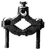
Ground rod installation is discussed in a later section. If a ground rod alone is used, the ground wire never needs to be larger than 6 AWG regardless of the size of the wires in your service equipment. The NEC requires rod, pipe, or plate electrodes to have a ground resistance or 25 ohms or less, if only one is installed. If the resistance rule cannot be met with a single such electrode, then an additional electrode must be installed. When more than one electrode is installed, the NEC effectively declares that you have tried hard enough, and does not insist on meeting the 25-ohm limit. There are many areas of the country where soil conditions routinely produce resistances in the hundreds of ohms. Check with local authorities to get a sense of local conditions. Many installers routinely install two such electrodes as a matter of course, avoiding the need for measurements. Be sure they are at least the NEC minimum of 6 feet apart, and even farther if possible. Bonding the busbar : Service equipment cabinets contain a copper neutral busbar on which are installed several large solderless connectors for the heavy incoming neutral wire and the ground wire, plus as many smaller connectors or terminal screws as nee one for the grounded wire of each 120-volt circuit. As purchased, the neutral busbar may be insulated from the cabinet. If you use this equipment as service equipment you must bond the neutral busbar to the cabinet. It must not be bonded if the breaker or switch is used, for example, as a disconnecting means for an appliance or other load, or is used as a panelboard on the load side of a service. If you have to bond the busbar to the cabinet, it is a simple matter. In some brands of equipment the neutral busbar is provided with a green bonding screw that you must tighten securely. In other brands, the cabinet will contain a flexible metal strap that is already bonded to the cabinet, and you must connect its free end to one of the connectors or screws on the neutral busbar. The equipment grounding busbar will always be bonded to the enclosure, whether within the service equipment enclosure or at a remote panelboard. Installing the ground wire: There is never more than one ground wire from the service to the grounding electrode(s). There is no objection to using insulated wire, but bare wire costs less and is usually used for the ground wire. Keep the ground wire as short as possible. All grounding connections to the water pipe must be made within the first five feet of where the water pipe enters the building. Size : The minimum ground wire size is based on the size of your service wiring. Larger size ground wire is optional. With 2 AWG or smaller service wires, 8 AWG is permitted for the ground wire but it must be enclosed in armor or conduit. It is more economical and practical to use 6 AWG because it doesn’t have to be so heavily protected. With I or 1/0 AWG service wires, 6 AWG is the minimum ground wire size. With 2/0 or 3/0 AWG service wires. 4 AWG is the minimum ground wire size. If you are using aluminum service wires, the equivalent cut points are 1/0 AWG or smaller, 2/0 or 3/0 AWG, and 4/0 AWG or 250 kcmil. Aluminum ground wires are also permitted. The NEC sizing rules extend to all service sizes, as covered in NEC Table 250.66. Armor or conduit is not required for 6 AWG or 4 AWG ground wire. Either size must be fastened with staples to the surface over which it runs. It must he installed in a way that minimizes danger of physical damage after installation. Physical protection for the ground wire can also be provided by rigid nonmetallic (PVC) conduit. Connecting : At the service equipment. connect the ground wire to the neutral busbar to which you have connected the neutral of the service. Run it to the grounding electrode(s), and there connect it to a ground clamp of the general style shown in Fig. 8-23. This clamp must be made of galvanized iron if installed on an iron pipe, but copper or bronze if it runs to a copper pipe or rod.
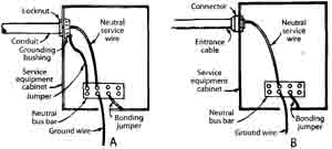
Bonding at the service entrance : A careful job of bonding is essential to assure effective grounding. Caution: When using either armor or conduit to protect the ground wire, great care must be taken to securely and permanently bond the armor or conduit at both ends—to the cabinet and to the ground clamp at the electrode. Unless this is done, the resulting ground will be much less effective than when using unprotected wire. This means using a ground clamp that secures both the raceway and the wire inside it simultaneously. At the service equipment, use a bonding procedure similar to that shown in A of Fig. 8-24 for the service conduit.
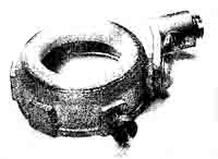
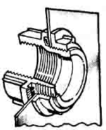
Service-entrance wires If your service-entrance wires are in conduit, follow A of Fig. 8—24. Install a grounding bushing (Fig. 8—25) on the end of the conduit inside the cabinet and run a jumper (bare or insulated, of the same size as the ground wire) from the bushing to the neutral busbar (grounding busbar, if downstream from the service). The screw of the bushing bites down into the metal of the cabinet, contributing toward a good continuous ground and preventing the bushing from turning and loosening, which would impair the continuity of the ground. If your service uses service-entrance cable with a braided neutral, as in Fig. 8—12, the grounding bushing is not required; follow B of Fig. 8—24. When you use a threaded hub bolted to the enclosure, or a hub of the two-piece type shown in Fig. 8—26, bonding of the conduit to the enclosure is automatic and the grounding bushing and jumper are not necessary.
Ground wire : If you use armored ground wire, bond the connector on the cable to the cabinet, and at the electrode use a ground clamp similar to the type shown in Fig. 8—23; connect the wire to the terminal screw, and clamp the armor in the separate clamping device of the ground clamp. If the ground wire is protected by conduit, bond the conduit to the cabinet with a locknut and grounding bushing. A jumper from that bushing to the neutral busbar is required, as shown for the service conduit in A of Fig. 8-24. Use a ground clamp into which you can thread the conduit, and connect the ground wire to a terminal screw of the clamp. If the ground wire is protected by rigid nonmetallic (PVC) conduit, bonding of the raceway is not necessary.
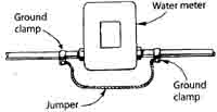
Water meter : A bonding jumper must be installed around the water meter as shown in Fig. 8—27. Use two ground clamps and a length of wire of the size used for the ground. This prevents the ground from being made ineffective if the water meter is removed. Some water meters also have insulating joints. Use the same procedure around other insulated interruptions in the continuity of the water piping system, such as a water filter with plastic housings, even if the grounding connection is on the street side of such interruptions. Water piping systems must be bonded to the ground wire, and this often means looking in both directions from the ground clamp in order to find discontinuities.
EMERGENCY BACKUP GENERATORS There maybe times when the main power supply is cut off due to a storm or other factors. If you live far from town, or in a lightning-prone area, your electric service maybe subject to occasional or frequent outages. Experience will tell you whether a generator would be a good investment for you. Choice of a portable or permanently installed type will depend on your particular needs. Fuel types include gasoline, natural gas, diesel fuel, or liquid propane. Be sure to check local requirements for storage of fuel and the noise level permitted. Portable or permanently installed? Small portable generators can he used to power a few individual appliances such as the refrigerator, freezer, and a lamp or two. Be sure the extension cords you use to connect the appliances to the generator are sued to carry the specific loads. Check the watts/volts ratings on the nameplates of the appliances and on the extension cords. For convenience you may want a permanently installed generator. There arc systems that automatically start the generator when the normal power source fails, and automatically transfer the load(s) but for the ordinary residential situation a system for manually starting the generator and transferring the load(s) will usually suffice. Choosing the correct size : Generators arc rated and priced according to the wattage they produce. Noise level and rate of fuel consumption (running time) are other factors to consider in making a selection. The size you need depends on whether you want to have the load of the entire house or farm on during an outage, or only a few selected circuits. A limited amount of rewiring might be required in order to separate the circuits for your essential equipment from the rest of the load, or in the case of a farm, the selected loads from the total load. If in doubt about how to proceed, consult with a professional. Later, we will present information on the calculation of residential and farm loads. For motors, multiply the horsepower by 746 to convert to watts. Use a generator with 25 percent capacity above the proposed connected load to permit motors to start. If your load includes hard-to-start motors, such as a well pump, it would be prudent to size the generator capacity to as much as three times the connected load in order to permit the motor to start. If some of the load is 240-volt, be sure the generator you choose will supply 240 volts, and not 120 volts only. A generator that is automatically started must be sized large enough to carry the entire load connected to it, startup as well as continuing. With a manually started generator you can turn off all equipment before starting the generator, and then restart selected equipment individually to minimize the load. Isolate generator from main power supply : It is absolutely necessary that it not be possible for your generator and the incoming lines from the power supplier to he connected together. The principal reason for making sure your generator is isolated from the power supplier’s lines is to protect the workers who are out on the power supplier’s system trying to restore power—they could receive a serious shock or be electrocuted by current coming from your generator. Never attempt to energize wiring in a building by using an extension cord with two male plug ends, or you will potentially create this and a number of other problems. The NEC requires that a sign be placed at the service location advising of the presence of the standby source. Another reason for keeping your generator separate is to avoid damage to it and your wiring and appliances. Sophisticated equipment would be required for your generator and the power supplier’s system to work together, because they would have to match exactly in voltage and frequency. The required separation of generator and power supplier’s lines can be accomplished with a properly installed transfer switch that meets the requirements of the NEC. Check with a professional or with your power supplier for information about such transfer equipment. Transfer switches feed a given load from either of two alternate sources. The proper procedure involves the use of an additional panelboard containing the circuits that arc to he kept live during the period when the local power supplier is experiencing an outage, and feeding this panel from the transfer switch. Then connect a feeder from the usual service panelboard to one side of the transfer switch, and the line that will connect to the generator on the other side. If the generator is portable and not permanently connected, use a plug-and-receptacle type of connection so you can make the connection easily and quickly. However, in this case the receptacle body must go on the end of the cord from the generator. This means the “plug” (the device with the male blades) must he at the building wall. These devices are called “flanged inlets” and although recessed into a wall, they have male blades, as shown in Fig. 8-28. This arrangement prevents plug blades from being fully exposed and energized while the generator is running.
Grounding the generator : The generator frame must be grounded to the same electrode as that used for the service. If the generator is not permanently installed, hut moved into position when needed, be sure there is a reliable means to accomplish this grounding, such as a flexible cable and a ground clamp, whenever the generator is in use. Be sure that after the transfer to the generator the identified (white, neutral) wire is still bonded to the grounding electrode. PREV: Grounding for
Safety Home • • |
Thursday, 2016-12-29 7:50 PST
