|
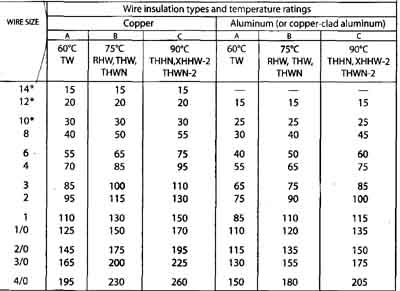
Overcurrent devices such as fuses and circuit breakers limit the amperage in any wire to the maximum that is permitted by the Notional Electrical Code (NEC). If more than the permissible maximum amperage is allowed to flow, the temperature of the wire goes up and the insulation may be damaged, leading to shortened life and accidental grounds that can become dangerous. If the overload is great enough, there is danger of fire. The maximum amperage established by the NEC as safe for any particular kind and size of wire is called the ampacity. Table 4-1 lists the ampacity of common wires. OVERCURRENT DEVICESAny overcurrent device you use must have a rating in amperes not greater than the ampacity of the wire that it protects. For example, if 12 AWG wire has a calculated ampacity of 20 amps, the circuit breaker or fuse that you use to protect the wire must have a rating not greater than 20 amps. When two different sizes of wire are joined together ( For example, when 8 AWG is used for mechanical strength in an overhead run to a building where it’s joined to 14 AWC for the inside wiring), the overcurrent protection must be the right size for the smaller of the two wires. A fuse or circuit breaker of the correct size for the larger wire may be used at the starting point, provided another one of the proper size for the smaller wire is used where the wire is reduced in size. An example is when a wire such as 8 AWG, with an ampacity of 40, runs from one building to another where it feeds several 15-amp circuits (see Fig. 5-1). Fig. 5-1 : If fuses are used where the wire size is reduced, select a fuse size that protects the smaller wire. What do you do when a fuse blows or a circuit breaker trips? Most people will say to install a new fuse or reset the breaker. That’s correct—hut first find out what caused the blown fuse or tripped breaker. Fuses and circuit breakers are the safety valves of electrical installations. Using substitutes or fuses too large for the size of wire can be dangerous because it could lead to a fire. Section 19 explains how to troubleshoot a blown fuse or tripped circuit breaker. Fuses: A fuse is nothing more or less than a short piece of metal of a kind and size that will melt when more than a predetermined number of amperes flows through it. This metal link is enclosed in a convenient housing to prevent hot metal from spattering if the fuse blows and to permit easy replacement. A fuse rated at 15 amps is tested to carry 15 amps. When more than 15 amps flows through it, the wire inside the fuse melts (the fuse “blows”), which is the same as opening a switch or cutting the wire. The greater the overload, the quicker the fuse will blow. Plug fuses: The common plug fuse, shown in Fig. 5-2, is made in ratings up to 30 amps. It’s known as the Edison-base type because the base is the same as on ordinary lamps. These fuses are not permitted in new installations. They may be used only as replacements, and then only when there is no evidence of tampering or overfusing (using a fuse ton large for the size of wire involved). For new installations, see the entry for Type S non-tamperable fuses. Plug fuses are rated at 125 volts, but may be used on a system having a grounded neutral and no conductor over 150 volts to ground, so they could be used for a 240-volt load served from a t20/240 volt, three-wire system. Fig. 5-2: Edison-base plug fuses are made only in ratings up to 30 amps. They are not permitted in new installations. Time-delay fuses: When a motor is started, fuses often blow because a motor that draws only 6 amps while running may draw as much as 30 amps for a few seconds while starting. An ordinary fuse carries 80 percent of its rated amperage indefinitely, hut blows very quickly if twice that amperage flows through it. However, wire that can safely carry 15 amps continuously—but might be damaged or even cause a fire if 30 amps flowed continuously—will not he damaged or cause a fire if 30 amps flows for a few seconds. The “time delay” type of fuse takes advantage of the ability of wire to carry a higher load momentarily. Commonly called by the trade name “Fusetron” although there are other brands, it looks like an ordinary fuse but is made differently inside. It blows just as quickly as an ordinary fuse on a small continuous overload or on a short circuit, but it will carry a big overload safely for a fraction of a minute. This type of fuse is convenient where motors are used because it prevents needless blowing of fuses and eliminates many service calls. Edison—base time—delay fuses are not permitted iii new installations. They are permitted as replacements only and then only, if there is no evidence of over-fusing or tampering. For new installations, see the entry for Type S non-tamperable fuses. Type S nontamperable fuses: The NEC requires the use of type S fuses in all new installations that use fuses and for replacements if there is evidence of tampering or over-fusing. Since all ratings of ordinary Edison-base plug fuses are interchangeable, nothing prevents someone from using, For example, a 25-amp or 30-amp fuse to protect a 14 AWG wire, which must be protected at not over 15 amps. To prevent this unsafe practice, the nontamperable fuse was developed (see Fig. 5-3). The NEC calls this a ”Type 5” fuse, but it’s commonly called by the trade name ”Fustat”. The fuse itself won’t fit an ordinary fuseholder, so an adapter (shown at left in the illustration) must first he installed in the ordinary fuseholder; once installed, it cannot be removed. There are three sizes of adapters. As a safety measure, the 15-anip will accept only 15-amp or smaller fuses; the 20-anip will accept only 16-amp through 20-amp fuses; the 30-amp will accept 21-amp through 30-amp fuses. Type S fuses are presently made only in the time-delay type. They are rated at 125 volts, but may be used on a system having a grounded neutral and no conductor over 150 volts to ground, so they could lie used for a 240-volt load served from a 120/240 volt, three-wire system. Fig. 5-3: A typical Type S nontamperable fuse (center, and cross section at right) and its adapter (left). Once an adapter has been screwed into a fuseholder, it cannot be removed. This prevents the use of fuses larger than originally intended. A word of caution when using Type S fuses—when screwing the fuse into its holder, turn it sonic more after it appears to he tight. Under the shoulder of the fuse there is a spring—the fuse must he screwed in tightly enough to flatten the spring or the fuse won’t “bottom” and you will have an open circuit just as if the fuse were blown. Cartridge fuses: This type is made in all amperage ratings. Those rated at 60 amps or less are of the ferrule type shown in Fig. 5-4. Those rated at 70 amps or more have knife-blade terminals as shown in Fig. 5-5. The cartridge fuses of the type illustrated may be used in any circuit of up to 250 volts between conductors. Cartridge fuses are used for loads of 30 amps and higher such as mains, dryers, ranges, resistance heaters, and water heaters. Fig. 5-4: Cartridge fuses rated 6g amps or less are of the ferrule type shown. Fig. 5-5 : Cartridge fuses rated more than 6tt amps have knife-blade terminals as shown. Circuit breakers : In new residential construction, circuit breakers are generally installed, with fuses appearing mostly in existing installations. A circuit breaker looks like a toggle switch. Figure 5-6 shows a single unit. Inside each breaker is a fairly simple mechanism which in case of overload trips the breaker and disconnects the load. If a breaker trips because of overload, in most brands you must force the handle beyond the OFF position, then return it to ON to reset it. On sonic brands, the handle merely goes to the OFF position and is reset by returning it to the ON position. A circuit breaker has a definite time delay. It still carry 80 percent of its rated load indefinitely, a small overload for a considerable time, arid will trip quickly on a large overload. Nevertheless, it will carry temporary overloads long enough to permit motors to start. Fig. 5-6 : A single circuit breaker (left) and method of resetting the breaker if it trips. FEEDERS AND BRANCH CIRCUITSIn larger homes, it may be advantageous to locate an additional panelboard near a concentration of required branch circuits, particularly in cases where that load is sonic distance from the service equipment. For example, if the kitchen were on the other side of the house from the service entrance, you might decide to place a panelboard in the basement under the kitchen. In doing so, you should supply this additional panelboard with a large circuit capable of supplying the calculated load of the individual branch circuits connected at this point. For example, you might install a 60-amp circuit breaker in the service panelboard, arid then run a 6 AWG cable or wires in a raceway to the location of the smaller panelboard. This would he a practical application of the concept illustrated in Fig. 5-1. The official NEC term for the conductors extending between a service or other source of supply and the final branch-circuit overcurrent device is feeder. The remote panelboard is often referred to as a “sub-panel”. Sonic time ago the NEC removed this term throughout the NEC, but it widely persists in the vernacular of the trade. Google “Grounding Basics”. In general, feeders must have their grounded conductors (white wires) insulated from their equipment grounding conductors (hare or green wires); Google “bonding the busbar” for more info. This means that for a 240-volt feeder, there will usually be four wires, comprised of two ungrounded conductors (often black, or black and red), a neutral (white), and an equipment ground (a white or green wire). If the feeder is wired with a metal raceway such as EMT that qualifies as a grounding conductor, the separate fourth wire may be omitted. Note that the judicious use of a feeder can reduce voltage drop, because the portion of any total circuit run from the service to the outlet that is taken up in a feeder occurs over a larger conductor with less resistance per unit length. The remote panelboard may also he located in a more convenient location. However, the requirement for appropriate workspace about the remote panel is the same as that for the service panelboard. Review the topic “Service equipment location” in Section 8 for more details. CALCULATING BRANCH CIRCUIT NEEDSIf all the lights and appliances in a home or on an entire farm were protected by a single fuse or circuit breaker, the entire establishment would be in darkness when that breaker tripped or the fuse blew. Also, all the wires would have to be very large to match the ampere rating of that breaker or fuse, which would make a clumsy and expensive installation. Therefore the different outlets in an installation are separated into smaller groups known as branch circuits. Inexpensive 14 AWG or 12 AWC wire is used for most of the wiring, protected by b-amp or 20-amp breakers or fuses. When one of these breakers trips or a fuse blows, only the outlets on that circuit are dead; those on other circuits are still live. Continuous loads : See the discussion under “Water heaters” in “Appliances”. Outlets per circuit : In residential work, the NEC does not limit the number of lighting outlets placed on one circuit. But if you put too many, you will probably have trouble with breakers tripping or fuses blowing. In most cases, it’s best to connect fewer than a dozen outlets on one circuit even if more are permitted. Note : An outlet is any point where electric power is actually used. Each fixture, even if it has five lamps, is considered one outlet. Each receptacle outlet, even the duplex type, is one outlet. Switches are not outlets since they use no electric power, but merely control its use. But in estimating the cost of an installation, switches are included in counting the outlets to arrive at a total cost on the “per outlet” basis, though this is not in accordance with the NEC definition Many electricians quote on a “per opening” basis to avoid this terminology problem. Kinds of circuits : The circuits used in homes can be divided into the following three general types : lighting circuits—primarily for lighting and serving permanently installed lighting fixtures, as well as receptacle outlets into which you plug lamps, radios, televisions, clocks, and similar 120-volt loads (but not kitchen appliances); small appliance circuits—receptacles in kitchen, dining room, etc. for such items as coffeemaker, toaster, electric fry pan; individual appliance circuits—each serving a single appliance such as a range, water heater, clothes washer or dryer; circuits may be either 120-volt or 240-volt. In addition, there may be a need to add a circuit for a permanently connected motor that is not part of an appliance, such as might be used with certain shop tools. (Motor types and installation are discussed here.) Lighting circuits : The NEC requires enough lighting circuits to provide 3 VA of power for every square foot of floor space in the house. Since a circuit wired with 14 AWE; wire and protected by 15-amp overcurrent protection provides 1,800 VA (15 x 120 = 1,800), each circuit is enough for 600 square feet (1,800 / 3 = 600). This is the NEC minimum. The NEC concerns itself with safety only. To allow for convenience and usefulness over time, it’s wise to provide one circuit for each 500 square feet of space. What is included in the square footage of a house when calculating the number of lighting circuits needed? Open porches and garages, even if attached to the house, are not included in the total. But unfinished or unused spaces that are adaptable for future use must be included according to the NEC. Run a special circuit to such an area, terminate it in a single outlet if you wish, and later branch off from that outlet to the additional outlets that you want when you finish off the space. If the space is large, run two circuits. To arrive at the NEC definition of the total number of square feet for determining the number of circuits, multiply the length of the house by its width. If its outside dimensions are 30 x 45 feet, then one floor represents 1,350 square feet (30 x 45 = 1,350). If the basement is finished or can be finished into usable space, add its area of, For example, 24 x 30 or 720 square feet to the first-floor area of 1,350 square feet for a total of 2,070 square feet. If an upper floor has unfinished space that can later be finished into a bedroom, add its area. Then divide the total area by 600 to arrive at the minimum number of lighting circuits the NEC requires, or divide by 500 for a more adequate installation. In Table 5-1, minimum and recommended numbers of lighting circuits are calculated for some typical square footages. Special small-appliance circuits : The circuits already discussed are for lighting, including floor and table lamps, and items such as radios, TVs, and vacuum cleaners. These circuits don’t permit proper operation of larger kitchen and similar appliances that consume much more power. NEC 2 10.52(B) requires two special small-appliance circuits to serve only small-appliance outlets, including refrigeration equipment, in the part of the house occupied by kitchen, pantry, breakfast room, and dining room. Both Circuits must extend to the kitchen; the other rooms may be served by either or both of them. The circuits must be wired with 12 AWG wire protected by 20-amp circuit breakers or fuses. No lighting outlets may be connected to these circuits (with two exceptions : a combination receptacle! support for an electric clock in kitchen or dining area, and a receptacle serving the ignition system, oven light, and/or timer for a gas-fired cooking appliance). Either 15-amp or 20-amp 125-volt rated receptacles may be installed on these 20-amp circuits. Each such circuit has a capacity of 2,400 VA (20 X 120 = 2,400), which is not too much considering that toasters, irons, and similar appliances often require 1,000 watts, and appliances such as roasters and toaster ovens may consume over 1,500 watts. These two circuits can be merged into one multi-wire circuit. At least one separate 20-amp circuit must be run to laundry appliances, and another one to all the bathroom receptacles. A separate 15-amp branch circuit is permitted to serve refrigeration equipment. Individual circuits : It’s customary to provide a separate circuit for each of the following (and required for central heating equipment): • Self-contained range • Separate oven, or counter-mounted cooking unit itt Water heater • Clothes washer • Clothes dryer • Waste disposer • Dishwasher • Motor (and fan) on oil-burning furnace • Motor on blower in gas furnace • Water pump • Permanently connected appliances rated at more than 1,000 watts (example : a bathroom heater) • Permanently connected motors rated more than 1/8 hp Note that on general-purpose branch circuits (those supplying two or more receptacles or outlets for lighting or appliances), the maximum load of utilization equipment fastened in place (other than fixtures), such as exhaust fans, garage door openers, etc. cannot exceed 50 percent of the branch circuit rating. This is often the deciding factor in whether or not to run an individual circuit. Appliance and motor circuits maybe either 120-volt or 240-volt depending on the particular item installed. Google for instructions on how to label every circuit at the panelboard to assist in troubleshooting. Table 5-2 : DETERMINING CORRECT AMPERAGE FOR MOTORS Table 5-3 : SUGGESTED NUMBER OF 120-VOLT AND 240-VOLT CIRCUITS Motor circuits : Separate circuits are recommended for individual motors over 1/4 hp that are not part of an appliance. Such motors might be either directly connected (example : sump pump) or belt-driven (example : bench grinder). Determine the m amperage from Table 5-2, ad from NEC Table 430.148. Total number of circuits : You must decide for yourself how many circuits you will need. Provide circuit breakers or fuses for specific appliances even if you don’t intend to install such appliances until later. Even then, provide for some spare circuits. For a new wiring installation, follow the suggestions in Table 5-3 for calculating the total number of 120-volt and 240-volt circuits needed based on the square footage of usable area. Arc-fault circuit interrupters (AFCI) : The U.S. Consumer Product Safety Commission estimates that annually there are more than 40,000 fires in residential occupancies, resulting in 250 lives lost and $1 billion in financial loss. It has been estimated that 40 percent of these fires are caused by arcing faults—the unwanted flow of electricity through an insulating medium (such as air). An arc can generate enough heat to be a source of ignition, but not enough current to trip the standard circuit breaker. Just as there are circuit breakers incorporating ground-fault protection for the purpose of preventing people from receiving dangerous shocks, there are now circuit breakers incorporating arc-fault circuit interruption in addition to the normal overcurrent functions, and some that incorporate both GFCI and AFCI in the same breaker frame. Arcing faults exhibit a characteristic current and voltage pattern that can be detected by the electronics in the AFCI which then interrupts the circuit. AFCI protection must now be arranged (NEC 210.12) for all circuits supplying bedroom outlets, even smoke detectors and lights. This new rule (effective for all bedroom receptacle outlets January 1, 2002 , and then for all other bedroom outlets effective with the date of local adoption of the 2002 NEC) is controversial because of restrictions placed on these devices by their manufacturers. Most (but not all) AFCI circuit breakers cannot be used on multi-wire branch circuits, and some AFCI circuit breakers are restricted by the terms of their listing instructions from being used on wiring methods without an equipment grounding conductor (refer to the continuous grounding). This means that if existing wiring to bedrooms involves either of these relatively common wiring arrangements, you should discuss with the local inspector the extent to which this rule will be enforced on existing circuits. Multi-wire circuits are very common, and many homes wired before the early 1960s have at least some branch circuits that have no equipment grounding conductor. Some receptacles are “listed to provide protection of the entire branch circuit” if they are installed at the first outlet in the branch circuit. These devices, likely to be available the second half of 2009, are additionally tested for use on branch circuits that don’t have a grounding conductor. As the industry gets up to speed on the full ramifications of the 2009 requirements in this area, look for a steady evolution in the ways these devices can be installed. PREV: Wire -- Selecting
and Connecting Home • • |
Sunday, 2013-06-30 14:29 PST