Circuit Diagrams
Home|
Before you can wire a building, you must learn how switches, receptacles, sockets and other devices are properly connected to each other with wire to make a complete electrical system called a circuit—the path along which current flows. GROUNDED WIRES In residential and farm wiring one of the current-carrying wires is grounded, which means it is connected to an underground metal water pipe system and to a driven ground rod. Many people refer to the grounded wire as the neutral wire. Sometimes it is a neutral and sometimes it is not. Ungrounded wires are known as “live” or “hot” or “energized” wires, which means they have a voltage, in house wiring usually 120 volts, above zero (ground potential—the earth is assumed to be at zero potential). It is essential to remember these five points about grounding: • The grounded wire is white in color. Two recognized alternatives to white for the grounded conductor are: gray (caution: white is preferred, and for many years gray theoretically could have been and occasionally was used for ungrounded conductors); or three white stripes on any color insulation except green. • The grounded wire must run direct to every 120-volt device or outlet to be operated (never to anything operating only at 240 volts). • The grounded wire is never fused or protected by a circuit breaker. • The grounded wire is never switched or interrupted in any other way. • White wire must never be used except as a grounded wire. Other wires are usually black but may be some other color, but not white or green. The white wire must run to every 120-volt device or outlet other than a switch; the other wire to the device is usually black but may be some other color, but not white or green. White wire can be used for ungrounded purposes when it is part of a cable assembly brought to a switch or for a 240-volt load, but even here it must be re-identified as other than white at all visible points and at terminations. Examine a socket or similar device carefully and you will find that one of its two terminals is a natural brass color, and the other is silver-colored (usually nickel-plated) and called “white” by the NEC. The white wire must always run to the white terminal. In the case of sockets, the white terminal is always connected to the screw shell and never to the center contact of the socket. Switches never have white terminals. WIRING DIAGRAMS Wiring diagrams are used in planning electrical installations. Diagrams are useful for planning safe and efficient installations, and for clarifying details such as the wiring of three-way and four-way switches.
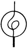
Diagram symbols : For any circuit, two wires must run from the starting point to each outlet serving electrical equipment (lamp, motor, etc.). Imagine that the current flows out over the black wire to the equipment, through the equipment, and back to the starting point over the white wire. In this guide, the starting point is called the SOURCE, and a lamp symbol (FIG. 6-1) is used to indicate the equipment to be operated. Figure 6-2 illustrates the method used to indicate whether or not crossing wires are connected to each other. In all diagrams wires are indicated like this:
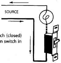
The fact that one line is heavier than the other does not mean that one wire is larger than the other; both are the same size. Adding switches : The simplest possible diagram is that of FIG. 6-3, a lamp that is always on with no way of turning it off. Such a circuit is of little value, so you should add a switch. Figure 6-4 shows how you simply make the black wire detour to a switch. An unenclosed switch is shown so you can see how it operates: opening (turning off) the switch is the same as cutting a wire. Of course, unenclosed switches are unsafe and not permitted. Figure 6-5 shows the same circuit but with an enclosed flush toggle switch which serves the same purpose, but is much neater, more convenient, and safer to use.
FIG. 6-4 : The circuit of FIG. 6-3 plus an open switch.
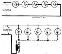
Wiring in parallel : If several lamps are used, do not make the mistake of wiring them in series as in FIG. 6-6 because that is impractical for most purposes. If one lamp burns out or is removed from its socket, it is the same as opening a switch in the circuit -- all the lamps go out. Instead, wire them in parallel as in FIG. 6-7. The white wire goes to each lamp, from the first to the second and to the third and so on; the black wire also runs to each lamp in similar fashion. Each lamp will light even if one or more of the others is removed. The switch shown cuts off the current to all the lamps at the same time. The wiring is simple: white wire from SOURCE to each socket or outlet; black wire from SOURCE to the switch, and from the switch another black wire to each of the sockets. This is the way a fixture with five sockets is wired.
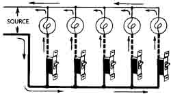
FIG. 6-7 : Style of wiring known as “parallel” wiring. It is used for all ordinary purposes. If each lamp is to be controlled by a separate switch, use the FIG. 6-8 diagram. The white wire always runs from SOURCE to each lamp; the black from SOURCE to each switch, and from each switch a black wire runs to the lamp that it controls. If you trace the current from the SOURCE over the black wire through each switch, one at a time, along the black wire to the lamp, and back from the lamp to the SOURCE, you will find that each lamp can be independently controlled.
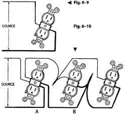
Wiring receptacle outlets : The wiring of plug-in receptacle outlets is simple. If there is only one receptacle, run the white wire from the SOURCE to the side of the receptacle that has white (silver-colored) terminal screws, and run the black wire to the other side, as in FIG. 6-9. If there are several receptacles, as in FIG. 6-10, run the white wire to one side of the first receptacle, from there to the second receptacle, and so on; do the same with the black wire. Figure 6-10 is the same parallel wiring diagram as FIG. 6-7 except that receptacles have now been substituted for lamps and the switch has been omitted.
Where the two wires shown in FIG. 6-10 are part of a three-wire circuit, it is not permitted to feed the white conductor through by using the two screws on the side of the receptacle, as shown at A, because removing this receptacle could place 120-volt loads in series on 240 volts, with possibly disastrous results. Instead, a splice is required with a pigtail going to the receptacle as shown at B. Many inspectors require pig-tailing at all feed-through receptacles even though the devices are tested and listed to be connected as shown at A. (See FIG. 4-15 for another illustration of a pigtail splice.) Wiring outlets controlled by pull chains : There are few locations where a pull chain will be used, since lighting in attics and under-floor spaces used for storage or for equipment requiring servicing must be controlled by a wall switch at the entry to the space. To wire for a pull chain, substitute a pull-chain socket for the receptacle in FIG. 6-9. Combining several diagrams : When several groups of outlets are to be wired, the two separate wires from each group can be run back to a common starting point where the wires enter the house, as shown in FIG. 6-11 where the diagrams of Figs. 6-5, 6-7, and 6-8 have been combined. This method requires a consider able amount of material because the wires must be much longer than necessary. It is more efficient just to wire the first group, then run wires from the first group to the second, and from the second to the third, as in FIG. 6-12 which shows the same three groups but using less material.
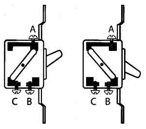
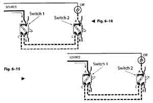
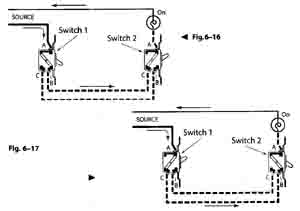
In other words, here they form one circuit. This still uses a great deal of material. To reduce the amount required, the circuit can be arranged as the next diagram shows. The white wire may be extended at any point to the next outlet. The black wire likewise may be extended at any point, provided that it can be traced all the way back to the SOURCE without interruption by a switch. In other words, in these diagrams a black wire can be extended from any black wire indicated by the solid heavier lines, but not from the black wire between a switch and an outlet indicated by a heavy broken line. Thus, in FIG. 6-12, A and B are the starting points for the second group, and C and D are the starting points for the third group of lights. Three-way switches : The switch used for controlling a light from one point is known as a “single pole” switch. “Three way” switches allow you to control a light from two points (not three, despite the name). With three-way switches you can turn a hall light on or off from upstairs and downstairs, or a garage light from house and garage, or a yard light from house and barn. Such switches have three different terminals for wires. Their internal construction is similar to FIG. 6-13. In one position of the handle, terminal A is connected inside the switch to terminal C; in the other position, terminal A is connected to terminal B. Usually, the common terminal A is identified by being a darker color than the other terminals which are natural brass. Study the diagram in FIG. 6-14 in which the handles of both switches are down. The current can be traced from SOURCE over the black wire through Switch 1, through terminal A, out through terminal B and up to terminal C of Switch 2, but there it stops. The light is off. Next see FIG. 6-15 where the handles of both switches are up. The current can be traced as before from SOURCE over the black wire through Switch 1, through terminal A, but this time out through terminal C, and from there up to terminal B of Switch 2. There it stops and the light is off. Now examine the diagrams of Figs. 6-16 and 6-17. In both diagrams the handle of one switch is up, the other down. In each case the current can be traced from SOURCE over the black wire, through both switches, through the lamp, and back to SOURCE. The light in both cases is on. In the case of either FIG. 6-16 or FIG. 6-17, throwing either switch to the opposite position changes the diagram back to either FIG. 6-14 or FIG. 6-15, and the light is off. In other words, the light can be turned on and off from either switch.
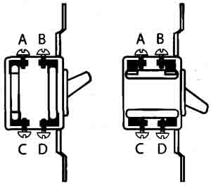
The wiring of three-way switches is simple, as these diagrams show. Run the white wire from SOURCE as usual to the light to be controlled. Run the black wire from SOURCE to the common or marked terminal of the first three-way switch. Run a black wire from the common or marked terminal of the second three-way switch to the light. That leaves two unused terminals on each switch; run two black wires from the terminals of the first switch to the two terminals of the second switch. It makes no difference whether you run a wire from B of the first switch to C of the second as shown, or from B of the first to B of the second. The wires that start at one switch and end at another are called runners, travelers, or jockey legs. Four-way switches : To control a light from more than two points, use two three-way switches, one nearest the SOURCE and the other nearest the light, and four-way switches at all remaining points in between. Four-way switches can be identified by the fact that they have four terminal screws and do not have ON-OFF markings on the handles. Figures 6-18 through 6-21 show two types of four-way switches and the wiring diagrams for circuits using each type. Depending on the manufacturer, the internal connections of four-way switches may be as shown in FIG. 6-18 or as in FIG. 6-20. In each of these figures, the four terminals are labeled A, B, C, and D.
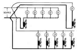
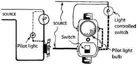
The four-way switch in FIG. 6-18 is shown in a circuit in FIG. 6-19. The two jockey legs from one three-way switch are connected to terminals A and B of the four- way switch; from the other three-way, the jockey legs are connected to terminals C and D of the four-way. The four-way switch in FIG. 6-20 is shown in a circuit in FIG. 6-21. The jockey legs from one three-way switch are connected to terminals A and D of the four-way switch, and the jockey legs from the other three-way are connected to terminals B and C of the four-way switch. If you are not sure which type of four-way switch you have, try one diagram; if it does not work, try the other. You can do no harm by wrong connections except that the circuit will not work if you have the wrong connection. Pilot lights : When a light can’t be seen from the switch that controls it, the light is often left on unnecessarily. The problem often occurs with basement and attic lights in homes and haymow lights in barns. Install a pilot light (a small, low-wattage lamp) near the switch so that both lights are turned on and off at the same time. The pilot light serves as a reminder that the unseen light is on. The wiring is shown in FIG. 6-22. First look at the diagram while disregarding the wires shown in dotted lines as well as the pilot light itself. It is then the same as FIG. 6-5. Add the wires shown in dotted lines and it becomes the same as the diagram of FIG. 6-7 except there are two lamps instead of five. The white wire runs to both lamps; the black wire from the SOURCE runs to the switch as usual; the black wire from the switch runs to both lamps, and the diagram is finished. A combination switch and pilot light in one device is shown in FIG. 6-23. The diagram is correct only for some brands; exact diagrams usually come with each device. There are also switches having a small pilot light in the handle. Some have a light that is on while the switch is in the OFF position to aid in finding the switch in the dark. Other diagrams and combinations : You will have little difficulty making a diagram for any desired combination of outlets and switches, whether single-pole or three-way, if you remember the principles covered in this section. To make any diagram, first locate each outlet where desired and run the white wire (light line like this) from SOURCE to every outlet. Then run a black wire (heavy line) from SOURCE to each outlet that is not controlled by a switch. Next run black wire (heavy broken line like this — — — —) from each outlet controlled by a switch to the switch that controls it. If three-way switches are involved, run additional black wires between the switches that control the outlet. Finally, from each switch run black wire (heavy line) back to SOURCE. Having done that, you may have to rearrange some of the wires to reduce the amount of wire used, but this will not affect the proper operation of the hook-up.
PREV: AC
Motors -- installation guide for home & farm Home • • |
Thursday, 2020-04-30 23:08 PST
