The simplest PV system configuration is a PV module or array connected directly to a DC load. Other components can be added to pro duce increasingly complex and sophisticated systems. A large number of combinations are possible for PV systems. The optimal con figuration for an application depends on load usage, load type, solar resource, auxiliary power sources, and many other factors.
Stand-Alone Systems
A stand-alone PV system is a type of PV system that operates autonomously and supplies power to electrical loads independently of the electric utility. Stand-alone PV systems are most popular for meeting small- to intermediate- size electrical loads, and are extensively used when other energy sources are cost-prohibitive or impossible. Stand-alone systems may be de signed to power DC and /or AC electrical loads, and typically store energy in batteries.
A stand-alone system may use a PV array as the only power source or may include one or more additional power sources, such as engine generators or wind turbines. However, most stand-alone systems do not interact with the utility grid.
Stand-alone PV systems are sized and designed to power a specific electrical load using the solar radiation resource at a given location. Since the size and cost of any stand alone system is related to the magnitude and duration of the electrical load and the solar resource, energy efficiency is critical. For these reasons, a thorough load analysis is the first step required in the design and installation of any stand-alone system.
Stand-alone PV systems are classified by their major components and the manner in which they operate in combination with other energy sources.
Direct-Coupled Systems. A direct-coupled PV system is a type of stand-alone system where the output of a PV module or array is directly connected to a DC load. These systems do not include any power conditioning equipment or electrical energy storage. The only other components are BOS components such as mounting systems and disconnects. ___4-15. Without batteries, direct-coupled systems are appropriate only when energy demand coincides with energy generation (when the sun is shining). Because PV output varies with irradiance, the load must also be capable of operating over a range of voltages.
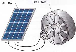
___ 4-15. Direct-Coupled Systems: The simplest type of PV system
is the direct-coupled system, consisting of only an array and a DC load.
DC motors are the most common loads for direct-coupled systems, including water pumps and ventilation fans. Direct-coupled PV systems are common for pumping potable and agricultural water supplies. In most of these applications, the water is either used as it is pumped or is stored in reservoirs or tanks. Direct-coupled ventilation fans provide airflow in proportion to irradiance, which is useful for applications such as attic ventilation. Circulation pumps for solar water-heating systems are also ideal applications of direct-coupled PV systems because the need to circulate hot water from a solar collector to a storage tank coincides with PV output. In this sense, direct-coupled PV circulation pumps provide inherent system control, eliminating the need for temperature controls to start and stop the circulation pump.
While direct-coupled systems are the simplest form of any PV system in terms of equipment, they are perhaps the most complex to design properly due to the lack of energy storage or system control. Matching the electrical load to the array is a critical part of designing a well-performing direct-coupled system. Because the output of the array changes with temperature and irradiance, the load does not always keep the array at its maximum power point. DC-DC converters or MPPT devices can be added to help better utilize the array power output.
Self-Regulated Systems. Most stand-alone PV systems require some type of energy storage, and batteries are the most common choice. Batteries are sized based on the expected magnitude and duration of electrical loads, and system operation characteristics. The PV array (and any auxiliary energy sources) must then be properly sized to fully charge the battery under the conditions of highest load and lowest solar insolation for the given application and site.
A self-regulating PV system is a type of stand-alone PV system that uses no active control systems to protect the battery, except through careful design and component sizing. It consists of only an array, battery, and load. Fewer components means a less expensive and more reliable system, but only if the system is properly designed. Otherwise, the system is vulnerable to overcharging or undercharging the battery. ___4-16.
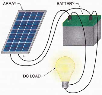
___ 4-16. Self-regulating systems avoid the complexity of adding
charge control components by precisely sizing the battery and array.
In order to prevent damaging the battery or charging it incompletely, the size of each component must be matched to the others. The magnitude and duration of the load must be known to a high degree of accuracy. The load must have a consistent load current and day-to day energy requirement or it must be controlled automatically. Consequently, these designs are not suitable for applications where the load is highly variable or externally controlled by a user or operator.
To protect the battery from overcharge, the battery system must be oversized in relation to the size of the array, which keeps charging current low. Specially designed modules also prevent overcharge by having a voltage range that closely matches the voltage of a fully charged battery.
Charge-Controlled Systems. If loads are variable or uncontrolled, charge control is required to prevent damage to the battery from overcharge or overdischarge. Charge control typically involves interrupting or limiting the charging current to a fully charged battery to prevent overcharge. Alternatively, the charging current can be diverted to a useful, but noncritical, auxiliary load to avoid wasting the excess power. ___4-17. Charge control is required by the NEC® if the array current is equal to 3% or more of the rated battery capacity in ampere-hours. For example, a 100 Ah battery would require charge control if the maximum array charging current exceeds 3 A.
==
Self-Regulating Navigational Aids
Perhaps the most successful application of a self-regulating PV system is the design of solar-powered marine navigational beacons. The electrical load is an incandescent lamp that has well-defined current draw and flash duration. The battery is large in relation to the size of the array and the load in order to meet energy requirements of the lamp under conditions of highest load (long winter nights) and lowest insolation (short winter days). Most importantly, low-voltage modules limit the charging current as the battery reaches full charge, preventing overcharge. The U.S. Coast Guard and other maritime authorities have deployed tens of thousands of these navigational aids on buoys and channel markers around U.S. coasts and inland waterways.
==
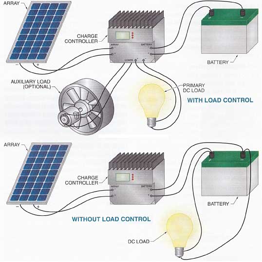
___ 4-17. Systems with charge control regulate the charging
current into the battery. Regulation may involve disconnecting or limiting
the array current or diverting the excess current into an auxiliary load.
Charge-Controlled Stand-Alone Systems: WITH / WITHOUT LOAD CONTROL
Stand-alone systems with battery storage also need to protect the batteries from overdischarge. Overdischarge protection typically involves disconnecting loads at a predetermined low voltage, corresponding to a low state of charge. Charge controllers may include this type of load control, or a separate load controller may be required.
When typical AC loads and appliances are used in stand-alone PV systems, an inverter converts DC power from the batteries to AC power at suitable voltage and power levels. However, the inverter adds system complexity and cost, and some power is lost in the con version process. Typically, the DC input for stand-alone inverters is connected directly to the battery bank, and the AC output is connected to a distribution panel to power the AC loads. DC loads may also be powered directly from the battery bank. ___4-18.
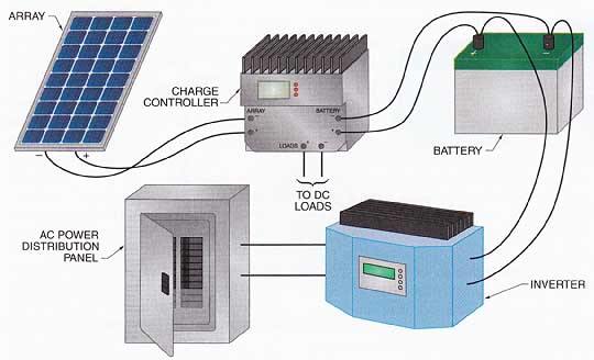
___ 4-18. Stand-alone systems for AC loads must include an
inverter, which draws DC power from the battery bank and changes it to AC
power for distribution. AC POWER DISTRIBUTION PANEL.
Utility-Interactive Systems
A utility-interactive system is a PV system that operates in parallel with and is connected to the electric utility grid. These systems are sometimes called “grid-connected” or simply “interactive” systems. These systems are the simplest and least-expensive PV systems that produce AC power because they require the fewest components and do not use batteries. The primary component in a utility-interactive system is the inverter, which directly interfaces to the array and the electric utility network and converts DC output from an array to AC power that is synchronous with the utility grid. ___4-19. Utility-interactive systems are modular, so large systems can be designed as multiple smaller systems with individual inverters, which are then connected together at a common utility connection.
Utility-interactive systems have a bi directional interface with the utility at the distribution panel. When the PV system does not produce enough power to meet system loads, additional power is imported from the utility. If there is an excess of PV power, the excess power is fed back (exported) to the grid.
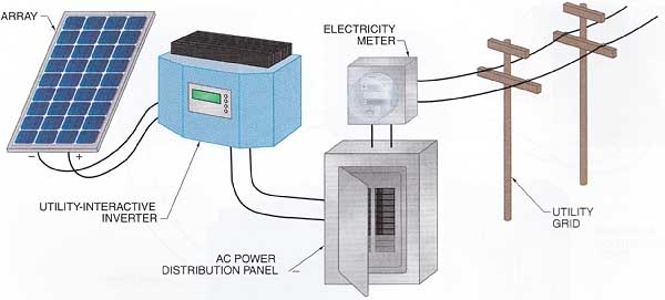
___ 4-19. A utility-interactive system is controlled by the
inverter, which adds AC power converted from DC power to the utility grid
power at the main AC power distribution panel.
Net Metering. If the PV system uses net metering, the utility’s electricity meter runs backwards when power is exported from the PV system to the utility. Net metering is a metering arrangement where any excess energy exported to the utility is subtracted from the amount of energy imported from it. ___4-20. Using this system, energy supplied to the utility from a PV system is effectively credited to the customer at full retail value.
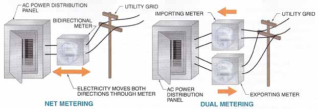
___ 4-20. Utility-interactive systems have either net-metering
or dual-metering arrangements for exporting electricity to the utility grid.
Customers are usually not paid for net excess generation, but credit may be carried over from month to month. This works out very well for systems that produce excess power during the high-insolation summer months but require supplemental power from the utility during the low-insolation winter months. If the PV system and loads are perfectly balanced for annual energy production and demand, the result is a net energy bill of zero. However, some net metering energy credits expire after a certain period, typically one year. Net metering arrangements are not available for all PV systems or with all utilities, but they are becoming increasingly common.
Dual Metering. Some large interactive distributed generation systems are not net metered, but dual metered. Dual metering is the arrangement that measures energy exported to and imported from the utility grid separately. This arrangement allows energy delivered to the consumer to be billed at full retail value, while power delivered to the utility is credited at a lower wholesale value, the cost the utility pays to generate or purchase energy.
Islanding. If the utility experiences an outage, utility-interactive inverters must stop supplying power to the grid. This is because an inverter exporting power to the utility lines is a serious electrocution hazard to any line workers that may be working to restore power. Interactive inverters monitor utility grid conditions and suspend power exporting when the utility power falls out of the normal range in volt age or frequency. Islanding is the undesirable condition where a distributed-generation power source, such as a PV system, continues to transfer power to the utility grid during a utility outage. Anti-islanding provisions are required for all listed interactive inverters.
Interconnection Agreements. Permission is required to interconnect PV systems with the utility grid, since the power affects the utility’s distribution system. Risks to the utility include poor power quality from the inverter affecting other consumers on the grid and safety concerns for their electricians about islanding. It is the jurisdiction of the local utility to determine specific interconnection requirements, though general provisions are often established by the state. Most utilities have simple interconnection agreements for PV systems up to a certain size, which require little more than that the system be inspected by local officials for code compliance. Other possible provisions include special labeling, external disconnects, insurance, metering, and billing arrangements.
Bimodal Systems
A bimodal system is a PV system that can operate in either utility-interactive or stand-alone mode, and uses battery storage. Bimodal systems are sometimes referred to as battery-based interactive systems. The key component in a bimodal system is the inverter, which draws DC power from the battery system instead of the array. In this case, the array simply acts as a charging source for the battery system.
Bimodal systems operate in a manner similar to UPSs and have many similar components. Under normal circumstances, bimodal systems operate in interactive mode, serving the on-site loads or sending excess power to the utility grid while keeping the battery fully charged. However, if the grid becomes de-energized, a transfer switch automatically disconnects from the utility and operates the inverter to supply AC power sourced from the battery bank. ___4-21.
If the system must be taken off-line for ser vice or maintenance, a manual transfer switch or bypass circuit can isolate the array, battery, and inverter from the remainder of the system and directly connect the loads to the utility supply.
Bimodal systems are typically used to back up critical loads, but can also be used to man age the energy supply for different times of the day in order to reduce electricity bills.
Critical Load Backup. Bimodal systems are extremely popular for homeowners and small businesses where a back-up power supply is required for critical loads such as computers, refrigerators, water pumps, or lighting when a utility power outage occurs. In this configuration, the AC power from the inverter is routed to an isolated subpanel that serves only the critical loads.
The ability of these systems to provide back-up power is a significant advantage over interactive-only systems, despite the extra costs (primarily for the battery bank). However, when in back-up mode, the array output and battery system capacity are still limiting factors. As with stand-alone systems, careful sizing and load management are essential for the bimodal system to adequately supply the critical loads for the required amount of time.
Utility Rate Management. Some utilities use time-of-use rates to charge more for electricity during peak demand times of the day than during off-peak times. Peak hours are typically during the day when people are using household appliances and businesses are open. Electricity demand is relatively low during the night. If the rates are significantly different, a bimodal system can be used to manage utility energy use for optimal electricity rates.
A bimodal inverter can be programmed to supply the loads with energy from the array and battery bank during peak times, avoiding or minimizing the use of high-priced utility electricity. During off-peak times, the loads can be powered and the battery bank charged with less-expensive utility electricity. Since peak utility rates are typically charged during the middle of the day when insolation is at maximum, any excess PV energy can be sold back to the utility at higher peak retail rates (if the system uses net metering). This type of system can still function as a backup to the electric utility during an outage, though the use of the battery bank must be carefully controlled to leave capacity available for back-up use.
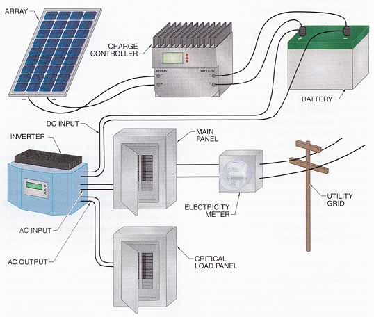
___ 4-21. Bimodal systems can operate as either
a utility-interactive or a stand-alone system. CRITICAL LOAD PANEL; UTILITY
GRID; DC INPUT; AC OUTPUT; ELECTRICITY METER
==
Combined Heat and Power Systems
Most large-scale central power plants burn fuel to drive the generating process, but convert only about one-third of the energy content in the fuel to electrical energy. Most of the remainder is wasted as heat and is dumped, unutilized, into the atmosphere or waterways.
However, distributed generation applications can sometimes use combined heat and power (CHP) technology (also called cogeneration) because they are located near the electrical and thermal loads. Waste heat from power generation is recovered and used for water, space, and process heat applications. CHP systems save fuel that would otherwise be used to produce heat or steam in a separate unit, improving fuel utilization efficiencies to 70% to 90%. Although many types of distributed generators, such as internal combustion engines, rely on nonrenewable fossil fuels, utilizing the fuel more efficiently with CHP applications greatly improves their value.
Small-scale, or micro-CHP, systems for residences and commercial buildings are available but still relatively rare. These systems primarily use internal combustion engines, though new systems based on microturbines or fuel cells are expected to increase the popularity of CHP technology. Solar energy can also be considered a CHP application by using solar thermal systems along with PV systems.
==
Case Study:
IBEW Local 103 Training School
Location: Dorchester, MA (42.3°N, 71.1 °W)
Type of System: Utility-interactive hybrid
Peak Array Power: 5.3 kW DC
Date of Installation: December 2002
Installers: Apprentices and journeymen
Purposes: Training, community awareness, supplemental electrical power
As IBEW Local 103 in the Boston area has learned, PV and wind power complement each other quite well. Being located next to a busy expressway, the Local took the opportunity to showcase its members’ technical expertise by installing first a PV system, and later a wind turbine, on its property.
The PV array is mounted on the curtain wall surrounding the air conditioning equipment on the roof of the building. The vertical orientation is not optimal for electricity production, but offers other advantages. The wall is an established surface (requiring little additional mounting structure) that is readily accessible and is easily visible from the ground and the nearby expressway. Since a primary reason for installing the system was to increase public awareness of renewable energy technologies, the array location is ideal. The air conditioning enclosure also protects the junction boxes, disconnects, and inverters. The resulting AC power is routed into the main service panel inside the building.
In May 2005, Local 103 completed installation of the first wind turbine in the city of Boston. The wind turbine stands over 114’ tall, with three 34’-long blades, and has a rated power output of 100 kW. The generator windings are excited by utility voltage, so the three-phase AC power output is automatically synchronized to utility power. The AC power is then routed to the main electrical service of the building. Since the output from the PV system and the wind turbine combine only at the AC power side at the building’s main electrical service, this is an AC bus system.
Data from the main controller of the wind turbine is also routed into the building, where it is monitored and displayed. Statistics from the turbine are available on Local 103’s web site.
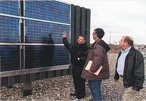
A representative from Local 103 explains to electrical inspectors
how the PV modules generate electricity and contribute to meeting the
electrical demand of the building.
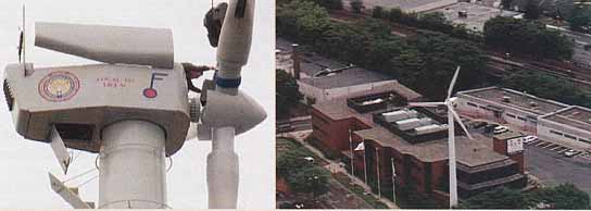
A Local 103 member assists in aligning the three 34’-long turbine
blades on the generator section of the wind turbine. (right) In addition
to meeting a portion of the electrical demand of the building, the PV
system and wind turbine showcase the Local’s progressive outlook on alternative
energy to the community.
==
Hybrid Systems
A hybrid system is a stand-alone system that includes two or more distributed energy sources. (Utility-interactive systems may also use multiple distributed energy sources, al though these are not strictly defined as hybrid systems.) Common energy sources used in hybrid systems include PV arrays, engine generators, wind turbines, and micro-hydro electric turbines. ___4-22. Hybrid systems offer several advantages over PV-only or generator-only systems, including greater system reliability and flexibility in meeting variable loads.
Using a variety of energy sources may also reduce the total system costs. For example, PV-only stand-alone systems are generally cost effective for smaller loads, while engine generator-only systems are usually cost effective for larger loads. In between, at about 20 kWh/day to 100 kWh/day, a hybrid PV system can have a lower initial cost than a PV only system and a lower life cycle cost than a generator-only system.
Hybrid systems are perhaps the most complex of all PV systems in terms of equipment, system design, and installation. However, they offer the greatest flexibility with regard to configurations and control strategies. The contribution from each source can be optimized for the application while minimizing the initial and operating cost. For example, an array may be designed to power the loads only during the months with the highest insolation, with an engine generator supplying the balance of energy required at other times. The engine generator can be loaded to its maximum output for meeting system loads and charging a battery bank, thereby increasing its fuel efficiency. Also, PV arrays and battery banks can be down-sized in hybrid systems because auxiliary energy sources provide additional power.
Hybrid systems are classified by the way in which the power outputs from the various sources are integrated. A DC bus hybrid system is a hybrid system that combines DC power output from all energy sources, including the PV array, for charging the battery bank. The sources are either all DC or rectified to DC before integration. For example, a common DC bus hybrid system integrates a PV array with a small wind turbine.
In some circumstances, AC power sources can instead be integrated on the AC side if they can be configured for synchronized output. An AC bus hybrid system is a hybrid system that supplies loads with AC power from multiple energy sources. For example, some inverters can match the frequency of the output from an engine generator so that the two power sources will be compatible.
Many modem inverters are specifically de signed to integrate and control multiple energy sources by including built-in battery chargers and automatic transfer switches. For example, when a battery bank is discharged, the inverter control relays may start an engine generator and automatically transfer the loads to the output from the generator. The array power is then used to charge the battery bank.
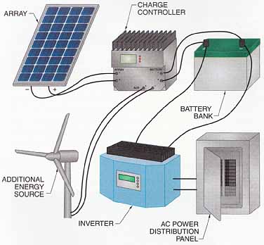
___ 4-22. Hybrid systems include power sources other than the
PV array and do not interact with the utility grid.
Next: Unit Summary, Definitions, Quiz / Answers