AMAZON multi-meters discounts AMAZON oscilloscope discounts
The Devil is in the Details
"The devil is in the details" is an adage applicable to machinery maintenance. It means that reliability requires close attention to key machine details, such as design, assembly, installation, and maintenance. But, if the operation of equipment is not right, these other items cannot improve reliability. For example, a pipe hanger located 20 or 30 feet from a pump that is not functioning properly can have a significant effect on pump nozzle loads. Consequently, if the pipe hanger fails or malfunctions further, pump failure can soon follow. While a pipe hanger may not seem to be machinery or operations related, a failed pipe hanger should be considered a critical component failure in the pump-foundation-piping-control system. If detected early, the problem can be corrected.
If you want to set yourself apart from the others in your group, learn all you can about machinery and machinery systems. A simple change in perspective can have a major impact on how you view and understand your machinery. By widening your view of machines and thinking about them in terms of integrated systems, you can begin to understand how critical internal and external components must interact with one another to provide a reliable system. Operators play an important role in ensuring the ongoing reliability of rotating equipment by closely monitoring them with a trained eye. They can detect problem that if addressed quickly can mitigate or eliminate future problems.
In this SECTION, you will find valuable insights about key machine components, such as anchor bolts, pipe hangers, couplings and how they can affect the overall reliability of machines. Also covered is the importance of knowing the machinery design and operating details when troubleshooting process machines.
Anchor Bolt Inspections
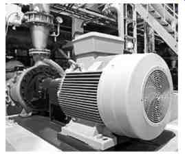
FIG. 1-Centrifugal Pump and Motor Attached to Concrete Foundations with
Anchor Bolts
Anchor bolts play a vital role in the restraint, support, and alignment of process machinery. Broken or loose anchor bolts will lead to excessive vibration or allow machine-to-driver misalignment.
Here are some proven tips for maintaining the effectiveness of anchor bolts:
• Anchor bolts must be tight. Look for indications of looseness such as liquid being pushed in and out from under the bolt, washer, or frame of the equipment. Occasionally try to turn anchor bolt nuts by hand or with a tool to see if they are tight.
• Tap on the anchor bolt to listen for a dead sound that might indicate a broken bolt. See if the nut and anchor in the foundation move. If pliers are used to test tightness, a slight pull upwards on the bolt or stud will help to indicate if it is anchored or has come loose.
Looking Up
How often do you look upward while walking through your plant? Do you ever inspect the pipe, pipe supports, spring cans, bolting, insulation, and so on? This inspection technique is a must for safety and equipment reliability. I remember seeing a nut on the floor of a plant and looked up to see that it came from a 4 bolt flange. The flange had only 3 bolts and was labeled "Sulfuric Acid." Consider how many times a day someone walked under the potentially leaky flange.
Unmaintained supports are one of the largest, if not the largest, contributors of maintenance issues we see today. (Figures 2 through 4 are examples of unmaintained piping supports.) Failed pipe supports lead to high nozzle loads, which put added loads on bearings and seals and eventually cause premature equipment failures. Furthermore, when equipment bases are loosened due to piping strain, often the base is repaired without a resolution of the true cause of the problem. Unresolved piping strain will continue to shorten the life of the grout, causing base looseness and related misalignment issues.
Pipe supports in hot service and around steam turbines are particularly important. Failure in any way of these supports or slides that allow controlled movement can result in premature equipment failure.
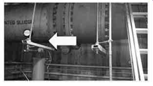
FIG. 2-Notice that one valve support is not contacting pipe
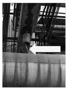
FIG. 3-Hanger support is broken
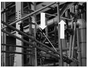
FIG. 4-A rope support has slipped and cocked the pipe
Coupling Inspections
When passing by machines that are coupled, look for parts on the ground that may have come from a separating coupling. Items may include broken shims from a shim-pack coupling. You should also look for the dust that is created by the degradation or severe misalignment on couplings with a nonmetallic coupling spacer. A strobe light can be used to inspect the coupling while the machine is running, provided the coupling guard allows it. Operators should always ensure that maintenance crews clean up after their work, so that any new material found on the pedestal, equipment base or around the machine is from the installed coupling.
Know your Equipment
Know your equipment. Have you heard complaints that a pump is not producing enough flow or pressure or that a gear box is running too hot? The first question we need to answer is: What was the flow, pressure, or temperature yesterday or last week when there was no problem? Only operators can answer those types of questions. Key operating conditions should be recorded after starting any piece of critical equipment and should be taken and recorded on a regular basis.
It is also important to know the basic construction of your equipment. FIG. 5 is an example of a gear box schematic that may help troubleshoot when a problem is detected.
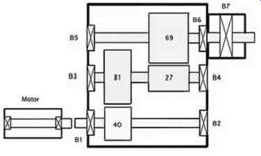
FIG. 5-Gearbox Field Sketch
Always note current ambient temperature when evaluating equipment temperature readings. If the ambient temperature is substantially higher or lower than when the readings were first recorded, it may be necessary to take that factor into account when looking at the current value. Looking for obvious changes in any of the operating conditions is a simple, yet effective method of field troubleshooting.
Remember that capturing actual field data with an accurate instrument is invaluable when troubleshooting. If someone thinks the gear box is hot because it's running 160°F when it was running 150°F at startup, you have data to prove whether it is or isn't. It is more helpful to have objective values, such as a bearing housing reading of 150-degree F, than to have subjective information such as "hot to the touch." Your senses are a good indicator to know when it is necessary to use an objective measuring tool.
Walk-Through Secrets: What to Look For On Your Regular Inspections Rounds
Walking through a plant and looking at the equipment can be an eye-opening experience, because there are many opportunities in the plant to prevent catastrophic damage to equipment. Failure detection and prevention starts with knowing what "normal" is for your equipment. Many small issues can be fixed or corrected that will eliminate large safety, environmental, and costs in the near future.
Remember, there are many abnormal conditions or problems that operators see that no one else does.
In addition, the operator is the only one that knows what normal sounds like, looks like, or feels like.
For example it is usually not good to see foam in the lubricating oil. If, as the operator, you saw foaming yesterday, last week, last year and for the past five years and the equipment has had no repairs during this time then the presence of foaming in this machine, in this process, in your plant is likely not a problem. Only an alert operator would know this type of equipment-specific information and could use this valuable resource should a problem arise on this piece of equipment.
FIG. 6 shows two oil bowls, one for the turbine and one for the pump. What should catch your attention is that the two oil colors are very different. If, as an operator, you do not understand why this is happening, this condition should be brought to someone's attention. Is the dark color on the turbine because the oil has become too hot and oxidized? Is the oil on the pump freshly changed? Are the two oils simply different? Perhaps, the oil in the pump appears light when new and the turbine oil appears darker when it is fresh. These are just a few lubrication observations to consider when making the rounds through the plant.
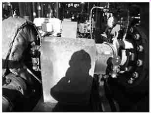
FIG. 6- Oil bowls on a centrifugal pump with turbine driver
The equipment in FIG. 7 has several problems, all of which should catch your attention. The first problem is that the seal is missing a bolt, which should be a big concern. Another issue is that the pressure gauge is rusty, has no gauge glass, and is pegged on the zero stop.
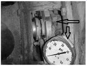
FIG. 7-Pump with several problems
The mechanical seal in FIG. 8 is installed on a boiler feed pump. This should be an API (American Petroleum Institute) seal flush plan 21 that is composed of a heat exchanger on the stuffing box flow to cool the water entering the seal area. If the exchanger is not working, the additional heat generated by the seal can cause flashing or boiling on the seal faces which will be the same as the seal running dry. The operator should check the exchanger by detecting a differential temperature to and from the seal as well as inlet and outlet water of the exchanger. This can be done with tools or by touch. Precautions should be taken to ensure you are not burned.
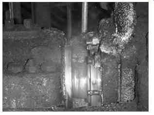
FIG. 8-Seal in a boiler feed pump
Mechanical seals require start-up attention and often go unchecked. Inspection at start-up is imperative to ensuring the necessary flush rates are applied if applicable.
The expansion joint shown in FIG. 9 is obviously over-compressed. This is a catastrophic release waiting to happen. Some expansion joints have "stay rods" (see the expansion joint with stay rods in FIG. 10) that must be connected. Stay rods limit the amount of expansion that can take place and prevent the expansion joint from blowing up like a balloon and pulling apart.
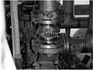
FIG. 9-Over-compressed expansion joint
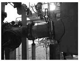
FIG. 10 Expansion joint loose stay rods
Take the time to inspect pumps, piping, supports, lubrication, and all associated equipment at your plant.
One new technology that can be used to look at your running equipment and flow process piping is the infrared camera, which uses a technique known as thermography. The camera shows heat differences inside piping and equipment that can indicate restrictions, hot spots, and other problems. Infrared cameras can be used on motors, pumps, turbines, fans, bearings, compressor valves, and more as a new way of predicting failures. The first indication of a machinery problem can often pay for the cost of the camera many times over if a failure is averted.
The thermograph in FIG. 11 shows that the lip seal in an ANSI pump is running about 100 degrees hotter than any other part of the pump. This is why so many smart maintenance groups have followed the API and ANSI recommendations that labyrinth seals, not lip seals, be used on bearing housings. The higher the speed, the hotter the lip seal operates when it is newly installed; then as the seal wears, the heat is reduced, and the seal's ability to seal is lost.
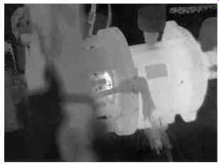
FIG. 11-Thermograph showing a hot lip seal
FIG. 12 shows a centrifugal pump casing foot with a loose bolt. The bolt is not doing its job of securing the pump case to the baseplate and maintaining its alignment. Whether the bolt is a little loose or very loose, the effect on alignment is the same. One condition is just more obvious than the other. When you find these types of problems, document the information so it can be used in a Root Cause Failure Analysis (RCFA) if required. In many instances, loose hold-down bolts go undetected or undocumented and cause mechanical seal or bearing failures. And when the equipment ultimately fails, the seal or bearing will likely be wrongly blamed allowing the potential for the problem to reoccur.
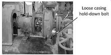
FIG. 12-Loose foot bolt on a centrifugal pump casing
The pump in FIG. 13 is equipped with a bull's-eye sight glass that has been sand or bead blasted and now it's useless.
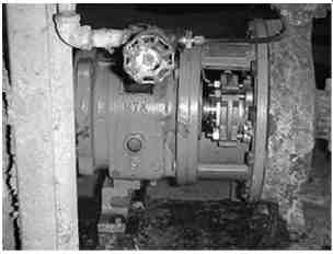
FIG. 13-Damaged bull's eye sight glass
If there is a clear plastic drain installed on your equipment as in FIG. 14 watch it closely. With this type of trap in place, you can easily see water in the bottom of the pump housing you can detect wear particles and oil color changes and bleed off any water contamination once detected.
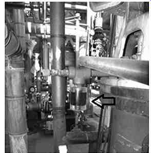
FIG. 14- Oil sight on sump
FIG. 15 shows a pipe shoe that does not contact the pipe's support, which causes pipe strain, a condition where piping attached to machines induces unacceptably high stress into the machine frame and support system. The worst case would occur if the pipe shoe moved so far that it hooked over the support and could no longer move at all.
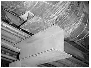
FIG. 15-Pipe shoe not contacting pipe support
Summary:
This SECTION can be summarize by stating that to maximize the reliability of your rotating equipment you should 1) know your machines, 2) follow your machine-specific procedures, 3) be vigilant of changes, and 4) perform regular walk-throughs or rounds. The observations and data recorded during your regular rounds will be invaluable if a root cause failure analysis is ever performed on one of your failed rotating equipment. No machine detail or observation is too insignificant when it comes to equipment safety or health.
Quiz
1. Occasionally try to turn nuts by hand or with a tool to insure they are tight.
2. Failure detection and prevention starts with knowing what is for your equipment.
3. List four ways to maximize the reliability of your rotating equipment.
4. List 2 items that are external to your machine that, when not installed properly or maintained, can reduce the life of your equipment.
5. List at least two things to look for during a coupling inspection.
6. If supervision does not act on your findings, should you stop telling them of problems you have found?
Answers
1. Occasionally try to turn anchor bolt nuts by hand or with a tool to insure they are tight.
2. Failure detection and prevention starts with knowing what "normal" is for your equipment.
3. List four ways to maximize the reliability of your rotating equipment.
• Know your machines.
• Follow your machine-specific procedures.
• Be vigilant of changes.
• Perform regular walk-throughs or rounds.
4. List 2 items that are external to your machine that, when not installed properly or maintained, can reduce the life of your equipment.
• Pipe supports
• Flex legs
• Pipe expansion joints
• Expansion slides
5. List at least two things to look for during a coupling inspection.
• Coupling dust on the baseplate from a flexible coupling
• Broken coupling spacer shims
• Broken coupling bolts
• Coupling keys
• New dents in the coupling guard.
6. If supervision does not act on your findings, should you stop telling them of problems you have found? No, you should not stop telling supervision about problems you have found. It is the only way your observations can ever be acted on.
Prev. | Next
Home top
of page Guide index