AMAZON multi-meters discounts AMAZON oscilloscope discounts
1. Fastening types
In nuclear power plants and other nuclear installations, a basic distinction is made between safety-related and non-safety-related fastenings. Safety-related fastenings are those used to attach safety-related structural and system components. In nuclear power plants, safety-related structural and system components are those required to meet safety goals (controlling reactivity, cooling fuel elements and containing the radio active materials) and to limit radiation exposure as part of incident management.
Important safety-related fastenings performed using anchors also include those to which structural and system components are attached which are not safety-related in themselves, but which could cause unacceptable effects on safety-related structural and system components in case of their failure.
Today, that means that the fastenings used in nuclear power plants and other nuclear installations are overwhelmingly safety-related ones. These fastenings can be divided into cast-in fastenings and subsequently mounted (or post-mounted) fastenings.
1.1 Cast-in fastenings
The best-known and most used cast-in fastenings are anchor plates of steel to which system components are welded. Where fastening points are already known at the construction stage, the anchor plates used are mainly headed stud anchorings which are built in along with the reinforcement, before pouring concrete (Figure 1).
Headed stud anchorings have a general approval issued by the German Institute for Construction Technology (in German; Deutsches Institut fur Bautechnik - DIBt), for general building construction, but not for accidental actions such as earthquakes.
Cast-in fastenings must be planned precisely before construction starts, defining the load to be absorbed and where the fastening points are to be positioned.
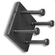
Fig. 1 Anchor plate with headed stud anchorings (source: www.halfen.de)
1.2 Post-mounted fastenings
Post-mounted fastenings are used to transmit loads wherever detail design has not provided for any cast-in fastening points before construction has started or where new fastenings become necessary in the course of refitting work. However, there are also design challenges here: although loads, dimensions and positions of system components are known precisely, high density of reinforcement, poor access and closeness to other fastening points or structural section edges may make planning, designing and installing fastening points extremely complex. The options available for post-mounted fastenings are basically as follows:
- run-through anchors
- spreading anchors
- undercut anchors
- composite anchors
- cast-in anchors
For safety-related fastenings, only fastenings with sufficient mechanical grip should be used. With metallic anchors, this can be achieved very well by using form-locking undercut anchors, so that a general authoritative approval only exists for undercut anchors, although work is underway to achieve an approval for composite anchors in the near future.
1.3 Load-bearing capacity
The load-bearing capacity of fastenings in concrete sufficiently far from edges of structural components can be divided into modes of failure as follows.
- tension failure:
- steel failure
- extrusion
- concrete cone failure
- gaps
- transverse tension failure
- steel failure
- concrete pry-out
- concrete edge fracture.
The design principles can be found in the following bodies of rules:
- ETAG 001(Guideline for European Technical Approval)
- CEN/TS (Comite Europeen de Normalisation/Specification Technique)
- Guidelines on assessing anchors fastenings to be used in nuclear power plants and other nuclear installations DIBt,
- Guidelines for anchor fastenings in nuclear power plants and other nuclear installations, DIBt, June 2010.
2. Fastening with headed studs
2.1 History
The use of headed studs in fastening systems dates back to the early 1970s. The first headed studs used in building nuclear power plants were PECO concrete anchors. In 1971, Peco Bolzenschwei_technik GmbH was acquired by Nelson StudWelding Co. and had its name changed to Nelson Bolzenschweiss-Technik GmbH. After a long time as part of the TRW-group, Nelson Bolzenschweiss-Technik moved to the Fabri-Steel Group in Michigan, USA, in 2000, and has belonged to Doncasters Group Ltd, UK, since 2009. However, the company label, Nelson, remains unchanged to date.
The headed studs found in older nuclear power plants under the names 'Peco', 'Nelson' and 'TRW-Nelson' are all the same product. Following extensive tests and expert opinions by Professors Roik and Bode, the DIBt granted the first general approval for headed studs (anchoring steel plates using welded-on Nelson headed studs, approval no. Z-21.5-82) in 1983.
Not long after that, the DIBt issued further headed stud licenses for the Koster & Co. of Ennepetal (Z-21.5-280) and Riss AG of Dallikon, Switzerland (Z-21.5-296).
Headed stud anchors were still designed based on permissible tension and lateral loads at the time. Existing edge and plane factors were allowed for via reduction factors (kappa method). When the license was amended in 1995, an extended calculation method (CC method) was introduced and the semi-probabilistic safety concept was used instead.
The DIBt issued the first European Technical Approval for fastenings in November 2003. The two license notices ETA-03/0039 (KOCO headed studs) and ETA-03/0041 (Nelson headed studs) were extended in 2008, and are the current state-of-the-art rules.
The particular safety requirements involved that mean using headed studs in nuclear power plants must be approved by the licensing authorities in each case.
2.2 Usage and characteristics
Anchor plates with headed studs are found in power plants, in both safety-related and non-safety-related applications. They are used for example as supporting and load transmission points for platforms as well as for mounting devices for pipe and cable racks, risers etc. Figure 2 shows a schematic anchor plate with headed studs.
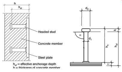
Fig. 2 Fastening an anchor plate, schematic
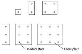
Fig. 3 Possible arrangements of headed stud anchors
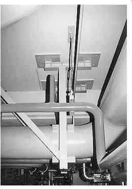
Fig. 4 Typical anchor plates fixed in a power plant
Anchor plates vary in size from small two-bolt units to groups with nine headed studs;
there are even larger sizes, though, such as 4x4 or 5x5 headed studs up to 2.0m long anchor strips with up to 25 headed studs. Larger anchor plates often need additional reinforcement to back-anchoring of tensile forces.
Large anchor plates can be used for a great variety of connection arrangements, but their load transmission is always limited to a local area.
In former times headed stud diameters ranged from 3/800 (9.52mm) to 7/800 (22.22mm) with a ratio of head to shaft diameter of between 1.60 and 2.0. Headed studs 175mm long were preferred: if a greater anchoring length was required, or if it was wished to anchor the headed studs within the background bending compression area, two or even three headed studs would be welded together. This method can still be used today, but it should be noted that, for the extended anchor length to be effective, cushion rings must be fitted at all bolt heads except the final one welded on.
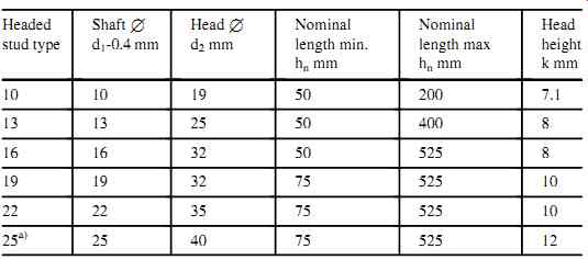
Table 1 Headed stud types to ETA-03/0041
Headed studs were then made in accordance with DIN 17100 of structural steel St37 3K with a minimum tensile strength of 450N/mm^2. Stainless steel was used in areas where increased corrosion protection was required for plates (1.4571, 1.4401) and headed studs (1.4301, 1.4303). At the time when German nuclear power plants were built, stainless steel bolts were only available up to 16mm diameter.
For new construction projects, headed studs are available in any length from 50mm to 525mm today. Beyond the standard range, special lengths are even available for special applications up to 750mm, including the welding tools required. The characteristics of the material properties remain unchanged. Under the amended standards, the material designation for the unalloyed bolt steel. The material code for alloy steel is unchanged.
Bolt diameters were changed nominally to the metric system, with a new size being added of 25mm. Stainless bolt heads are currently available in sizes from 10 to 22mm, and there are plans to add 25mm diameter bolts to the stainless range also (Table 1).
Headed studs are now designated SD for short, and are governed by DIN EN ISO 13918 (formerly DIN32500-3:1979).As for bolt materials, there is a cross-reference to standard ISO/TR 15608. Under this, material properties are subdivided into groups SD1, SD2 and SD3. The bolt material prescribed under ETA approval is equivalent to group SD1,with a minimum tensile strength of 450N/mm^2 . Group SD2 covers materials with a reduced tensile strength of 400N/mm^2 and a yield point of 235N/mm^2 . The approvals do not cover group SD2 materials for applications in anchor plates.
Material group SD3 covers stainless steel materials (1.4301, 1.4303) with a yield point of not less than 500N/mm^2.
For all three of these groups, the carbon content is limited to 0.20% and they must contain at least 0.02% of relaxing elements.
2.3 Load-bearing behavior of headed studs
Headed stud fastenings are relatively rigid anchor constructions. The welding of headed studs to steel plates and then concreting those steel plates into reinforced concrete components gives a direct interlocking between steel and concrete. Due to forced spreading, the anchor area will not be affected by drilling or splitting forces. Headed studs show a ductile load-bearing behavior and good deformability at the ultimate limit state.
The structural strength of headed studs depends on many factors, primarily the strength characteristics of the steel and the compressive strength class of concrete. Geometric factors such as diameter and length of the headed studs and distances from free component edges or adjacent anchorings exhibit a major influence, too.
Potential failure modes of anchorings with welded on headed studs as a function of the type of stress are shown in Figure 5.
2.4 Standards and approvals
The rules to be observed when using anchor plates with headed studs are as follows:
- European Technical Approval for steel plates with cast-in headed studs for the manufacturer in question, e.g. ETA 03/0041 for Nelson headed studs
- ETAG 001, Guidelines for European Technical Approval of metal anchors for use in concrete, Annexe C, Design methods for anchorages, February 2008,
- DINENISO13918:2008,Welding - Studs and ceramic ferrules for arc stud welding
- DIN EN 14555:2006, Welding - Arc stud welding of metallic materials
- DIN EN 10025-1:2005, Hot-rolled products of structural steels - Part 1: General technical delivery conditions
Fig. 5 Potential failure modes of headed studs
- DIN EN 10088-1:2005, Stainless steels - Part 1: List of stainless steels
- Deutsches Institut fur Bautechnik, using anchors in nuclear power plants and nuclear installations, guidelines for assessing anchor fastenings when granting approvals in individual cases under German Federal States Building Regulations 1998:09
- Deutsches Institut fur Bautechnik, Guidelines for anchor fastenings in nuclear power plants and other nuclear installations, June 2010
- DIN SPEC 1021-4-2:2009, Designing anchoring of fastenings for use in concrete - Part 4.2: Headed studs, German version CEN/TS1992-4-2:2009.
2.5 Planning and design
2.5.1 Basics
During the construction period of the first nuclear power plants no general authoritative approvals for headed studs had existed. Anchorings were designed and built based on consent orders from the building authorities concerned. These orders and their associated expert opinions governed the permissible combinations of stresses for tension and shear loads for headed studs and covered any boundary or group influences individually.
When designing anchor plates, a distinction is made between safety-related and non safety-related units.
The design and construction of fastenings for non-safety-related components is based today on the general technical approval (ETA) for the significant combination of characteristic loads concerned.
Beyond the provisions of the General Technical Approvals, safety-related components are subject to additional requirements in terms of the structural load-bearing and deformation behavior of the anchorings.
As well as for the effects of actions from characteristic loads, safety-related anchorings with headed studs must also be designed to withstand the effects of actions from accidental external events such as earthquakes or for internal anomalies. Designing anchorings for special load cases also includes the effects of impulsive actions and the occurrence of cracking in reinforced concrete structure with wide cracks.
The design of anchor plates within headed studs for attaching safety-related components is not covered by General Technical Approvals; nor has any such General Technical Approval for accidental actions (K-approval) yet been applied for at the Deutsches Institut fur Bautechnik. That means using anchor plates for safety-related components is still subject to approval by the supreme building authority in each case.
This involves verifying structural strength and serviceability of anchor plates in accordance with DIBt Guidelines. Finally, the suitability of the anchoring for the specific intended purpose in nuclear power plants must then be assessed by an expert opinion.
2.5.2 Verification of load-bearing capacity and serviceability
It is a general rule for all structural fastenings that they must be designed by engineers.
Deciding how to design them at the execution stage is not enough. So anchor plates with headed studs must be designed in an engineering-like manner also. This includes providing analytical verification that they have sufficient structural strength and serviceability and producing detailed drawings concerned, such as anchoring and formwork drawings.
Within the scope of general engineering construction and for non-safety-related anchorings, verification of the load-bearing capacity is based on the General Technical Approvals. Such approvals contain all the details required of specific product strengths, permitted edge and centerline distances and instructions and cross-references to the calculation methods to be used.
According to the current status of the General Technical Approvals, anchor plates with headed studs are designed in the same way as anchors based on Annexe C to European Guidelines ETAG 001. Design includes verification of headed studs against steel failure and verification of the anchor base against concrete failure. In terms of concrete failure, there are a number of failure modes to be considered, depending on the effects of actions involved, such as concrete cone failure, concrete edge fracturing and pry-out failure. The individual failure modes and calculation procedures are described in detail.
In addition to the provisions of ETAG 001, General Technical Approvals for anchor plates with headed studs include additional reinforcement for anchoring the headed studs within the background bending compression area. Particularly where anchorings are close to edges, in new buildings, specifying such additional reinforcement can avoid broken edges and improve structural strength. Further studies on the effectiveness of back-tying reinforcement are described.
During the construction period of the first nuclear power plants there were not yet any rules on using back-tying reinforcement for anchorings with headed studs. For post calculating anchor plates as part of repairs and retrofits, more recent rules in DIN SPEC 1021-4-2:2009 govern the co-function of existing structural component reinforcement. The existing reinforcement must meet certain design principles such as a sufficient anchoring length inside and outside the fracture cone and should be in the influence area up to 0.75 hef by the headed studs. If these conditions for use are satisfied, anchorings close to edges in existing structures can often be shown to have a greater structural strength. The more extensive rules in DIN SPEC 1021-4-2:2009 are expected to be incorporated in individual approvals for headed studs by the end of 2010.
General Technical Approvals do not cover the verification of the structural strength of anchorings for safety-related components; this must therefore be approved on a case by-case basis.
The notice of consent given by the authorities concerned and the associated expert opinion lay down the calculation methods to be used and the rules to be followed. In exceptional cases, they also include details of the materials to be used, the number and size of the studs to be used for the anchor groups concerned and additional provisions on partial safety factors, if required.
One essential feature here is the data on the structural strength of headed studs in cracked reinforced concrete structural components under accidental actions. This data is based on additional tests and assessments in line with DIBt Guidelines, and provides the design basis for fastenings in requirement category A3 to DIN 25449:2008.
The notice of approval also contains additional general rules on accounting for existing reinforcement.
The serviceability of anchor plates with headed studs is less important with non-safety related fastenings. The loads to be induced are generally relatively small, and the components to be attached are not sensitive to the low levels of deformation to be expected. Reference values for the deformations to be expected in the headed studs are included in the General Technical Approvals.
With safety-related fastenings, the deformation and the sensitivity to deformation of the components to be attached facing accidental actions must be matched to one another.
The resilience of the fastenings must be taken into account in calculations when dimensioning components which are vulnerable to deformations, such as pipes.
Reference values for the deformations to be expected in the headed studs under accidental actions are included in the notices of consent and the associated opinions.
2.6 Quality assurance, material quality
General Technical Approvals state that headed studs for anchor plates must only be made of unalloyed steels in materials group SD1 and stainless steels in group SD3 to DIN EN ISO 13918.
For quality assurance purposes, and to certify compliance, materials and production are inspected continuously in the workshop; the production is also monitored by an independent certification body. General Technical Approvals require headed studs to be marked with the appropriate works code on their heads, so that they can be identified easily on site. They must also be stamped with the material used, if using stainless steel. Packs must be CE-marked, stating the products approved.
Steel fastening plates are generally made of non-alloyed steel of strength class S235JR to DIN EN 10025. Unless improved characteristics are required in the direction of thickness, material quality is certified by a works certificate 2.2 to DIN EN 10204, which must show the as-delivered condition to DIN EN 10025 and the melt analysis and tension test results as a minimum requirement. Additional notched bar impact bending tests must be conducted when using S235J2.
Where plates more than 30mm thick have structural components welded on, the welding seams of which are subjected to tension, a welded-on bending test must be conducted to SEP 1390 and proven by an acceptance test certificate 3.1B.
Ultrasound testing is not part of the minimum requirements, but to avoid lamination, ultrasound testing is recommended for steel plates 15mm and over thick on a 200x200mm matrix, even if no quality certificate as per Z-quality is required.
Ultrasound-tested steel plates must be used where mainly live loads apply or where certificates of quality are required under DASt Guideline 014.
Where improved characteristics are required for plates in the direction of thickness, material qualities are proven by acceptance test certificates 3.1B. The certificate of Z-quality required must be testified, stating the reduction of area, by appropriate tension tests in the direction of thickness to DIN EN 10002. The requirements as laid down in KTA 3205.2, Table 1 must be observed.
For plates over 15mm thick, under tension and bending tension stresses, ultrasound testing must be carried out according to DIN EN 10160 on a 100x100mm matrix.
Material tests also include notched bar impact bending tests to DIN 10045-1.
Anchor plates of S355J2 are subject to basically the same requirements. Materials must have acceptance certificates 3.1B to DIN EN 10204, stating the condition as supplied to DIN EN 10025, and the following test results at as a minimum:
- melt analysis
- tension test
- notched bar impact bending test
- weld-bead bending test
Where improved properties in the direction of thickness are required, compliance with the carbon equivalent (CEV<0.45%) must be proven.
Ultrasound testing on a 100x100mm matrix and appropriate tension tests in the direction of thickness are also required in order to verify the certificate of Z-quality.
Anchor plates of non-stainless materials are made of alloyed steel 1.4571 to DIN EN 10088. The testing required is governed by DIN EN 10088, and must be documented by a certificate of acceptance 3.1B, including the heat-treated condition.
2.7 Production and installation
2.7.1 Manufacturing of anchor plates with headed studs
Headed studs are welded onto steel plates by stud welding with arc stud welding to DIN EN ISO 14555 using barrier gas or ceramic ferrules.
The welding contractors concerned must hold appropriate welding certificates to DIN 18800-7 extended for bolt welding to DIN EN 14555.
Ensuring that welded joints meet quality requirements is carried out in accordance with the provisions of DIN EN ISO 14555 in conjunction with DIN EN 3834.
For anchor plates which are stressed in the direction of thickness, the requirements of KTA 3205-2, Table 1 on pre-heating welding areas must be observed.
2.7.2 Installing anchor plates on site
Anchor plates must be installed by skilled personnel in accordance with formwork or specific installation drawings. Suitable steps must be taken to prevent them shifting during concreting, such as being bolted or nailed to the formwork.
The tack welds are often observed being used between headed studs and reinforcement but this is not permitted. Spot welding may cause local brittleness and softening of the material the studs are made of, and this may also lead to unwanted notch effects.
When placing anchor plates within the formwork and the reinforcement cage, care must be taken to ensure that the headed studs and the reinforcement are in the right position.
In particular, back-tying reinforcement must be installed as specified in drawings, observing carefully the anchoring lengths shown. Adequate spacing is required to avoid cavities or shrink holes in the load induction area.
With horizontally fixed embedded parts, there is a risk of air penetrating during pouring, so the General Technical Approvals require ventilation bores to be made from an edge length of 400x400mm. As feeding in fresh concrete under a horizontal anchor plate from one side is not a reliable method of avoiding air inclusions, it is advisable to provide ventilation bores from edge lengths as little as 200x200mm.
Checks must be made to ensure that anchor plates are correctly installed and that reinforcement is in the right position, with installation records as evidence.
3. Fastenings with metallic anchors
3.1 History
Anchors come in many shapes and sizes, from domestic rawl plugs to heavy load anchors carrying several tons.
The first industrially made anchors were invented by John Joseph Rawlings in 1910.
The UPAT company first made similar anchor of hemp string with metal sleeves in 1926. Fritz Axthelm of NIEDAX applied for the first patent for a metal spreading anchor two years later (DRP 555 384).
In building nuclear power plants, metallic anchors were also an essential structural element right from the start for attaching light to moderately heavy system parts and components. Path-controlled spread anchors of the Spit-Gold, TiFiX and Hilti-HKD types were installed in large numbers in accordance with the manufacturers' guidelines.
The Liebig company supplied the Liebig safety anchor the first force-controlled force spread heavy-load anchor used in German nuclear power plants. The first precursor of a General Technical Approval was issued by what was then the IFBt, today's DIBt, in 1972. This was the first anchor ever to have a General Technical Approval, issued in 1975. The Liebig safety anchor was first used in nuclear power plants in 1973, due to the particular requirements involved for attaching safety-related anchorings, based on approvals on a case-by-case basis. Liebig then released the Ultraplus, the first displacement-controlled anchor on the market. Together with the FZA anchor developed by the Fischer company, these two path-controlled anchor types were a major step forward in attachment systems in nuclear power plants.
Static verification for the anchoring with anchors was made until then as per approvals or consents on a case-by-case basis, but the so-called Kappa-method from 1988 and the introduction of the DIBt Guideline 'Design methods for anchors for anchoring in concrete' based on the so-called CCmethod in 1993 revolutionized the verification of attachments in concrete.
In 1998, with the aim of creating a uniform evaluation basis for awarding consents in all German Federal States, the DIBt published the guidelines on 'Using anchors in nuclear power plants and nuclear installations'. These guidelines recommended that only form lock anchors should be allowed for attaching safety-related components and system parts. Based on these guidelines, the first General Technical Approvals were issued, for Fischer's Zykon-Bolzenanker FZA-K in 1999 and for Hilti'sH DAundercut anchors in 2000. These two approvals, and their current versions, provide a uniform design basis for the respective anchor models for all German nuclear power plants.
In June 2010, the DIBt published new guidelines entitled 'Guidelines for anchor attachments in nuclear power plants and other nuclear installations'. This supersedes the 1998 version, and provides more differentiated details of the tests to be conducted, methods of verification and handling for anchors and anchoring to be approved for safety-related attachments subject to particularly high requirements in the event of accidental actions. It does not limit itself to undercut anchors so that other types of anchors may be approved for use in nuclear installations.
A KTA status report on allowing for the particularities of nuclear installations is expected in the near future.
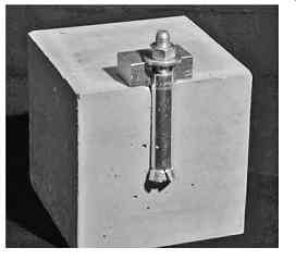
Fig. 6 Fischer Zykon bolt anchor FZA 18_80 KM12
3.2 Overview of anchor types
Anchor attachments may be divided, depending on how they work, into undercut, spread and composite anchors although there are also anchor system that combine two of these methods, such as composite spread anchors.
Undercut anchors can be divided into self-undercutting anchors and those in which the undercut is made in a preceding step. The preceding undercut is made using a special undercut tool or a special drill, swinging the drill out in a circular motion. The anchor is then placed using a setting tool (e.g. Fischer FZA-K, Figure 6). With self undercutting anchors the undercut in the concrete is made by hard metal cutting at the anchors sleeve (e.g. Hilti HDA Figure 7). Undercut anchors transmit tension loads, even if there are wide cracks, such as in the event of an earthquake, as they are anchored in a form lock way within the concrete: so the undercut must be inspected very carefully. With the products available on the market today, the undercut can be checked via colored markings which must be visible if the anchor is installed correctly.
Spread anchors can also be divided into path-controlled and force-controlled (or even torque-controlled) anchors. Path-controlled spread anchors are installed by being hammered in or driven in by machine and then checked by measuring the set depth.
Anchors can be marked to ensure they are installed to the set depth required. Force controlled spread anchors are inserted using a torque wrench, which applies the tensile or spread force required for the anchor to grip as it should (Figure 8).
Spread anchors transmit tensile loads via the grip between the spread anchor and the surrounding concrete.
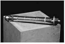
Fig. 7 Hilti undercut anchor HDA-T-22-M12_125/30

Fig. 8 Anchoring detail Liebig force-controlled safety anchor
Composite anchors consist of a composite mortar containing an embedded metal component. The composite material may be made of synthetic mortar, cement mortar or a mixture of the two. In practice, cartridge and injection systems are used. With cartridge systems, glass or synthetic capsules are fitted into the borehole. When the anchor is inserted, the cartridge is destroyed and the chambers it contains are mixed with the two components of the mortar.
Injection systems consist of the metal component to be inserted and a two-chamber injection cartridge. The composite material is mixed when it is expelled from the cartridge and injected into the borehole. The metal component is then inserted by hand or mechanically, depending on the anchor system involved.
Composite anchors work via the grip between the metal part and the composite mortar and the grip between the composite mortar and the borehole wall. The grip with the concrete means that great attention must be paid to cleaning the borehole particularly thoroughly in accordance with installation instructions.
Composite anchors can also include combinations with undercut or spread anchors (Figure 9).
The loads in a composite spread anchor are transmitted via a combination of bonding and spreading, in which the spreading is also achieved through its particular shape. This enables it to bridge even broad cracks up to 1.5mm and shows a ductile load-bearing behavior.
The load-deformation diagram for a composite spread anchor shows the wavelike course of the load very well. This is caused by the individual spread cones penetrating into the composite mortar. With smaller crack widths, all spread cones in a anchor can be assigned to the individual waves in the load-deformation diagram.
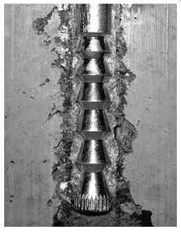
Fig. 9 Anchoring detail composite spread anchor MKT-VMZ M16
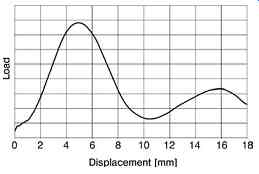
Fig. 10 Load-deformation diagram of a composite spread anchor (MKT-VMZ crack
width = 1.5 mm)
With undercut composite anchors, the load is transmitted by a combination of the bonding of mortar to the borehole walls and the mechanical form locking of the mortar in the undercut of the concrete.
3.3 Safety concept
[...]
3.3.1 Installation safety
In various nuclear power plants and nuclear facilities, there are many anchors that were not installed in the correct position, so they were replaced. According to, the anchors used to attach safety-related components must be designed such that they can be checked easily to verify that they have been installed correctly from easily recognizable, objective and doubtless criteria when setting and once installation is completed.
If plans are not followed, the structural engineer must be consulted.
Anchor fastenings must always be installed in accordance with the manufacturers' instructions, but there are numbers of other conditions which must also be observed:
- Incorrect drillings and damage to existing reinforcement should be avoided by detection.
- The anchoring plate connection area should be even, which can be achieved by applying a thin mortar smoothing layer.
- The distances required from edges causing disturbances must be maintained.
- Bores must be done at right-angles.
- Incorrect drillings must be closed with high strength concrete.
As evidence that anchor fastenings have been properly installed at nuclear power plants and nuclear facilities, an installation report must be produced for each attachment which must be verified by the client/operator and by a licensed structural engineer or the construction inspector. Instructions as to the content of such reports must be taken from those for use in nuclear power plant approvals. The data to be recorded for each location of anchor fastening are:
- application to change/notice of change
- date installed
- client's/operator's representative
- installation contractor plus professional construction manager for dowelling
- construction inspector
- fitter (training certificate)
- building
- area
- system
- anchor plate ID no.
- layout drawing
- workshop drawing
- anchor manufacturer
- product designation
- size
- material
- tools used
- borehole checks
- clean
- right-angled
- depth
- diameter
- incorrect drilling present/closed
- reinforcement damaged
- detectable cracks/local damage
- corrosive environment
- check torque
- check anchor plate
- made to workshop drawing
- plate thickness
- axis-edge distances
- through bore diameter
- concrete surface/thickness of smoothing layer at anchor
- check surroundings
- distances from adjacent fastenings
- geometric constraints.
3.4 Approvals
3.4.1 General
In Germany, non-standard construction products are qualified by a so-called General Technical Approval given from the Deutsches Institut fur Bautechnik (DIBt). A General Technical Approval confirms that a non-standard construction product or construction method may be used under German Federal State building regulations.
Since Council Directive 89/106/EEC of 21 December 1988 on the adjustment of laws, regulations and administrative provisions of the European Member States relating to construction products was introduced, the DIBt can also issue European Technical Approvals (ETAs). An ETA for metallic anchors is issued under ETAG 001. These guidelines for the European Technical Approval for metallic anchors for anchoring in concrete contains documents for assessing anchors and are divided into six parts and three annexes.
3.4.2 Tests according to DIBt guideline
Issue 9/98 of the Deutsches Institut fur Bautechnik's Guideline on 'Using anchors in nuclear power plants and nuclear installations' constitutes for the first time what tests are required over and above the General Approval in order to facilitate use of anchors for safety-related attachments in nuclear power plants.
This Guideline contains details of the tests needed to simulate the extraordinary stress situations involved in an earthquake. To prove their suitability, anchors must withstand a monotonic tension load, alternating loads at constant crack widths and varying crack widths at constant loads at a crack width of 1.5mm. These test loading conditions simulate comprehensively the accidental stresses due to earthquake actions. To obtain the characteristic tension loads, monotonic tensile tests are conducted at an open crack width of 1.0mm. The characteristic shear strength is determined by alternating shear load tests, in which anchors are exposed to 15 times the alternating shear loads in the direction of the crack. The residual load-bearing strength is then determined by a monotonic shear tension test.
The new edition of the Guideline of June 2010 revised the crack widths. This also allows for the specific crack widths that are expected at the place of use to be used in tests. However, this requires a detailed verification of the characteristic crack widths under accidental actions. An additional section has also been added on testing to determine realistic anchor shifts. Under the DIBt Guideline, anchor shifts are determined by tests in opening and closing cracks at a constant tensile load acting on the anchor and tests at alternating loads on the anchor with the crack opened, varying the crack widths as well as variable alternations of crack widths and loads. To pass these tests, anchors must satisfy a numbers of requirement defined in the DIBt Guideline.
3.5 Design and dimensioning
Anchor fastenings for use in nuclear power plants and nuclear facilities must be designed in accordance with the DIBt Guideline.
4. Corrosion protection
As fastenings cannot be accessed once they are installed, safety-related components in particular are subject to particular corrosion protection requirements, depending on the ambient conditions involved.
Inner areas will very generally be dry, so under these conditions, protective coatings or galvanizing provides sufficient corrosion protection.
Stainless steel materials must be used in outside areas and in inside areas where there are corrosion factors. Under DIN EN ISO 13918, headed studs are in group SD3 with materials 1.4301 and 1.4303 to DIN EN 10088. For steel plates, materials 1.4571 and 1.4401 to DIN EN 10088 are used.
Where particularly corrosive influences are present, such as chemical pollution, stainless materials must be checked to see whether they can be used in each case.
Anchor plates made of currently standardized materials must not be used in chlorinated atmospheres.
5. Fire resistance
Anchor plates with headed studs or metallic anchors consist of non-flammable materials and can therefore be assigned to fire protection class A1 under DIN EN 13501.
Should anchor plates be subject to specific requirements in terms of fire resistance time, structures must be tested in accordance with the test procedure prescribed for their class and their fire resistance class is to be specified according to DIN EN 13501.