AMAZON multi-meters discounts AMAZON oscilloscope discounts
FIXED GAGES AND AIR GAGES
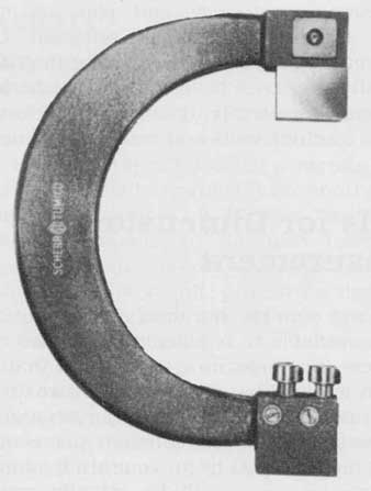
FIG. C-5 Adjustable limit snap gage Scherr-Tumico, Inc.).
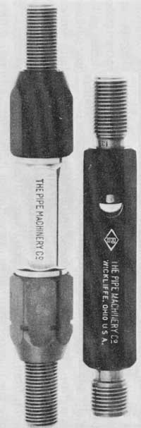
FIG. C-6 Thread plug gage (PMC Industries).
FIXED GAGES--In production machining, where large numbers of duplicate parts are produced, it may only be necessary to determine if the part is within acceptable tolerance. Many types of fixed gages are used. The adjustable limit snap gage (FIG. C-5) is used to check outside diameter. One anvil is set to the mini mum limit of the tolerance to be measured. The other anvil is set to the maximum limit of the tolerance. If both anvils slip over the part, an undersized condition is indicated. If neither anvil slips over the part, an oversized condition is indicated. The gage is set initially to a known standard such as gage blocks.
Threaded products are often checked with fixed gages. The thread plug gage ( FIG. C-6) is used to check internal threads. The thread ring gage ( FIG. C-7) is used to check external threads. These are frequently called go and no go or not go gages. One end of the plug gage is at the low limit of the tolerance, while the other end is at the high limit of the tolerance. The thread gage functions in the same manner. Thread gages appear in many different forms (FIG. C-8).
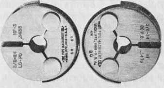
FIG. C-7 Thread ring gage (PMC Industries).
Fixed gages are also used to check internal and external tapers (FIG. C-9). Plug gages are used for internal holes (FIG. C-10). A ring gage is used for external diameters (FIG. C-11).
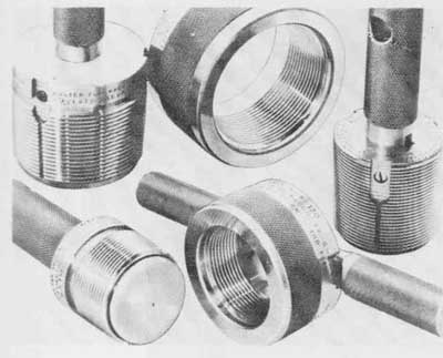
FIG. C-8 Fixed thread gages appear in many different forms (PMC Industries).
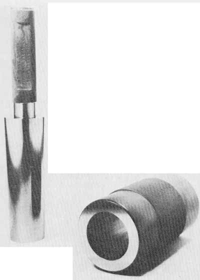
FIG. C-9 Taper plug and taper ring gage (PMC Ind).
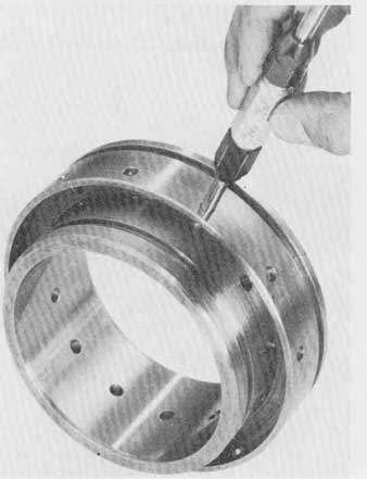
FIG. c-10 Using the cylindrical plug gage (PMC).
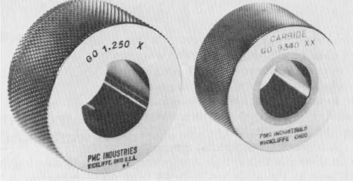
FIG. C-11 Cylindrical rings gages (PMC Industries).
AIR GAGES Air gages are also known as pneumatic comparators. Two types of air gages are used in comparison measuring applications. In the pressure-type air gage ( FIG. C-12), filtered air flows through a reference and measuring channel. A sensitive differential pressure meter is connected across the channels ( FIG. C-13). The gage head is adjusted to a master set ting gage. Air gage heads may be ring, snap (FIG. C-14), or plug types ( FIG. C-15). Air flowing through the reference and measuring channel is adjusted until the differential pressure meter reads zero with the setting master in place. A difference in workpiece size above or below the master size will cause more or less air to escape from the gage head. This, in turn, will change the pressure on the reference channel. The pressure change will be indicated on the differential pressure meter. The meter scale is graduated in suit able linear units. Thus workpiece size above or below the master can be directly determined.
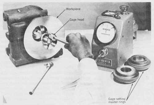
FIG. C-12 Pressure-type air gage (Federal Products Corporation).
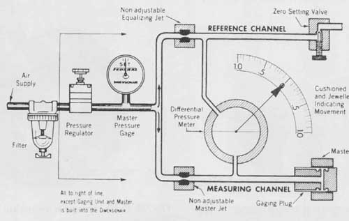
FIG. C-13 Pressure type air gage system (Federal Products Corporation).
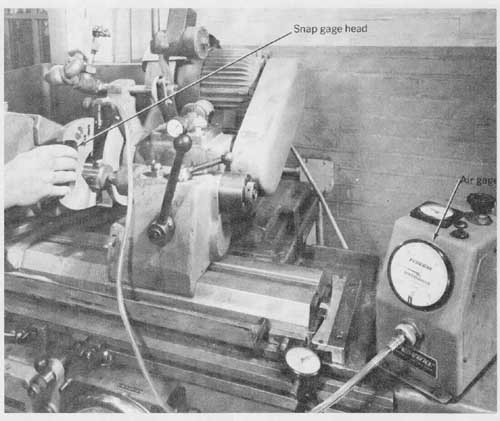
FIG. C-14 Pressure-type air snap gage (Federal Products Corporation).
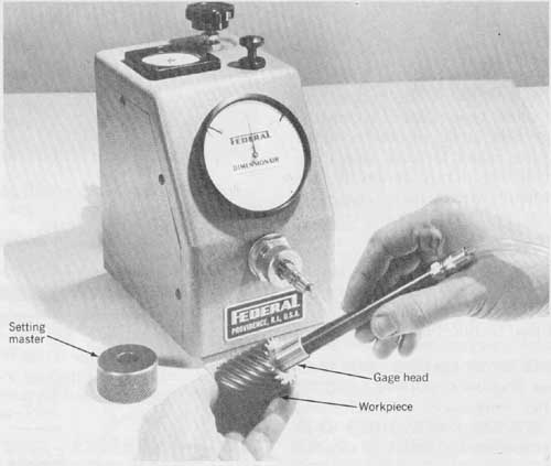 FIG. C-15 Air plug gage (Federal Products Corporation).
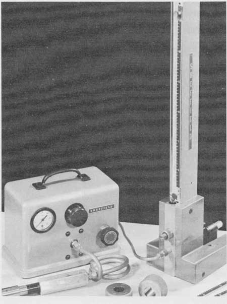
FIG. C-16 Column or flow-type air gage (Automation and Measurement Division --
Bendix Corporation).
In the column or flow-type air gage ( FIG. C-16), airflow from the gage head is indicated on a flow meter or rotameter ( FIG. C-17). This type of air gage is also set to master gages. In the case of the plug gage shown, if the workpiece is oversized, more air will flow from the gage head. An undersized condition will permit less air to flow. Differences in flow are indicated on a suitably graduated flowmeter scale. Workpiece size deviation can be read directly.
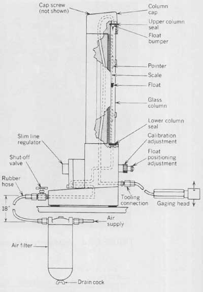
FIG. C- 17 Column-type air gage system (Automation and Measurement Division—Bendix
Corporation).
Air gages have several advantages. The gage head does not touch the workpiece. Consequently there is no wear on the gage head and no damage to the finish of the workpiece. Variations in workpiece geometry that would be difficult to measure by mechanical means can be detected by air gaging ( FIG. C-18).
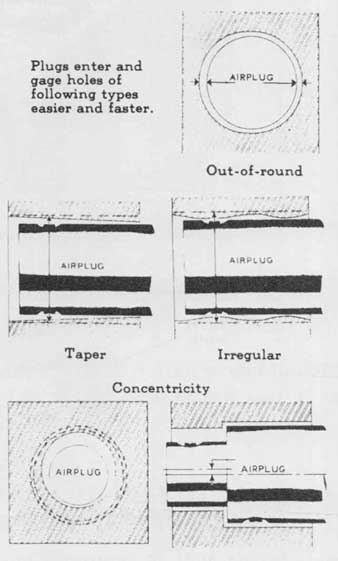
FIG. C-18 Hole geometry detectable by air gaging (Federal Products Corporation).
MECHANICAL DIAL MEASURING INSTRUMENTS
Measuring instruments that show a measurement on a dial have become very popular in recent years. Several of the common dial instruments are outgrowths from vernier instruments of the same type. Dial instruments have an advantage over their vernier counter parts in that they are easier to read. Dial measuring equipment is frequently found in the inspection department where many types of measurements must be made quickly and accurately.
DIAL THICKNESS GAGE The dial thickness gage ( FIG. C-19) is used to measure the thickness of paper, leather, sheet metal, and rubber. Discrimination is .0005 in.
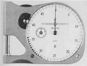
FIG. C-19 Dial thickness gage (Rank Scherr-Tumico, Inc.).
DIAL INDICATING SNAP GAGES Dial indicating snap gages ( FIG. C-20) are used for determining whether workpieces are within acceptable limits. They are first set to a gage block standard. Part size deviation is noted on the dial indicator.
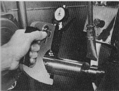
FIG. C-20 Using the indicating snap gage (Feder Products Corporation).
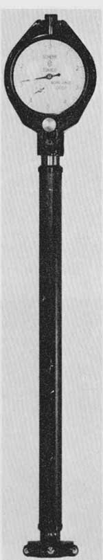
FIG. C-21 Dial bore gage (Rank Scherr-Tumico, Inc.).
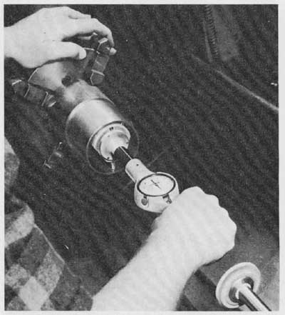
FIG. C-22 Using the dial bore gage (L.S. Starrett Company).
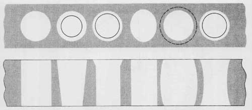
FIG. C-23 Hole geometry detectable with the dial bore gage.
DIAL BORE GAGE--The dial bore gage ( FIG. C-21) uses a three-point measuring contact. This more accurately measures the true shape of a bore ( FIG. C-22). The dial bore gage is useful for checking engine block cylinders for size, taper, bellmouth, ovality, barrel shape, and hourglass shape ( FIG. C-23). Dial bore gages set to a master ring and then compared to a diameter. Discrimination ranges from .001 to 0001 in.
DIAL INDICATING EXPANSION PLUG BORE GAGE--The indicating expansion plug gage (FIG. C-24) is used to measure the inside diameter of a hole or bore. This type of gage is built to check a single dimension. It can detect ovality, bellmouth, barrel shape, and taper. The expanding plug is retracted and the instrument inserted into the hole to be measured ( FIG. C-25).
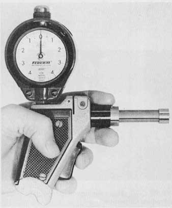
FIG. C-24 Dial indicating expansion plug bore gage (Federal Products Corporation).
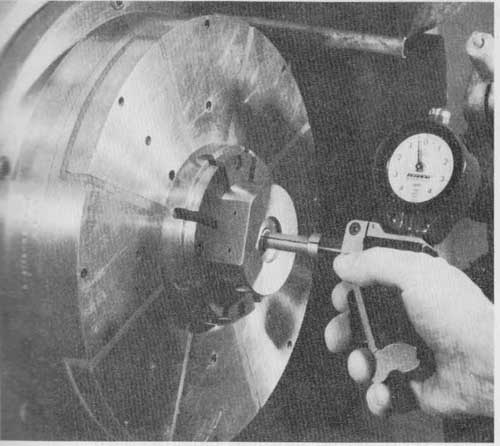
FIG. C-25 Using the expansion plug bore gage (Federal Products Corporation).
DIAL INDICATING THREAD PLUG GAGE--The indicating thread plug gage ( FIG. C-26) is used to measure internal threads. This type of gage need not be screwed into the thread. The measuring anvils retract so that the gage may be inserted into a threaded hole.
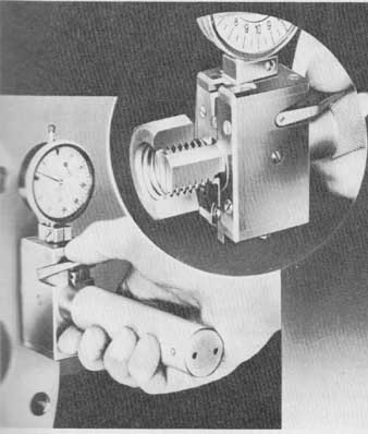
FIG. C-26 Using the indicating thread plug gage.
DIAL INDICATING SCREW THREAD SNAP GAGE -- The dial indicating screw thread snap gage ( FIG. C-27) is used to measure an external thread. The instrument may be fitted with suitable anvils for measuring the major, minor, or pitch diameter of screw threads. Discrimination is .0005 or .00005 in., depending on the dial indicator used.
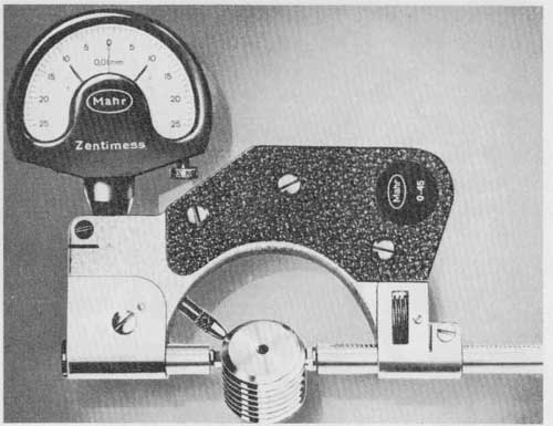
FIG. C-27 Dial indicating (Mahr Gage Company).
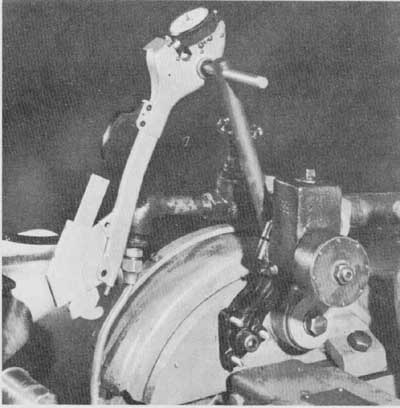
FIG. C-28 Dial indicator in-process grinding gage, in retracted position
(Federal Products Corporation).
DIAL INDICATING INPROCESS GRINDING GAGE -- Gages can be built into machining processes. The indicating in-process grinding gage is used to measure the workpiece while it is still running in the machine tool (FIG. C-28). The instrument swings down over the part to be measured (FIG. C-29). The machine can re main running. These instruments are used in such applications as cylindrical grinding. Discrimination can be .0005 or .00005 in., depending on the dial indicator used. This instrument also has its electronic counterpoint.
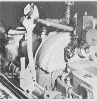
FIG. C-29 In-process grinding gage measuring the workpiece (Federal Products
Corporation).
MECHANICAL DIAL INDICATING TRAVEL INDICATORS--Mechanical dial indicators can be used to indicate the travel of machine tool components. This is very valuable to the machinist in controlling machine movement that in turn controls the dimensions of the parts produced. Mechanical dial travel indicators are used in many applications such as indicating table and saddle travel on a milling machine (FIG C-30). They may also be used to indicate vertical travel of quills and spindles. Mechanical dial travel indicators are also useful for indicating travel in metric dimensions. Discrimination is .001in., .005in., and .01 mm.
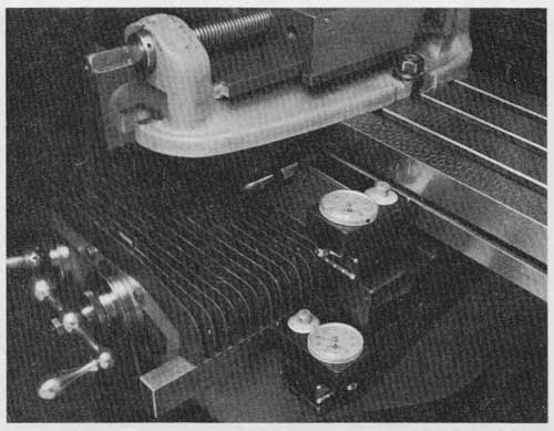
FIG. C-30 Mechanical dial travel indicators in stalled on a milling machine
( Southwestern Ind., Inc., Tray-A-Dial).
INSPECTION AND CALIBRATION THROUGH MECHANICAL MEASUREMENT
All measuring instruments must be periodically checked against accepted standards if the control that permits interchangeability of parts is to be maintained. Without control of measurement there could be no diverse mass production of parts that will later fit together to form the many products that we now enjoy.
Parts produced on a machine tool must be inspected to determine if their size meets design requirements. Parts produced out of tolerance can greatly increase the dollar cost of production. These must be kept to a minimum, and this is the purpose of part inspection and calibration of measuring instruments.
INDICATING BENCH MICROMETER -- The indicating bench micrometer, commonly called a supermicrometer ( FIG. C-31), is used to inspect tools, parts, and gages. This instrument has a discrimination of .00002 in. (20 millionths). This instrument also is available in an electronic digital model ( FIG. C-32).
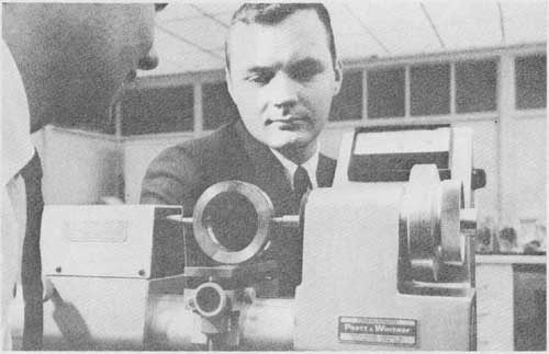
FIG. C-31 Indicating bench micrometer or super-micrometer (Colt Industries,
Pratt and Whitney Cutting Tool and Gage Division).
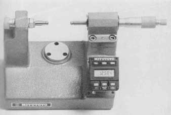
FIG. C-32 Digital electronic bench micrometer.
SURFACE FINISH VISUAL COMPARATOR -- Surface finish may be approximated by visual inspection using the surface roughness gage ( FIG. C-33). Samples of finishes produced by various machining operations are indicated on the gage. These can be visually compared to a machined surface to determine the approximate degree of surface finish.
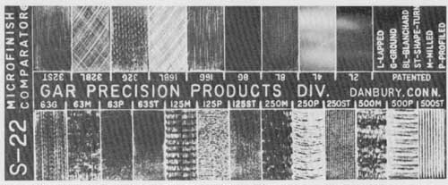
FIG. C-33 Visual surface roughness comparator gage (DoALL Company).
COORDINATE MEASURING MACHINES – The coordinate measuring machine ( FIG. C-34) is an extremely accurate instrument that can measure the workpiece in three dimensions. Coordinate measuring machines are very useful for determining the location of a part feature relative to a reference plane, line, or point.
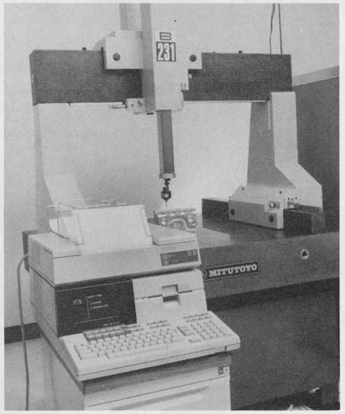
FIG. C-34 Three-axis coordinate measuring ma chine with computer and printer
(MTI Corporation).
The electronic coordinate measuring machine is an indispensable tool for the inspector and gage laboratory. Many of these instruments re computer equipped, allowing calculations to made relative to the measurements being taken. Computer printouts may be easily obtained indicating graphs of measurement, as well as graphics illustrating the parts being measured. The computerized coordinate measuring machine is another example of the integration of digital readout electronics and computers into a precision mechanical system for modern high precision measurement applications.
MEASUREMENT WITH ELECTRONICS
REMOTE GAGING -- Electronic technology has come into wide use in measurement. Electronic equipment can be designed with greater sensitivity than mechanical equipment. Thus, higher discrimination can be achieved. Electronics can be applied in remote gaging applications ( FIG. C-35). In this application, there is no direct connection to the gage head. The head is free to move with the machine tool since there are no attached wires. This facilitates use of the gaging instruments.
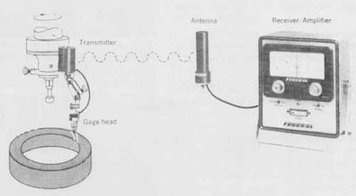
FIG. C-35 Remote electronic gaging system (Federal Products Corporation).
SURFACE FINISH INDICATORS -- Surface finish is critical on many parts such as bearings, gears, and hydraulic cylinders. Surface finish is a measure of surface roughness or profile. The measurement is in microinches. A micro-inch is one millionth of an inch. A surface finish indicator ( FIG. C-36) consists of a diamond stylus connected to a suitably graduated dial (meter). The stylus records surface deviations, which are indicated on the dial.
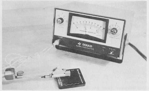
FIG. C-36 Surface finish indicator being calibrated.
ELECTRONIC DIGITAL TRAVEL INDICATORS -- Electronic digital travel indicators use a sensor attached to the machine tool. These systems will discriminate to .0001 in. and can be switched to read in metric dimensions. The travel of the machine component is indicated on digital display ( FIG. C-37). They are very useful for the accurate positioning of machine tables on such tools as milling machines and jig borer ( FIG. C-38). A sensor on the machine tool detects movement of the machine components. The amount of travel is displayed on an electronic digital display.
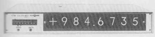
FIG. C-37 Electronic digital travel indicator display (Elm Systems, Inc.)
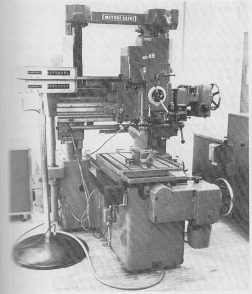
FIG. C-38 Electronic digital travel indicator system installed on a jig borer
(Elm Systems, Inc.).
ELECTRONIC COMPARATORS -- Electronic comparators ( FIG. C-39) take advantage of the sensitivity of electronic equipment. They are used to make comparison measurements of parts and other measuring tools. For example, gage blocks may be calibrated using a suitable ironic comparator.
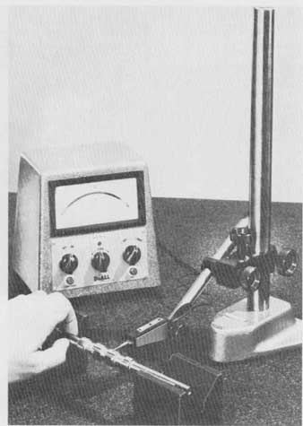
FIG. C-39 Electronic comparator (DoALL Company).
MEASUREMENT WITH LIGHT
TOOLMAKER’S MICROSCOPE -- The tool maker’s microscope (FIG. C-40) is used to inspect parts, cutting tools, and measuring tools. The microscope has a stage that can be precisely rotated and moved in two perpendicular axes. The instrument may be equipped with an electronic accessory measuring system that discriminates to .000 1 in. Thus stage movement can be recorded permitting measurements of a work- piece to be made.
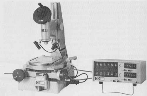
FIG. C-40 Toolmaker’s microscope (Gaertner Scientific Corporation).
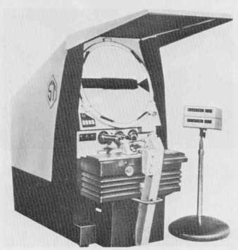
FIG. C-41 Optical comparator.
The optical comparator ( FIG. C-41) is used in the inspection of parts, cutting tools, and other measuring instruments. Optical comparators project a greatly magnified shadow of the object on a screen. The surface of the work- piece may also be illuminated. Shape patterns or graduated patterns can be placed on the screen and used to make measurements on the work-piece projection.
Optical flats are used in the inspection of other measuring instruments and for the measurement of flatness. They can be used, for example to reveal the surface geometry of a gage block or measuring faces of a micrometer (Fig. C-42). Optical flats take advantage of the principles of light interferometry to make extremely small measurements in millionths of an inch.
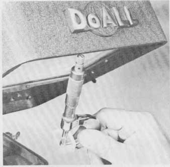
FIG. C-42 Using optical flats to check micrometer measuring faces (DoALL Company).
AUTOCOLLIMATORS--The autocollimator in FIG. C-43 is being used to check the flatness of surface plate. The mirror on the left is moved along the straightedge in small increments. Deviations from flatness are shown by angular changes of the mirror. This change is recorded by the instrument.
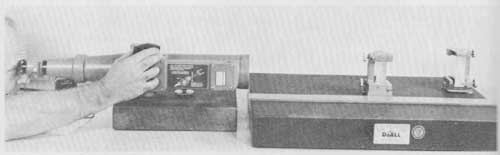
FIG. C-43 Autocollimator checking a surface plate for flatness.
ALLIGNMENT TELESCOPE--A machinist may accomplish alignment tasks by optical means. Optical alignment may be used on such applications as ship propeller shaft bearings. Portable machine tools such as boring bars may be possible by optical alignment. The dual micrometer alignment telescope ( FIG. C-44) is a very useful alignment instrument. The micrometers permit the deviation of the workpiece from the line to be determined.
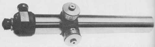
FIG. C-44 Dual micrometer alignment telescope (DoALL Company).
LASER INTERFEROMETER--The term laser in acronym for light amplification by stimulated emission of radiation. A laser beam is a coherent beam. This means each ray of light follows the same path.
Thus it does not disperse over long distances. This property makes the laser beam very useful in many measurement and alignment applications. For example, the laser beam may be used to determine how straight a machine tool table travels ( FIG. C-45). Other uses include the checking of machine tool measuring systems ( FIG. C-46).
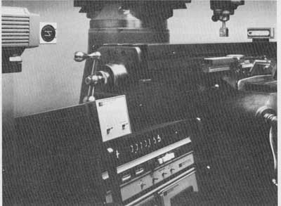
FIG. C-45 Laser interferometer being used for straightness determination.
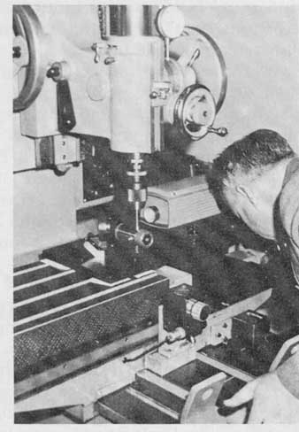
FIG. C-46 Laser interferometer checking the measuring system on a jig boring
machine.