AMAZON multi-meters discounts AMAZON oscilloscope discounts
Process control is a method of manufacturing that uses formulas and recipes rather than assembling components to produce products. The primary way to determine if an application falls under the category of process manufacturing is whether the end product can be returned to its basic components. For example, an automobile can be disassembled and its components returned to stock, whereas a bottle of shampoo cannot be returned to its basic ingredients.
Process manufacturing is used in the chemical, food and beverage, pharmaceutical, biotechnology, and packaging industries. In the process industry, ingredients, formulas, and bulk are the elements of the end product rather than parts, assemblies, and components. Raw materials are also processed into intermediate forms that can be used in the manufacture of components. The materials that automated machines process all have their own special properties and techniques that are associated with their manufacture. There are many similarities in the processing of metals and plastics. For instance, both involve the mixing of different elements in a molten state and the machining or forming of shapes.
Automated machinery is created by combining the components and machine subsystems described previously in this guide.
Automated production lines use a combination of custom machines and original equipment manufacturer (OEM) equipment to assemble or produce an end product.
Some machines are fairly standardized, such as hydraulic presses, web-handling equipment, and injection molding machines. These machines are often made in several sizes and configurations, and only the tooling needs to be customized. They are often manufactured by OEMs who specialize in a specific kind of machinery. Other machinery is often customized to fit a specific application, such as assembly and gauging machinery. Custom machine builders often use a combination of OEM products and custom machines, moving components and products through a production or assembly line to produce the end result. The combining of the various machines and control systems into a single entity is a process known as integration.
1. Chemical Processing
Chemical processing involves combining or mixing ingredients and often changing their temperature or pressure. Some chemicals or compounds are produced in bulk form for use in further processing, including commodity chemicals in solid or liquid form, polymers or plastics, and petrochemicals. These products are generally packaged or contained in bulk for shipment to other facilities or processors.
Bulk chemicals may undergo further processing to produce specialty or fine chemicals, such as adhesives, sealants and coatings, industrial gases, electronic chemicals, catalysts, and cleaning compounds. They are also used in consumer products, such as soaps, detergents, lotions, and cosmetics. The life science industry also uses bulk chemicals and compounds in the production of pharmaceutical drugs and medicines, vitamins, and diagnostic products. Because of the higher research and development costs and government specifications and regulations, these products are usually produced in a controlled laboratory environment and are more costly.
Key process variables in the production of chemicals and compounds are residence time (lowercase Greek letter tau), volume (V), temperature (T), pressure (P), concentrations of chemicals (C1, C2, C3. . . ., Cn), and heat transfer (h or U). Chemical processing is concentrated around the control and monitoring of these variables.
Chemical production and processing can be very hazardous because of the reactionary nature of chemicals. Pressures, temperatures, acidity, and quantities must all be monitored and controlled very precisely. This requires instrumentation and visualization using a wide range of products. HMIs are used in the field and in control rooms to display process diagrams and provide control and detailed alarms. P&ID diagrams are used to design and troubleshoot chemical processing systems and may also be accessed through computers or HMIs.
Valves for controlling the flow of liquids and gases in a process are often analog; they not only completely open or close, but also move to intermediate positions. These are known as proportional valves. They also usually have a feedback sensor to verify position, although sometimes a downstream flow sensor or pressure feedback is used. Process variables are monitored using standardized limits such as H and L, indicating values within which operation is considered normal, and HH and LL, indicating limits that require alarms and may initiate shutdown.
Because of the caustic and explosive nature of many chemicals, safety is an overriding concern in the chemical industry. Controls are often redundant and mechanical elements are designed with high safety margins. IS and explosion-proof products are used extensively within chemical process facilities. Both PLCs and DCSs are used for control along with stand-alone temperature and PID controllers. The physical layout of chemical processing facility generally includes elaborate piping with multiple holding and containment vessels.
Vessels designed to contain chemicals as they undergo mixing or property changes are known as reactors. These are designed to maximize their value for the given reaction, providing the highest yield while minimizing cost of materials or energy. Basic vessel types include tanks in various shapes or pipes (tubular reactors). They may operate in a steady state, where materials flow into and out of the system continuously, or a transient state, where a process variable such as heat or pressure is changed over time.
Three main basic models for estimation of process variables are used in chemical processing; the batch reactor model (batch processing), the continuous stirred tank reactor model (CSTR), and the plug flow reactor model (PFR). Catalysts may require different models or techniques than these three basic models, such as a catalytic reactor model.
2. Food and Beverage Processing
Food processing uses meat, grain, or vegetable components to produce packaged food products for commercial use. Like chemical processing, food processing involves the control of temperature and often the mixing of ingredients. Administration of the food-processing industry regulations in the United States is monitored by the Food and Drug Administration (FDA) and the United States Department of Agriculture (USDA). Of primary concern is sanitation and the elimination of contamination.
Special techniques specific to the food industry include clean in-place, flash freezing, spray drying, and various filtration methods. Water treatment is also an important part of the process because of the necessity of cleaning equipment with caustic substances and federal regulations involving wastewater discharge.
Product or material handling and packaging are also integral to the food-processing industry.
Food-processing machinery may be made by OEMs who specialize in specific aspects of production or by custom machine builders who are knowledgeable of the special requirements of food processing.
Food-processing machines may be used for the preparation of ingredients (chopping or cutting, crushing, peeling, or molding into shapes); the application or removal of heat (cooking, baking, or freezing); mixing of ingredients or seasoning; or product filling. Most food service equipment is built using stainless steel and techniques allowing for pressurized wash-down of equipment. Great care is taken to ensure equipment does not have crevices where contaminants can lodge.
Controls in the food- and beverage-processing industries are similar to that of chemical processing, although mostly PLC controlled.
Instrumentation is used to measure temperatures and flow rates, sometimes using individual controllers with data read back into a SCADA or monitoring system.
Food is produced by several different methods. One-off or individualized production does not lend itself to automated methods.
An example of this would be wedding cakes or cake decoration. Batch production is commonly used in bakeries, where a certain number of products of the same size and ingredients are made on a periodic basis. Equipment is set up with an end number in mind, and ingredients are ordered based on an estimate of the demand. Many OEM food production machines are constructed with recipe, batching, and counting features built into the software. Weighing and liquid measurement are also an important part of the batching process. Mass production is a continuous method of producing products, such as canned or packaged foods, and individual items, such as candy.
Product passes from one stage to another along a production line in this method.
Beverage processing involves the formulation of the product as well as the bottling or packaging. Basic ingredients may be mixed in a batch form to control proportions accurately or in a continuous manner.
Some beverages, such as beer or whiskey, require long periods where ingredients age or ferment in a tank at a specific temperature. Others can be continuously processed directly into a bottling or packaging area. Bottling is a high-speed process with many OEMs involved in making standard or semicustomized machinery. Packaging equipment, from sterilized product containers to bulk shipping, is also a major part of both the food- and beverage-processing industries.
Like the chemical-processing industry, food and beverage processing involves a great deal of process visualization. HMIs and integrated control systems allow the viewing of the entire process from raw ingredients through packaging. Many control component vendors have packaged templates specific to the food and beverage industry with three-dimensional images, recipe management, and historical data collection. There are also quite a few integrators and custom machine builders who specialize in food- and beverage processing equipment.
3. Packaging
The packaging industry encompasses the containment, labeling, orientation, and material handling of products for distribution, storage, and sale. Products are packaged in different ways, depending on the stage of production and type of product. Many products are produced in bulk form but must be packaged as individual units for shipment or sale.
Packaging can be described in three broad categories. Primary packaging is the first layer of material that surrounds or holds the product. This layer is often consumer packaging that is labeled for marketing and comes in direct contact with the product. Secondary packaging is often used to group primary packaging together, usually also labeled for consumer use. Tertiary packaging is used for bulk handling, storage, and shipment.
Packaging materials are generally made of some form of plastic or cardboard, although in the food and pharmaceutical industries, glass and metals are also widely used. Packaging machinery generally takes these materials in a rolled or collapsed form and uses it to envelop the product.
Common methods of primary packaging include shrink-wrapping, cartoning, blister packing, and vacuum packing. These methods also lend themselves to easy labeling for consumers by application of adhesive labels, direct printing, or printed cartons and bags. Secondary methods also include cartoning, bagging, and shrink-wrapping.
Tertiary packaging uses corrugated cardboard, palletizing, bag-in-box, and other techniques. Packaging for transport is typically less concerned with marketing and the appearance of a packed unit than with protection and ease of handling.
Packaging machinery can be purchased as off-the-shelf equipment from many OEMs. Labelers, check-weigh systems, baggers, case erectors, sleeve-wrappers, and shrink-wrappers are made in standard sizes by many manufacturers and can be ordered with short lead times. They are usually adjustable for various standardized sizes of packaging and labeling materials. Machinery can also be customized by many manufacturers from a standard design. Some packaging machinery must be custom-built because of special requirements related to material handling, package size, or speed requirements.
End users often customize or manufacture their own packaging machinery in-house.
Considerations when choosing packaging machinery includes type of packaging and its final appearance, floor space requirements, throughput, reliability and maintainability, labor requirements to operate machinery, and flexibility of the equipment related to product sizes and changeover. Packaging machinery is often built into a line involving material handling and an integrated control system.
Accumulating, orienting, and collating are commonly part of the material-handling process as well as inspecting and weighing of product. Machine vision and metal detecting are common in the packaging industry. FIG. 1 shows a typical packaging line layout.
Liquid packaging includes filling, capping, closing, seaming, and sealing. Because the packaging of liquids may involve foods or beverages, cleaning and sterilizing may also be part of this process.
Cooling and drying are also common in the material handling and packaging of products.
The use of plastic wrap involves shrinking film using ovens and heated air and the sealing of packages using bar sealing equipment.
Temperature and time are important variables in this process and are often controlled by discrete devices, such as temperature controllers, timers, and variable speed conveyors. Packaging machinery uses a wide range of technologies ranging from simple control and mechanical components to high-speed servo and robotic systems.
Palletizers are used to arrange boxes and cartons in layers on plastic or wooden pallets. They are often robotic and can be programmed for different patterns. Pallets are then usually stretch wrapped using a rotary wrapper or by hand and transported by forklift to the shipping area.
Labeling may be applied to packages by means of adhesive labels from a dispenser or directly printed onto cartons, bags, or boxes.
Labelers are often controlled by means of a part detection sensor acting as a trigger and may also use an encoder or other speed detection device to control spacing. Bar coding is also an important part of the labeling industry. Bar codes may be preapplied to labels or printed directly on the product.
======
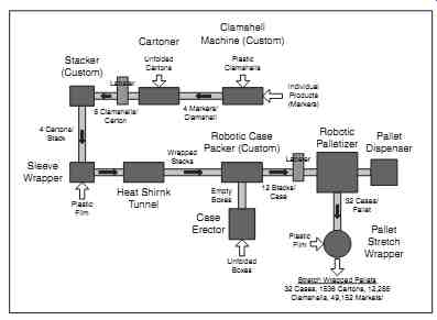
FIG. 1 Packaging line layout.
Stacker (Custom) Heat Shirnk Tunnel Case Erector Robotic Case Packer (Custom) Robotic Palletizer Pallet Dispenser Pallet Stretch Wrapper Clamshell Machine (Custom) Cartoner Sleeve Wrapper Unfolded Cartons 4 Cartons/ Stack 8 Clamshells/ Carton Plastic Film Plastic Film Wrapped Stacks 12 Stacks/ Case 32 Cases/ Pallet Stretch Wrapped Pallets 32 Cases, 1536 Cartons, 12,288 Clamshells, 49,152 Markets! Unfolded Boxes Empty Boxes 4 Markers/ Clamshell Individual Products (Markers) Labeler Labeler Plastic Clamshells
======
4. Web Handling and Converting
A web is a continuous piece of material. Paper, fabric, and some extruded materials are examples of a web. Webs are usually moved through processes using rollers, which may also serve to apply tension, heating, or cooling to the material. Webs may be processed directly from the manufacturing of the material or from rolls or coils.
Common materials processed in web form include Nonwovens, films, textiles, foams, and paper.
Because webs are moved continuously, they can be processed at higher speeds than individual sheets of material. Common uses of web processing include bonding layers of material together; cutting material into sheets or slitting it into smaller rolls; cutting or punching pieces out of it; or passing the material through other heating, cooling, or chemical processes.
Web-handling machinery is usually composed of individual drives arranged in a linear fashion with sections performing different operations on the web sequentially. Web guiding and tensioning are important facets of controlling webs, and a variety of products are manufactured to help in these areas. Web guides and steering mechanisms sense the position of the edges of the web and adjust rollers in real time to correct for misalignment. These are often placed immediately before critical sections of a line, such as printing. Tension may be monitored by load cells and strain gauges, or torque feedback may be sensed by roller drives. Gaps between rollers must often be controlled and adjusted carefully for tensioning or product thickness.
Pull units are drive and roller sections that have methods for these adjustments built in. They may consist of full-width or "nip" rollers at the web edges. FIG. 2 shows a web being processed.
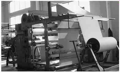
FIG. 2 Web line.
Accumulators are used to isolate sections of web from the tension effects of other sections. They also store material while rolls are being changed. Accumulators are sometimes built with multiple festoons or may take the form of a simple take-up mechanism. Unwinders and winders pay out rolls of material and wind them up at the ends of the process. Splicers are placed between the unwinding station and an accumulator to allow web to feed out continuously. These stations may be fully automated or operator assisted.
Slitters are used to cut webs lengthwise on a continuous basis.
They may have stationary blades or rolling knives and are usually adjustable for different widths.
Some operations, such as heating, cooling, and slitting, are continuous processes, while other operations, such as ultrasonic welding, punching, or cutting across the web, may be done by starting and stopping or slowing the web between accumulators.
Converting is the process of turning raw materials, often in rolled or sheet form, into new products. Common materials used in the converting process are woven and nonwovens, paper, adhesives, rubber, foam, and plastics.
Continuous rolls of material are threaded into processing machinery, which then performs intermediate or final operations to produce product. An example of converting is taking a web of two layers of plastic, fusing the edges together and sealing the ends, and cutting it to produce plastic bags. Common operations in the converting process include coating, application of adhesives, ultrasonic welding, or other types of material bonding, sealing, and patterning. Converting methods are also often used in the assembly process.
5. Metal, Plastic, Ceramic, and Glass Processing
Processing of metals, plastics, ceramics, and glass are similar in several ways. They all involve the combination of raw materials and often the application of heating, cooling, chemicals and pressures.
They are processed in their solid and liquid, or molten states. They often pass through several intermediate forms and shapes before being made into a final product.
5.1 Metals
Raw metals are extracted from the earth in the form of ores that must be processed to extract the pure metals. The initial processing may use chemical or electrolytic reduction, pyrometallurgy (high temperature), or hydrometallurgy (aqueous or water-based chemistry). When an ore is an ionic compound of a metal with impurities, it must be smelted to extract the pure metal. Ores such as iron, aluminum, and copper are typically mixed with other compounds or chemical elements, which must be separated out by breaking the bonds either electrically or chemically. Many common metals, such as iron, are smelted by combining the ore with carbon as a reducing agent at high heat.
To separate aluminum from the ore bauxite-a common practice in extractive metallurgy-carbon and electricity must be introduced.
The aluminum is extracted using an electrochemical process in a carbon-lined vat or "cell" using molten cryolite or synthetic sodium aluminum fluoride. Aluminum smelters consume a great deal of electricity because of the very high melting point of the metal.
Copper ore contains a very low percentage of copper metal and goes through several stages to purify the metal. The ore is first ground and separated from other minerals. It then undergoes hydrometallurgical or froth flotation procedures to further refine the metal before being smelted. The smelter produces about a 70 percent copper sulfide, which is then further refined and purified using electrolysis.
Purified metals or alloys are usually made into a solid form, such as ingots, sheets, or coils, and shipped to other facilities for further processing.
Alloys
An alloy is a mixture of materials in which the major component is a metal. Alloys of iron are the most common, including tool steel, cast iron, and stainless steel. Alloying iron with different amounts of carbon produces low-, mid-, and high-carbon steels. More carbon reduces the ductility but increases the hardness and strength of steel.
Cast iron is an alloy containing iron, carbon, and silicon. It is melted and poured into molds to form different shapes, which are then often processed further. Common uses for cast iron include motor housings, pipes, and machine parts. Cast iron can be brittle, so other elements are often alloyed with it to increase its malleability, hardness, or tensile strength. Cast iron has a relatively low melting point and is easy to machine.
Stainless steel is made by alloying carbon steel with chromium.
Other elements, such as nickel and molybdenum, are sometimes added to make it less brittle or increase hardness. Stainless steel is used primarily for its resistance to corrosion. It is used in food processing and medical devices as it can be easily sterilized and does not need painting or other surface coatings. Stainless steel is commonly formed into coils, sheets, plates, bars, wire, or tubing before being further processed.
Copper, aluminum, titanium, and magnesium are other common alloys produced for commercial use. Copper and its alloys are often used for electrical wiring, while alloys of aluminum, titanium, and magnesium are valued for their high strength to weight ratios. Alloys designed for special or very demanding applications may contain more than 10 elements.
Smelters are major users of automation. Because of the high temperatures and toxic fumes, it is difficult for operators to work in close proximity to the molten materials. Material handling, power distribution, and process control are important elements of metal alloying and refining. Visualization of the process using HMIs and SCADA (System Control And Data Acquisition) are common.
Metal Processing
Once a metal has been alloyed into its final constitution, it must be brought into a useful form. It is common to melt the raw alloy into ingots for further treatment or use a continuous process to form it into sheets or plates. This is often done at the smelter prior to shipping using extrusion or rolling mills.
Casting is a forming process that requires melting a metal and molding it into a shape. There are a variety of methods to accomplish this. Molten metal may be poured directly into a form using investment or "lost wax" casting. Metals may also be forced into a die at high pressure (die casting), poured into a mold made of sand (sand and shell casting), or formed by rotating the molten materials within a mold (centrifugal, spin, and rotocasting).
Extrusion uses metals in a liquid, plastic, or solid state to shape it by forcing it through a die. The metal is pushed or drawn at high pressure through an opening of a desired shape. It is then often stretched to straighten it. The process may be continuous or produce individually shaped pieces using a "blank" or billet. Extrusion presses may be hydraulically or mechanically driven.
Wire is usually made by drawing annealed metal through a hole in a die. Dies used for producing wire are often called draw plates and may have more than one hole for pulling multiple wires.
Annealing, a heat treating process, makes metals or wires more flexible or ductile. Wire is often drawn more than once, making it thinner each time. It can be drawn up to three times before it needs to be annealed again.
Thicker cables or stranded wire is woven or twisted from individual wires by specialized equipment, often in machinery located directly after the draw plate. Wire is also woven into wire netting or wire cloth and mesh and is often further treated with heat or chemicals to change its properties after being drawn. Common metals used for wire are copper, aluminum, silver, platinum, iron, and gold, which have the ductility that make them suitable for wire.
Rolling is a technique that passes metal stock through a pair of rollers. This may be done at high temperatures, above the re-crystallization temperature of the metal, or at lower temperatures; processes known as hot rolling and cold rolling, respectively. Metals may be rolled into rectangular cross sections as sheets or plates, rolled into a very thin sheet called a foil, or passed through consecutive rolls to shape the cross section, a process called roll forming. Roll forming is usually performed on coiled steel rolls. FIG. 3 shows a roll former with progressive forming dies.
If metals are rolled thin enough, they may then be rerolled for shipment. Larger rolls are often slit into smaller rolls by other facilities.
The smaller rolls may then be further processed using cutting, punching, or pressing techniques.
Forging uses pressure to form metals into desired shapes. Like rolling, forging may take place at temperatures above or below the re-crystallization temperature of the metal, known as hot or cold forging. Cast or formed pieces may be further processed after the shape is cooled. They are usually finished using presses or machine tools.
Drop forging uses a heavy weight or "hammer" to strike and deform the workpiece. Drop forging uses open or closed dies to shape the material. Open die drop forging is often called smith forging, while closed die forging is known as impression forging. In impression forging, the workpiece is often moved through a series of cavities in the die to achieve its final form. The hammer may be dropped several times, depending on the complexity of the part being forged.
Press forging applies a continuous pressure to the metal as it is formed. Like drop forging, dies can be partially open, allowing material to flow outside the die, or completely closed. Presses are typically hydraulic when used for forging. Press forging allows for more complete control of the forging process since the rate of compression can be timed.
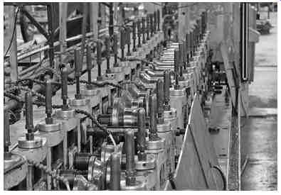
FIG. 3 Roll former. (Mills Products.)
Another form of press forging is known as upset forging. This is a method of increasing the diameter of a workpiece by reducing its length. Dies in upset presses often have multiple cavities and are used to compress rods or wires (thin rods) into the raw stock for bolts, screws, and other fasteners. The raw stock is then threaded in other machinery. Engine valves and couplings are other products often produced by upset forging.
Presses are also used on sheet metals to form shapes by drawing or stretching it. If the metal is stretched longer than its diameter, it is known as deep drawing. Pressure and lubrication are important variables used in the drawing process, along with the rate of die movement. Another common use of presses is to punch shapes into sheet metal or to "coin" parts, impressing a pattern onto the surface.
Presses often have self-contained control systems. Hydraulic presses have pumps to move hydraulic fluid through cylinders and often also have a coolant pump. Motor starters or variable frequency drives are usually part of the control panel. Proportional valves and positional feedback are also typical elements of a press. Typically, presses are controlled by a PLC also handling safety and other actuators and sensors. FIG. 4 shows a hydraulic press with the die removed.
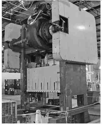
FIG. 4 Hydraulic press. (Mills Products.)
Hydroforming applies water at high pressure to the inside of a closed metal shape such as a pipe. This allows the forming of contoured shapes such as curved handles. Pressurized liquid is introduced into the shape during the final closing of a hydraulic press die.
Powder metallurgy (P/M) is the compression of metal powder into a form of the desired shape. A number of different metals and their alloys are used in the P/M process, including iron, steel, stainless steel, copper, tin, and lead. Powders are produced using atomization (transforming a stream of molten metal into a spray of droplets that solidify into powder), chemical methods, and electrolytic processes.
Powders can then be blended and ground further in a ball mill.
Forming of components is done using a variety of pressing techniques. Mechanical presses such as crank and toggle presses are often used if a high production rate is required; however, forces are limited. Hydraulic presses are used for higher loads, but production rates are lower. The formed component is then heated (but not melted) to allow a metallurgical bond to form between the particles. The forming or compacting process is usually done at room temperature in a die. The result of this operation is a briquette or green compact with a solid form. This shape is quite fragile and must be handled carefully.
The second step in the formation of a P/M component is the heating of the component, typically in a hydrocarbon gas atmosphere.
Formed briquettes are usually heated to between 60 and 80 percent of the melting point of the constituent with the lowest melting point.
This process is called sintering. The result is a formed metal solid that is smaller than the original component. Secondary operations such as restriking or re-forging, sizing, heat treatment, impregnation, machining, grinding, and finishing may also be part of the process.
Small parts are often made using P/M techniques because the density of the metal is more uniformly controlled.
Other metal-processing methods include various cutting and machining techniques. Shearing, sawing, and burning are common cutting methods. Erosion methods such as water jet or electric discharge are also used to cut metals. Wire electrical discharge machining (EDM) uses electrical current to erode material and allows detailed cutting beyond the capability of chip-producing processes.
Machining methods are chip-producing processes used to shape metals. One of the most common machining techniques is drilling, which uses the point of the tool to make holes in material. Milling uses either the side of a tool or its face to remove material. Grinding and polishing are other machining methods. Turning uses the rotation of a workpiece and a fixed or slowly moving tool to remove material.
A common machine using this technique is a lathe. Where heat is generated by tool friction, cutting fluids or coolant are often used to remove heat from the workpiece. Coolant is usually recaptured, filtered, and cooled before being reused on the product.
Machine tools are often automated; servo systems precisely control speeds and positions. Computer numerical control (CNC) machines allow CAD and CAM programs to be interpreted and move tooling automatically to produce a part. Tools are often automatically changed using robotic "tool changers." Robotic operations may also be used to move parts from station to station within a workcell.
CNC machines are usually programmed using G-code; however, other languages such as Step-NC and control languages similar to BASIC are commonly used also.
After forming metals into the desired shape, the metal is often treated using chemicals, heat, and electricity to change its properties.
Heat treatments are generally used to change the ductility, malleability, or hardness of metals, while chemicals and coatings are used to change the finish or corrosion resistance of metals.
Galvanization applies a protective coating of zinc to steel or iron to prevent rusting. Anodization increases the thickness of the natural oxidization layer on metal parts using an electrical process, which improves corrosion resistance and provides a good surface for adhesives or paints.
Like the smelting industry, metal processing uses automation extensively. Thicknesses and lengths must be accurately measured and roll speeds controlled and monitored. As with other industries, there are many OEMs that manufacture equipment specific to metal processing. Machines are often built around standard equipment to provide material handling and safety features. Production lines are built using individual machines, often taking product from a raw sheet, ingot, or blank to its finished form.
5.2 Plastics
Plastics are made from organic materials, usually synthetic or semi-synthetic solids. Crude oil is processed using a method called catalytic cracking to break it down into substances such as gasoline, oils, ethylene, propylene, and the butylenes. Natural gas is processed using thermal cracking to produce many of the same components.
The petrochemical monomers or raw materials that are derived from these substances include ethylene glycol, isobutene, isopropyl benzene, toluene, chloroprene, styrene, and many more. These raw materials are then processed further to produce rubbers, adhesives, lubricants, asphalts, and plastics.
There are two categories of plastics: thermoplastics and thermosetting polymers. All plastics are formable when they are heated, thus the prefix thermo. Thermoplastics do not change their chemical properties when they are heated and can be formed or molded multiple times. Polyethylene, polypropylene, polystyrene, polyvinyl chloride (PVC), and polytetrafluoroethylene (PTFE) are all examples of thermoplastics.
Thermosets or thermosetting polymers are formed into a shape one time. After they are formed, they remain solid. Thermosets are usually liquid or malleable before they are cured by heat or chemical processing. They are usually stronger than thermoplastics but are also more brittle. Epoxy resins, Bakelite, vulcanized rubber, Duroplast, and polyamides are examples of thermoset materials, as are many adhesives.
Additives are used to change the hardness, color, flammability, biodegradability, or other properties of the plastic. These may be added during the preprocessing stages of creating the plastic or added later while forming the part.
Extrusion
Plastics extrusion is a process that forms plastic material into a continuous profile. Extrusion is used to produce pipe and tubing, adhesive tape, wire insulation, and various plastic framing profiles.
Raw thermoplastic material in the form of beads or pellets is fed from a hopper into the rear part of the extruder barrel. A rotating screw forces the beads, also called resin, forward into the barrel.
Additives are sometimes mixed with the resin to color the plastic or make it UV resistant. The barrel is heated to melt the plastic, usually to between 200°C (392°F) and 275°C (527°F), depending on the polymer.
Heating is often done in stages, using different controllers for each stage, allowing the beads to melt gradually. Pressure and friction within the barrel contribute to the heat of the melt. Sometimes air or water is used to cool the polymer if the material becomes too hot.
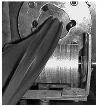
FIG. 5 shows a thermoset material being extruded from a die.
After the molten plastic leaves the barrel, it is passed through a screen pack and breaker plate to remove contaminants. It then enters the die, where it is shaped to the desired profile. After exiting the die, the material is pulled through a cooling section, typically a water bath. Plastic sheeting is sometimes fed through cooling rolls. After cooling, secondary processes may be performed, like applying adhesive to tape. The finished product is then cut into sections, rolled, or spooled.
Injection Molding
Plastic injection molding is a process that can be used for both thermoplastics and thermosets. The initial stages of injection molding are similar to that of plastic extrusion, with beads or resin being fed into a heated barrel from a hopper. It is then injected into a mold cavity, where it cools and hardens in the shape of the mold. Molds are usually made of steel or aluminum and are precision machined to form the features of the part.
Thermosets typically use two different materials that are injected into the barrel. The materials begin chemical reactions that eventually harden the material irreversibly. This can cause problems if the material were to harden inside the barrel, so minimizing the time the material is in the barrel and screw is important.
Molds often have channels between cavities to allow flow of material, called sprue, which must be removed from the mold and the product. The mold also needs to be separated to remove the part.
This separation, along with ejector pins that help push the part out of the mold, creates lines and marks on the product. Material that needs to be removed from the product is called flash and must often be removed manually. FIG. 6 shows a commercially available injection molding machine.
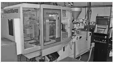
FIG. 5 Extrusion.
Injection molding is a common process for manufacturing parts of every size. Injection molding machines are usually manufactured by OEMs who specialize in plastics. They are usually PLC controlled and are configurable through an HMI. Recipes and control of temperatures, times, and speeds are standard features. Automatic unloading of parts is often a feature of injection molding machines.
Thermoforming:
Plastic sheets or films can be formed into a mold by heating the material and pulling it into a mold with vacuum. This process is called thermoforming. Material must then be trimmed from the edges after cooling. Often, secondary processes such as drilling or punching are performed while the part is still on the machine. This and the trimming operation can be incorporated into the control system if required.
Automated thermoforming machines are much simpler to manufacture than extrusion or injection molding machines. They are often made by custom machine builders and machine shops rather than OEMs since they consist of essentially a frame to hold the mold, heaters, and plumbing for vacuum. If water or air cooling is necessary, this is usually easy to implement also.
Thermoforming is used on products such as cups, lids, and trays for the food industry; blisters and clamshells for the packaging industry; and specialty components for the medical field. All of these are examples of thin gauge thermoforming. Large production machines making thousands of parts an hour are often used for thin gauge products. Parts can be formed continuously at high speed using a sheet or film on a roll, similar to web processing. Indexing chains are often used to transport the material across molds and through ovens and cooling zones. These chains may have pins or spikes to hold the material between the molding areas, helping in the transport process. The remaining material is rolled up at the end of the line after formed parts have been removed. This material can then be recycled by grinding it up in a granulator.
FIG. 6 Injection molding machine. (Hope Industries.)
Thick gauge products are usually made at a much slower rate because of the longer heating and cooling times. Unlike thin gauge forming, thick gauge processing usually involves loading and indexing individual sheets through multiple stations. Sheets are placed or clamped into a frame at a load station. Stations may be indexed linearly or on a rotating carriage. The first station heats the sheet, usually in a pressure box with mating molds closed over the sheet. Vacuum and pressurized air are used to pull or push the sheet into the contours of the mold. Some molds will have movable sections that help push the material into parts of the mold with an actuator; this is called a "plug." Plug assists are used for taller or deep-drawn parts in addition to vacuum to help distribute the material evenly.
After a defined forming time, the mold is opened. At the same time, the vacuum is removed and a burst of air is applied to the mold-an action known as air eject. A stripper plate may also be actuated to assist in the removal of the formed sheet. The formed sheet is then indexed into a station that cools the sheet and cuts the parts out of the sheet with a die. Automotive door and dashboard panels, plastic pallets, and truck bed liners are examples of thick gauge thermoforming.
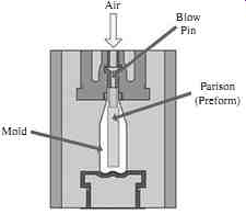
FIG. 7 Blow molding.--- Mold Air Blow Pin Parison (Preform)
Blow Molding:
Hollow plastic items, such as bottles, are formed in a process called blow molding or blow forming. There are several techniques used in this process, including extrusion blow molding (EBM), injection blow molding (IBM), and stretch blow molding (SBM). Deformable or moving dies are also sometimes used in the process.
The blow molding process begins with a plastic form called a preform, or parison-a tube of plastic with one end open for air injection. The parison is clamped into a mold, the parison is heated, and compressed air is blown into the opening inflating the form into the shape of the mold. After the plastic has cooled and hardened, the mold is opened and the part ejected. Thicker parts often have excess flash still attached to the part that must be trimmed. For cylindrical parts, this is usually done using a spin trimmer, which rotates the part while trimming material with a titanium blade. FIG. 7 illustrates the blow molding process.
Stretch molding first uses a preform that often has premolded features, such as a threaded neck for a cap connected to the parison.
These preforms are then reheated in "Reheat Stretch" blow molding machines. The stretching of the plastic induces strain hardening of the plastic, which is useful for bottles that contain carbonated beverages.
EBM is used on continuous profile such as hoses and pipes. This is done in much the same way as standard plastic extrusion, although air is blown around a mandrel through the center of the tube.
Common plastics used in the blow molding process include PET, PC, PVC, HDPE, PE+LDPE, and LLDPE. Other brand-name products such as BAREX and K Resin are used also. Most blow molded materials are thermoplastics.
Plastic Sheet and Materials
Plastic sheet and film is produced by a rolling process called calendering. Material is formed by passing it through a series of heated rollers. Thickness is determined by setting the spacing between the calendering rolls. For final packaging and shipment, film can be rolled or spooled after cooling, while thicker plastic sheets are cut and a protective removable film is often applied before it is stacked and ready for shipment.
Sheet, films and machinable plastics are used in the packaging and machine-building industries, so it is important to consider some of the properties of plastics.
The following information is compiled from the US Plastic Corp.knowledge base:
Acrylonitrile-butadiene-styrene (ABS): This thermoplastic material has good impact strength, formability, stiffness, and toughness.
Good chemical and stress-cracking resistance. A good general-purpose, low-cost material. Easily thermoformed, strength is affected by temperature. Black is UV resistant, while white and natural colors are not. Applications include aircraft interior trim, tote bins and trays, cassette holders, automotive parts, and luggage. The maximum working temperature is 185°F, forming temperature 325 to 350°F.
ACETAL (Delrin): Excellent load-bearing qualities in tension and compression. Does not absorb a large amount of moisture.
High-yield strength at elevated temperatures. Machinable, easily fabricated. Low-friction, high-wear resistance. Attacked by strong acids and oxidizing agents, resistant to a wide range of solvents.
Not UV stabilized. Excellent material for bearings, gears, cams, and small parts. Meets FDA standards, USDA approved. Service temperature range 20°F to 185°F, intermittent 200°F.
Acrylic: Completely transparent, flexible, resistant to breakage.
Lightweight (half the weight of glass), virtually unaffected by exposure to nature, salt spray, corrosive atmospheres. Easy to fabricate, can be sawed with i ne-tooth blades, drilled with plastic drills, sanded, and polished. Can be cemented with acrylic cement.
Meets FDA standards, UV stabilized, UL 95 flammability rating.
Used for inspection windows, sight gauges, windshields, meter faces, protective covers, safety shields, tanks, trays, and displays. Service temperature range -40°F to 180°F, forming temperature 350°F.
CPVC (Chlorinated Polyvinyl Chloride): Boosts working temperature of other rigid vinyl thermoplastics by 60°F without affecting corrosion resistance. Safely handles many corrosive liquids.
Virtually immune to solvents and inorganic reagents, aliphatic hydrocarbons, and alcohols. Corrosion resistant, lightweight, high tensile strength, noncombustible, low flow resistance. Not UV stabilized. Service temperature 33°F to 212°F, forming temperature 310°F to 325°F.
Nylon: High wear and abrasion resistance, low coefficient of friction, high strength to weight ratio. Corrosion resistant to alkalis and organic chemicals. Nonabrasive to other material, has noise-dampening characteristics and is a good electrical insulator.
Not UV stabilized, USDA and FDA compliant. Used for bearings, bushings, washers, seals, guides, rollers, wear plates, fasteners, insulators, forming dies, sleeves, liners, cooling fans. Temperature range -40°F to 225°F.
Polycarbonate (Lexan): High-impact material, virtually unbreakable.
UV stabilized, can be sawed with fine-tooth blades, drilled with plastic drills, sanded, and polished. Applications include greenhouses, window glazing, safety guards, chair mats, equipment enclosures, signs, and doors. Continuous service range -40°F to 240°F.
Polyethylene LDPE (Low Density): Semirigid material with good impact and abrasion resistance. Excellent corrosion resistance to a wide range of items. Susceptible to stress cracking when exposed to ultraviolet and some chemicals; wetting agents and detergents accelerate this. Can be heat formed, shaped, and welded to fabricate ducts, hoods, and more. Cannot be cemented but easily welded using a plastic welder. Can be cut with a wood saw and regular metal bits. Not UV stabilized but meets FDA standards. Working temperature of 0°F to 140°F, forming temperature 245°F.
Polyethylene HDPE (High Density): Rigidity and tensile strength of HDPE resins are much higher than LDPE and MDPE; impact strength is slightly lower. Rigid with good abrasion resistance. Other features and uses similar to LDPE as far as uses and workability.
Working temperature -60°F to 180°F, forming temperature 295°F.
Polypropylene: Good balance of thermal, chemical, and electrical properties with moderate strength. Hard, high-gloss surface is suitable for environments that have a concern for bacteria buildup that can interfere with flow. Other features and uses similar to LDPE and HDPE as far as uses and workability. Not UV stabilized but USDA approved and meets FDA standards. Working temperature of 32°F to 210°F, forming temperature 310°F to 325°F.
Polyurethane: High load-bearing capacity and excellent tear resistance. Abrasion, oil, and solvent resistant and a high resistance to sunlight and weather conditions. Provides superior sound-dampening properties relative to rubber and plastics. Good electrical insulator. Applications include gaskets, seals, gears, wheels, bearings, bumpers, drive belts, valve seats, noise damper, chute hopper liners, mallet heads, and solvent lines. Working temperature range -90°F to 180°F.
Polyvinyl Chloride (PVC): Excellent corrosion and weather resistance.
Good electrical and thermal insulator. Self-extinguishing per UL Test 94. Not UV stabilized, not FDA approved. Applications include corrosion resistant tanks, ducts, fume hoods and pipe, fabricated parts, tank linings, and spacers. Working temperature of 33°F to 160°F, forming temperature 245°F.
PVC Expanded Sheet (Sintra): Moderately expanded high-density, foamed material approximately half the weight of PVC. Easily cut, sawed, drilled, and fabricated. Can be painted and silk-screened.
Durable and hard wearing, resists most chemicals and water. Fire retardant, sound dampening. USDA approved, recommended for indoor signage and displays.
Styrene: High-impact resistance, dimensionally stable. Low water absorption, heat and electrically sealable. Nontoxic and odorless.
Can be painted and has good forming properties using vacuum pressure. Can be drilled, threaded, sawed, sheared, punched, and machined. Used for models, prototypes, signs, displays, enclosures, and more. Not UV stabilized but meets FDA standards. Maximum heat resistance 180°F, forming temperature 325°F to 350°F.
Tel on: Nearly impervious to chemicals; only molten alkali metals and gaseous fluorine at high temperatures and pressures attack it.
Lowest frictions coefficient of any solid, no slip-stick characteristics (static and dynamic coefficients are equal). Nothing sticks to unheated surfaces. Virgin and mechanical grades UV stabilized; virgin material meets FDA standards and is USDA approved.
Working temperature range is -20°F to 500°F.
Ultra High Molecular Weight Polyethylene (UHMW): Exceptionally high abrasion and impact resistance. Will outwear metals, nylons, urethanes, and fluoro-plastics. Corrosion resistance is similar to other polyethylenes. Self-lubricating, non-adherent surface.
Applications include guide rails, wear plates, rollers, conveyor augers, bin and hopper liners, chutes, bearings, bushings, and gears. FDA and USDA concurrence for contact with food and drugs. Working temperature range is -60°F to 200°F.
Composites and Reinforced Materials
Composite materials are plastic resins that have been reinforced with organic or inorganic materials. They differ from reinforced materials in that the fiber structure of the reinforcing material is continuous.
Plastic resins may be reinforced with cloth, paper, glass fibers, and graphite fibers. Usually these fibers are in short pieces that are randomly oriented since they are simply mixed with the resin. They do not have the same strength as true composite materials, which run unbroken through the resin. Reinforced plastics are extremely strong, durable, and lightweight. Reinforced plastics are manufactured in several different ways, including calendering of cloth with a plastic coating. Plastic coatings can also be brushed or sprayed onto materials.
Laminating is the process of layering different materials together.
Often done at high pressure, sheets of material are placed between heated steel platens and compressed hydraulically. This bonds the layers of a laminate into a rigid sheet. These laminates can also be formed around corners and bonded to other materials.
Another common process is fiberglassing. Alternating layers of glass fiber fabric and plastic resin are coated over a form or mold.
While the resin is in the liquid state, short pieces of glass fiber can be mixed in to provide added structure. After hardening, fiberglass can be finished using mechanical abrasives, such as sanding and buffing.
Common uses for fiberglass are in the manufacture of boat hulls and swimming pools.
Composites are very lightweight and durable. A popular composite material is epoxy resin reinforced with graphite fibers. The fibers form the main structural component of the composite, usually the reinforcing fiber, makes up about half of the total material weight.
Both thermoplastics and thermosetting materials are used in composites.
Thermosets are often used because of the high heat that composites must sometimes withstand.
Composites can be manufactured in several ways. One method is a process called reverse extrusion, or "pull-trusion." In this method, the fiber portion is pulled or drawn through liquid resin and then through a heated die. Structural members and tubing can be made in this manner. Another method is winding filaments back and forth around a form and coating the fibers with epoxy resin. This method is used to form hollow products like tanks and pressure vessels; after the shape has cured, the form is removed from the inside of the vessel.
A third method of manufacturing composites is to laminate alternating layers of resin containing structural fibers.
5.3 Ceramics and Glass
Industrial ceramics are made from the oxides of metals such as silicon, aluminum, and magnesium. Carbides, borides, nitrides, feldspar, and clay-based materials are also important ingredients. Ceramics are produced in many of the same ways as metals and plastics; extrusion, pressing, casting, injection molding, and sintering are all common methods. Most ceramic parts begin with a ceramic powder that may be mixed with other substances, depending on the required properties.
Raw materials may be blended wet or dry with other ingredients, such as binders and lubricants.
Cold forming is the most common process in the ceramics industry, although hot forming processes are also used in some instances. Pressing techniques include dry pressing, isostatic pressing, and hot pressing. Slip casting is a common method of forming thin walled and complex shapes; this method is sometimes combined with the use of applied pressure or vacuum.
Extrusion is used to form continuous profiles and hollow shapes.
This is done in a similar manner to that of plastic extrusion, although without the application of heat. The plastic form of ceramic material is simply the mixture of clay and water at ambient temperature. This mixture is forced through a die using a large screw called an auger.
Most ceramic materials must be heat treated after forming. This is necessary both to dry the ceramic form from its plastic state and to "fire" or harden the material into its final consistency. Intermediate processes such as sintering are also done to transform a porous form into a denser product by diffusing the material.
Final firing of ceramics is generally done in a furnace at a very high heat, often in the thousands of degrees. This causes the vitrification process to occur, where some of the components of the ceramic enter a glass phase, bonding some of the unmelted particles together and filling some of the pores in the material. This creates a very hard, dense, yet brittle material that may be used for many purposes.
Ceramics are used for insulators, in abrasives for grinding, as coatings on cutting tools, dielectrics for capacitors, for heat resistant containers, and many other products. The ceramic properties of hardness and resistance to high heat levels makes ceramics an important component in such parts as jet engine turbine components, engine valves, and thermal insulation tiles.
Glass is a substance that is made from inorganic materials, primarily SiO2, or silica. It is manufactured by heating its ingredient to a liquid state or "fusion" and then cooled to a rigid state. Sheet glass is produced by a method called floating, where molten glass is floated on a bed of molten metal, usually tin. After cooling the sheet from about 1100°C to 600°C, the sheet can be lifted out of the bath and placed on rollers. The glass is further cooled as it passes through a kiln so that it anneals without strain. This produces a continuous ribbon of very flat and uniform glass, which is then cut into sections for shipment or further processing.
Laminating sheets of glass with a plastic interlayer in an autoclave produces shatterproof "safety" glass that is used for automotive windshields. Reheating glass to a semiplastic state and then cooling it quickly with air or "air quenching" produces tempered glass. This provides glass with greater mechanical strength and creates smaller, less dangerous pieces if broken. Tempered glass is often specified for windows and doors for strength and safety.
Glass containers are produced by pressing, blowing, or a combination of both. Bottles, jars, and lightbulb envelopes are formed by blowing molten glass into a mold. This process is similar to that described in the blow molding of plastics, where a partly manufactured container called a "parison" is reheated and blown into its final shape.
This method is known as "blow and blow" and is used for narrow necked containers. In the "press and blow" method, the parison is formed by a metal plunger pressing the solid piece of glass or "gob" into the mold. After the plunger is withdrawn, the parison is blown into the mold. A mechanism is then used to take the formed product out of the mold and the glass container is slowly cooled evenly, or annealed. Some containers undergo further treatment such as de-alkalization--a chemical gas treatment-to improve the chemical resistance of the glass.
Fiber optics are formed in much the same manner as wire, by drawing a preform into a thin strand of glass. A hollow glass tube is placed horizontally on a lathe, where it is rotated slowly. The preform tip is heated, and optical fiber is pulled out as a string. Gases are injected along with oxygen as the heat is applied to optimize the fiber's optical properties. Strands are grouped into a fiber-optic bundle and then sheathed in plastic for durability and protection.
6. Assembly Machines
Individual components made from metals, plastics, and other elements must be combined to produce many of the consumer products in use today. Material handling, robotics, and many of the mechanisms and devices discussed previously are used to put these components together into a usable form.
Assembly machines may be fully automated or involve manual operations by a machine operator. Much of the assembly process involves the moving of individual product elements into proximity with each other and fastening them together. Many times a central processing path is used to move an item through an assembly machine or production line with peripheral processes feeding components in from the sides. Often a product is moved on pallets and indexed through a series of machines. FIG. 8 shows an assembly machine for cables, parts are loaded by an operator.
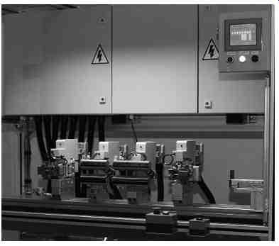
FIG. 8 Cable assembly machine.
6.1 Part Handling
Assemblies often start with one base piece, usually a larger component of some kind. Many products have a frame or housing of some sort that contains other elements. If an assembly processing line is pallet based, this first element is placed onto the pallet either manually by an operator or with an automated device such as a robot or pick-and place mechanism. Larger components may be presented in a palletized form or in a bin. Because of their size and often their method of shipping, these items may be difficult to handle with automation.
Palletized parts are usually easier to load automatically since they can be precisely located within a formed pallet and the pallets can be made in a uniform and stackable size. Automated depalletizers are often built to handle these types of pallet stacks. Filled pallets enter on a conveyor, are destacked and emptied, and a stacker restacks the empties and sends them out on another conveyor. Stacks of pallets are generally handled by forklift.
Not all products can be easily handled by automation. Some basic components may be difficult or expensive to handle because of size or shape. Others may be hard to locate because of shipping and packaging methods. Items that are randomly oriented in bins or must be unwrapped may be more economical to load by hand.
Parts that are easily handled and located may be handled in a number of methods. If parts are presented in an array, such as within a formed or divided pallet or bin, they must be indexed, either by an actuator that can move a gripper to multiple X and Y positions or by a system such as an indexing table. These typically take the form of a pair of servo actuators arranged in a perpendicular manner. If parts are arranged in layers, a servo-operated Z-axis may also be required, otherwise the Z or vertical movement may be a simple pneumatic cylinder with a gripper, magnet, or vacuum cups on the lower end.
Robots are increasingly used for this purpose because of their flexibility.
Intermediate part-handling methods are often used in assembly machines also. Components may be placed onto a dial table or moving fixture so that some kind of work can be performed on the product.
Tooling to accurately locate the part is often mounted to the dial or fixture so that a device, such as a screwdriver or adhesive applicator, can precisely approach a point on the part. This tooling is removable so that it can be easily replaced or modified.
Feeders and conveyors are standard components on many assembly machine and production lines. Feeders usually have queuing and orienting outfeed sections that help locate parts precisely for pickup. Conveyors in assembly machines are often indexing conveyors with fixed stopping points. These may be cleated belt or chain type conveyors or chains with pendants that fixture parts accurately.
Simple methods such as pushers, lifts, pick-and-places, and guides are often used within assembly systems to move and maintain control of parts. A rule of thumb for handling parts is to never lose control, orientation, or containment once you have gained it. Parts may be oriented on a conveyor end to end, be singulated by pushing them perpendicular to their flow, and lined up in magazines or collated into rows. Once they are contained, they should never be placed back into a random arrangement such as a bin unless being rejected or removed.
6.2 Fastening and Joining
An important part of the assembly process is attaching parts and components to each other. After components of a product have been brought into close proximity and have been located accurately, one or both components are picked up or guided into contact. Parts may be connected using fasteners, adhesives, or using various welding methods.
Fasteners are often delivered from fairly standardized systems.
Vibratory feeders are a common method of singulating and orienting screws, bolts, and rivets. Generally, fasteners are fed into a tool, such as a nut or screwdriver, by blowing oriented fasteners up a tube and into an intermediate escapement or buffering section.
Queued fasteners are then brought individually to the tip or receiver of the driver and the fastener is installed either by an operator or automatically. Threaded or tapped holes are generally formed into the base workpiece, usually the larger of the two items being connected.
Most fastener systems are manufactured by OEMs who specialize in this type of equipment. A controller is generally attached to the spindle remotely. The drive mechanism is usually electrical so that torque can be accurately sensed and controlled. Controllers are easily integrated into control systems with digital I/O and communications interfacing to the main control system. Torque and screwdrivers almost always need to collect torque and angle (number of rotations)
information for validation. Fastener systems are often operated manually because of the possible inconsistency of hole locations and angles. There is always the possibility of cross threading and the necessity of reversing the screw or bolt and removing it. Fasteners also may have flaws that require intervention by an operator. Automated fastener systems can be a major cause of machine downtime in assembly systems both in the feed system and the insertion.
Adhesive applicators use cold, air cured, or hot-melt systems to glue parts together. Like fastener systems, adhesive applicators and systems are usually made by OEMs with expertise in this field. Glues and adhesives are usually pumped from a reservoir to an application head. Cold adhesive systems are closed systems that prevent exposure of the adhesive to air until the glue is applied. For cold gluing applications, the glue may be applied using contact or noncontact methods. The distribution for cold systems may use a centralized tank with pipes to application heads or open-wheel pots, bulk containers with gravity feed or pumps through a siphon, or air operated piston or diaphragm pumps. Pressurized tanks are another simple way to distribute adhesives.
Cold adhesives are generally acidic. Stainless steel piping is generally the best choice for the distribution system. Fiber-reinforced engineered plastics and PVC piping are sometimes used but must be protected from temperature extremes and physical abuse. After adhesive has been distributed to a point near the applicator, plastic tubing and noncorrosive synthetic materials are used to bring the adhesive to the applicator. Pressure regulators are usually placed between the pumping system and dispensing guns. Manual regulators can be used if application time and/or line speed are constant; automatic regulators may be required if pressures need to vary by product.
Applicators may be pneumatically or electrically operated. A tapered needle with a ball in a nozzle seat is moved to allow adhesive to flow. Electric guns integrate the solenoid into the applicator with the needle body located inside the solenoid coil. This allows the gun to respond more quickly than a pneumatic valve, allowing more control of the amount applied. The dispensing gun may spray the glue through a nozzle or pattern plate, apply a bead, or extrude adhesive through a slot. Slot dies are used to provide an even coverage and control edge position. They are often used in moving web applications.
Spray guns and bead extrusion are both noncontact methods of application where the nozzle does not contact the part or substrate.
Pattern plate and slot dies are both contact methods of application.
Hot-melt systems use a melter to bring a thermoplastic adhesive to a liquid state. Adhesives are loaded into a reservoir in pellet, block, or slat form and heated. A pump is then used to carry the adhesive through a heated hose to the valve, gun, or manifold, commonly known as the adhesive dispenser. Hot-melt systems are commonly used for packaging applications such as carton or case sealing and tray forming.
Both cold adhesive and hot-melt systems may be used in an automated or manual process. Automated application of adhesive may also use heads that apply small dots of adhesive before pressing parts together. Adhesive systems and applicators must be cleaned often and require periodic maintenance.
Many assembly machines and production lines use a combination of automated and manual processes for joining parts. The decision on which method to use may be based on cost or the difficulty of accessing and handling certain products. Robots may be used in some adhesive applications but are usually not cost-effective.
Other methods of joining components include ultrasonic welding of plastic components and welding of metals. Ultrasonic welding uses high-frequency vibrations to melt plastics together. Parts are placed in a fixed nest called the anvil and an acoustic vibration is transmitted through a metal horn, or sonotrode. Vibrations are generated using a piezoelectric transducer known as an ultrasonic stack. The stack contains a converter that converts an electrical signal into mechanical vibration, a booster that modifies the amplitude of the vibrations, and the horn that applies the vibrations to the part.
The stack is tuned to resonate at a specific frequency, usually 20 to 40 kHz. The two parts are pressed together and an ultrasonic generator delivers a high-powered AC signal to the stack for an appropriate period of time.
Metal welding is generally done robotically in assembly machines.
FIG. 9 shows robotic welding of a metal tube. There are several methods of welding, but the most commonly used in automated applications are metal inert gas (MIG) or wire welding and laser or electron beam welding. MIG welding uses a wire feed as an electrode.
An inert or semi-inert gas mixture is used to protect the weld from oxidization and contamination. The gas also acts as a shield to prevent porosity in the weld; porosity reduces the strength of the weld and may cause a pressurized vessel to leak. This method is sometimes called gas metal arc welding (GMAW). A related process called flux cored arc welding (FCAW) uses a steel wire surrounding a powder fill material. This wire is more expensive than solid wire but allows for higher speed and penetrates deeper into the metal being welded.
Shielded metal arc welding (SMAW) is also called stick welding.
It is also sometimes called manual metal arc welding (MMA) since it is not used in automated applications. Electric current is passed between a metal rod coated with flux and the workpiece. The flux produces a CO2 gas that protects the weld area from oxidation. The metal rod acts as an electrode and is consumed during the operation.
Stick welding is often used when deeper weld penetration is required than wire welding.
Plasma arc welding uses a tungsten electrode and a plasma gas to make an electrical arc. It is often used when welding stainless steel.
A variation of this is plasma cutting, which uses air to blow the melted steel out of the workpiece separating it.
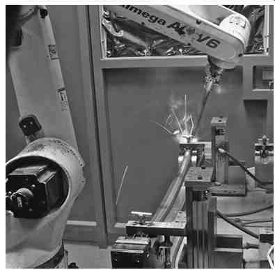
FIG. 9 Robotic welding. (Mills Products.)
6.3 Other Assembly Operations
Many of the operations and processes discussed in the previous sections are also used during the assembly operation. Converting operations, such as pressing or punching, are often performed as long as the residue material can be easily removed. Lubrication of mechanical assemblies and mechanisms is also often done before parts are sealed.
Machining and chip-producing processes are usually performed on parts before they begin the assembly process, but there are exceptions. Inspection of parts following critical processes is also common. This may be a simple part presence check using discrete sensors or separate systems, such as leak testers or machine vision.
Adhesive application is often checked using ultraviolet sensors that look for dyes mixed into the adhesive. Dimensional checks are performed with LVDTs or other analog devices. Check weighing may be done on parts that are in transit or in stations where a part is set on a scale. Failed parts are either removed from the line as rejects or marked/identified for later removal. Parts that are indexed through the line can be tracked either through shift registers in the software or through tracking devices such as bar codes or RFID tags.
Marking and labeling are also common procedures in the assembly process. Adhesive labels, direct printing, and pin stamping are methods often used to imprint alphanumeric characters or bar codes onto products before being packaged.
7. Inspection and Test Machines
Inspection and gauging machinery is often built as a stand-alone unit separate from the assembly process. After completion of an assembly process, the final product may be inspected for quality, tested for function or gauged dimensionally. Many of the individual components of an assembly may have been checked during the assembly process also, but final testing is common for many complex products.
7.1 Gauging and Measurement
There are various ways of checking the physical dimensions of parts.
Tooling can be used to ensure that parts fit where they are designed to. An example is placing posts in a fixture where bolt holes are located on a part. Discrete sensors such as photo-eyes and proximity switches can be used to detect the absence, presence, or location of features on an assembled part. Some manual assembly stations are outfitted with these types of "Pokayoke" checks built in.
FIG. 10 shows a manual 6 LVDT gauging station for automotive parts. LVDTs often have pneumatic actuators that can extend to measure the position of parts relative to the fixture or to each other. This is not always desirable since tooling must contact the part, so machine vision and optical sensors are often preferred.
7.2 Leak and Flow Testing
Products often need to be tested to ensure that they do not leak or that airflow is within prescribed limits. Seals, filters, and gaskets may be part of the assembly being tested. In addition to ensuring their presence during the assembly process, leak or flow testing ensures that they are installed and are operating correctly.
Systems may be as simple as a few valves, some pipe or hose, and a simple pressure transducer. If the purpose is simply to detect gross leaks, detailed validation procedures and calibration to a standard may not be required.
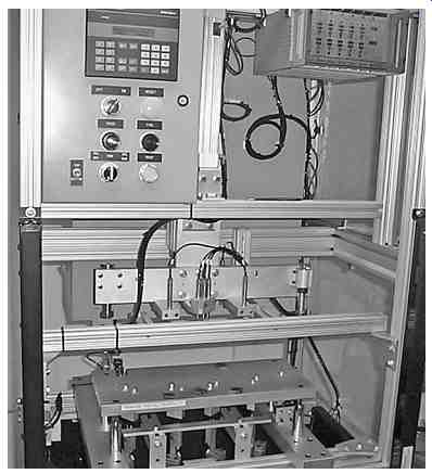
FIG. 10 LVDT gauging. (Nalle Automation Systems.)
When performing tests that require more precision and a validation procedure, it is usually necessary to purchase a packaged system. As with many of the other special-purpose systems discussed here, these systems are usually manufactured by companies that specialize in the field rather than custom machine builders.
Purchased systems such as this have a lot in common, regardless of the manufacturer. The system is plumbed with various valves into an analog pressure transducer. There is an onboard controller with I/O connections for triggering and results, generally 24VDC. There are various communication ports for exchanging information with a PLC or computer as well as a separate programming port and usually a printer port also. These ports may be assignable as to communication protocols. Ethernet/IP, RS232, or open protocols such as DeviceNet or Profibus are common. The RS232 or Ethernet ports generally transmit a configurable string containing test data, time/date, and selected program information. This allows the parsing of the string(s) for the data that the user requires for archiving and display.
Fixturing the tested device usually involves some kind of rubber seal. This may be a solid surface that the product is pressed against or an inflatable bladder that is inserted into a round hole. Regardless of the type of sealing, the process usually involves movement of the part or tooling (or both), which brings the aspect of safety, that is, light curtains or physical guarding, into the picture. FIG. 11 shows a manually loaded leak tester for automotive parts.
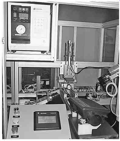
FIG. 11 Leak tester. (Nalle Automation Systems.)
The interface generally allows the test parameters to be set by program number. Fill time, stabilize time, test time, and pass or fail criteria are settable within the interface. Alternatively, these can be externally controlled by means of I/O. A special mode for calibration allows the user to place a calibrated orifice into the flow circuit to test to a known standard. This can be automated for a periodic check.
7.3 Other Testing Methods
Products are often functionally tested by moving components and checking torque values, measuring electrical characteristics such as resistance or current flow, or applying power to a device and operating it. Many of these operations are often done at the end of an assembly line within a system, but "Test Benches" are often designed as a standalone unit to perform these checks.
Solid items are sometimes examined using ultrasonic testers or X-ray testers to locate internal cracks or flaws. Ultrasonic testing is often done in a water bath, so pumps and plumbing as well as material handling may be part of the machine or system. Safety and guarding are also important to ensure personnel are not exposed to harmful effects.
There are many different kinds of specialty devices, such as eddy current testers, which are used to check threading on the inside of tapped holes; ion source leak testing, which determines the size of tiny holes in materials; and various material testing systems for hardness or chemical composition. Some tests may be destructive, rendering the product unusable after testing. These types of test are usually done on a sampling basis.
Prev. | Next
Home top
of page