CHECKING THE ELECTRICAL COMPONENTS
Even though the machine is operable, the electrical components should be checked for worn or frayed cords, broken plugs, etc. The worn parts should be replaced. Check the motor brushes and replace them if necessary. Access to the motor brushes may be gained in one of a variety of methods:
• On some motors, the brushes are located under screw caps (Fig. 2-11). They are generally found in the end of the motor housing opposite the pulley, with the two caps 180 degrees from each other.
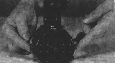
Fig. 2-11: Fingers point to caps covering motor brushes.
• On some motors, the brushes will be found by removing small covers (two in all) at the end of the motor housing (Fig. 2-12). They are generally found opposite the pulley end of the motor.
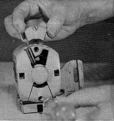
Fig. 2-12. The motor brushes on the Singer Model 319W motor are made
accessible by removing covers on the end of the motor opposite the pulley.
• On some motors, the brushes will be found by removing the entire motor housing (Fig. 2-13).
To assure the correct replacement brush, take the model number of your sewing machine and the information on the name plate of the motor to your sewing machine service center, or write to the appropriate manufacturer or distributor.
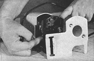
Fig. 2-13. On the Singer Model 248, the motor brushes are made accessible
by removing the entire motor housing.
ADJUSTING THE DRIVE BELT TENSION
The drive belt tension is about right if you can depress the belt about 3/16 inch (5mm) with your finger and you experience no starting or running problems. The tension can be adjusted by loosening the motor mount bracket bolt and moving the motor up or down to get the correct tension on the belt, then tightening the motor bracket bolt (Fig. 2-14). In case the belt is too long to make the adjustment by moving the motor, you might be able to effect a temporary repair by cutting the belt, removing a small section from it and splicing it back together by punching holes (from the under side of the belt) in the ends and abutting them and securing them with a piece of wire or a leather throng laced through the holes.
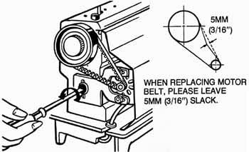
Fig. 2-14. This is how to adjust the tension of the motor drive belt
on the New Home Model 545. A correctly tensioned d belt creates a more
efficiently operating machine.
CLEANING AND OILING THE MACHINE THE FIRST TIME
Oiling a sewing machine, even in the absence of specific instructions isn't a mysterious or complex procedure, providing you understand some basic principles. First of all, you can’t injure a metal bearing point (a point where there is friction between metal moving parts) by oiling it with the proper oil, although over oiling may result in a build-up of oily residue that will attract dust. Secondly, any parts that are not metal, such as neoprene or nylon gears or belts, or rubber or fabric belts or other parts, should not be oiled. Grease should be applied only to metal gears.
At the outset, assume that any machine that has not been used for a while should be cleaned and oiled. To do this, first equip yourself with the following:
• benzene or pure kerosene in a clean oil squirt can.
• sewing machine oil in a squirt container.
• sewing machine gear lubricant (applicable only if your machine has gears).
• an aerosol can of silicone lubricant (not oil).
• lint-free rags.
• a small stiff-bristled brush and a small soft-bristled brush (such as a ½ inch paint brush), both of good quality.
Then oil the motor with two drops of oil (applicable only if the motor is equipped with oil holes). Remove the face plate to expose the needle bar, presser bar, linkages, etc.
You’ll also need to remove the throat plate and the needle plate. If the needle plate is held down with screws, you should use a screwdriver with a 12 inch or 14 inch blade, so that in working around the top arm of the machine, the screwdriver blade can be inserted vertically in the screw slots.
Remove the top cover from the upper arm of the machine, which will usually be held on by two visible screws (Fig. 2-15). This is applicable only to zig-zag machines.
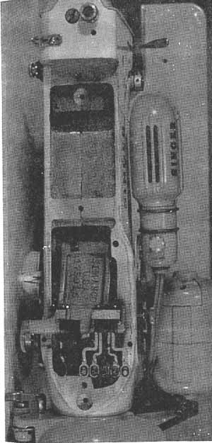
Remove the bobbin and bobbin case. In the front or side- loading machine, the bobbin and bobbin case come out together. In the top-loading or drop-in machine, the bobbin case is removed in an extra step, generally by swinging a spring clip sidewise and lifting upward on the bobbin case.
Gain access to the lower mechanism of the machine:
• swinging the machine up and back, if it's in a console or portable cabinet.
• removing the bottom cover, which is usually held on with one wing nut, if the machine isn't in a cabinet.
• removing the free-arm cover, in the case of a free-arm machine.
With most of the mechanisms accessible, you can brush away all the loose surface lint and dirt with the soft brush, being sure that none of the soft bristles breaks off and lodges in any of the mechanisms. The, use the stiff-bristled brush to work into close areas, especially around the feed dogs and the bobbin shuttle. To proceed with the cleaning and oiling, you can assume that all bearing points and rotating parts need offing. Before oiling them, they should be flushed with the kerosene or benzene. Avoid getting either the oil or the cleaning agent on any gears, on the timing belt or drive belt, or on any other non-metallic parts.
Squirt ample cleaning agent in all the oil holes; on the levers, around the points where the needle bar and presser bar go through the machine housing; around the levers and mechanisms behind the face plate; in all bearing points in the top arm of the machine (some of these points may be supplied by oil holes through the top cover that you removed, but with this cover removed, you will have easier access to these oiling points); and around the shuttle. Then raise the bed of the machine (in the case of a free-arm machine, remove the free-arm cover) and squirt the cleaner in all bearing and rotating parts that are not supplied by oil holes through the bed of the machine.
With the presser foot raised, and preferably with the needle removed, run the machine at high speeds for a few seconds to flush out dirt, lint and old oil residue.
Let the machine stand for five minutes, then wipe away all the excess cleaning agent with a lint-free rag. Examine the machine for cleanliness, and if necessary, work at stubborn areas with the stiff brush. Repeat the flushing procedure with these areas.
Proceed with oiling, assuming that from now on it will be a routing maintenance chore. Periodic oilings are better than using a lot of oil at one time. Squirt two drops of oil in each oil hole and bearing point that you flushed with the cleaner, except those holes that supply the main bearings of the main shaft, in which you should squirt three drops of oil. Put one drop of oil in the shuttle race.
Lightly lubricate all the gears with the gear lubricant. Some gears will be exposed. Others might be enclosed in a gear box, in which case you will have to remove a cover to gain access to the gears. If the gears seem to be adequately lubricated with old grease, wipe away part of the old grease and replace it with the new grease.
Using a flashlight for visibility, spray the silicone lubricant around rollers and other moving parts in the vertical arm of the machine. The silicone will not harm rubber or neoprene parts.
Run the machine at moderate to high speed for about 30 seconds. Let it stand for five minutes, then wipe away all the excess oil.
Reassemble all the disassembled parts, replace the covers and thread the machine. It should now be ready for use. Sew a scrap of material to sew off excess oil.
PERIODIC CLEANING AND OILING
The general rules for routine cleaning and oiling of a machine are:
• If the machine is used for about an hour a day, oil it once a week
• If the machine is used for several hours a day, oil it once a day.
• In periodic oilings, one drop of oil at each oiling point is sufficient, except at the main bearings of the main shaft, which require two drops.
• The areas around the feed dogs and shuttle hook should be cleaned and oiled at each routine oiling of the machine. Use a good quality, stiff-bristled brush to clean around the shuttle, as soft bristles tend to break off and lodge in the shuttle mechanism.
• Regardless of whether the machine is used frequently, infrequently or is in disuse for long periods, it should be flushed with benzene or pure kerosene every six months, and the machine, including the gears should be completely lubricated.
• Never use all-purpose or household lubricants on a sewing machine. Buy sewing machine oil and gear lubricant from your sewing service center.
NEEDLES, THREADS AND MATERIALS
If you have read this section in its entirety, you will have learned that there is a definite relationship between the needle/thread/material combination that's used and the kinds of sewing problems that you might experience. Inasmuch as faulty stitches, breaking thread, etc., may often appear to be the symptoms of a malfunctioning machine, it's important to understand the basic principles of this relationship.
Selecting Needles
In selecting a needle, there is a distinction to be made between needle type and needle size.
Needle Type. The words type and system are used inter changeably to designate needles that can be used with certain brands and models of machines, so that some kind of standardization can be achieved in fitting needles to the hundreds of sewing machines that are to be found on the market. Among the different needle systems are the System 287, which is a round-shanked needle; the System 130R or 130B, which may be either a round or flat-shanked needle with a clearance cut; and the European System 705, which is also called the U.S.A. Type 15X1. It is by far the most widely used type in the U.S. (Table 2-1). However, since an in-depth discussion of needle systems isn't within the scope of this guide, the best way that you can be assured of getting the correct needle type for your machine is to provide your supplier with the brand and model number of your machine.
Needle Size. The size of the needle that you select should have a definite relationship to the thread being used, which is determined by the material being sewn. Most sewing machine owners’ manuals, as well as the packets that needles are supplied in, contain charts (Table 2-2) with information regarding the needle! thread/material combination to be used.
Specialized Needles. With the advent of polyester and double-knit materials, special needles have been developed which are usually recommended by sewing machine manufacturers by brand name. One such special needle is the ball point needle. It pushes the fibers apart, rather than piercing the material.
Selecting Threads
Always buy the best quality thread that you can find. Since it will be almost impossible for you to judge thread quality by its appearance, you will have to depend on brand names to guide you in your choice. Sewing machine dealers generally stock the more reliable thread brands, since they understand that better results can be obtained with their sewing machines if quality threads are used.
Apart from quality, the factors to consider in selecting thread are the material it's made from and its size. The most common threads to be found on the U.S. market today are cotton threads, silk threads and synthetic threads.
Cotton Threads. Cotton thread may be a plain cotton or mercerized cotton. A mercerized cotton thread is one that has been treated with a caustic soda solution to make it soft and glossy. It resists shrinking when the garment is washed. As a very general rule, mercerized cotton, if selected in the proper size is suitable for almost any sewing job. It is one of the most trouble-free threads that you can use. However, cotton thread is becoming hard to find because the demand for synthetic threads has increased with the wide preference for synthetic materials, and dealers are reluctant to stock the comparatively slow-selling cotton thread.
Table 2-1. Needle Types.
15x1 (European 705)
All Singers White Rotary Domestic Rotary Kenmore Rotary National N50 Standard
Davis Shari New Home K, LV Adler Bernina 1251 Brother Classic
Meister 102, 302 Elna Necchir2F BV Pfaff 30 Phoenix 250, 350 Vigoreltl |
20 x 1
New Home Vibrator Eldredge Free West 8F. 52F Montgomery Ward Vibrator White Vibrator |
1 x 2
Davis Long |
40F1
New Home Rotary Free West Rotary |
1 x 4
Domestic |
50N1
Eldredge Rotary National Rotary Montgomery Rotary |
130R (European 705H)
Bernina 530, 540 Calanda Pfaff 130, 230 |
16 x 87
Anker Free New Home |
16 x 231 (European 1738)
Belt 401 fleming 117L bortetti 2000 Seamstress Designer New Home Minerva Phoenix 282. 283 Viking |
127 x 1
Wheeler and Wilson |
Silk Threads. Silk thread, especially the A twist, is used, but it has a more limited application that either the cotton, mercerized cotton or synthetic threads.
Synthetic Thread. Nylon and polyester threads are the most commonly used synthetic threads, with polyester being by far the most popular. Nylon thread is occasionally used when an invisible stitch is wanted, but it has a tendency to kink, making it rather difficult to use. The strong preference for polyester threads when sewing polyester materials is based on its strength, and the fact that it has an elasticity that will prevent seams from breaking when the material is stretched. However, even when using polyester thread, the only insurance against broken seams is to use the stretch stitch. This is a variation of the zig-zag stitch, available only with certain machines and zig-zag cams. Or you can use a modification of the stretch stitch, such as a short, narrow zig-zag stitch. This is possible with the standard zig-zag cam. Even a certain sewing technique can be used which allows you to use either a straight or zig-zag stitch.
The most common problems experienced when using polyester threads are missed stitches (failure of the hook to pick up a ioop at every cycle), tensioning problems and the breaking of threads while sewing. As a general rule, these problems can be solved as follows:
• In the case of missed stitches, try using the needles developed especially for stretch fabrics. For example, Brother supplies such a special needle, under the registered trade name Golden Stretch Stitch Needle.
• In the case of tensioning problems, experiment with different settings of the top tension regulator and regulating of the bobbin tensioner. As a general rule, loosening both tensions slightly can be helpful.
• In the case of breaking threads while sewing, the thread may be inferior, the needle eye may be too small or the tension may have to be decreased.
• In any case, if the trouble persists after you have made the adjustments, try switching thread brands until you find one brand that's trouble-free.
Thread sizes. A numbering system is used to designate the size of mercerized cotton thread, with lower numbers representing heavier thread (Table 2-2). A 50 cotton or mercerized cotton is considered a medium thread. It has a wide range of applications. For best results, however, you should follow the guidelines of Table 2-2. In the case of cotton threads, always match the thread size to the needle size. At this writing, there appears to be no numbering system for polyester threads, with one size recommended for all sewing jobs. A 100% polyester thread may be problematic, in as much as it tends to hang up in the eye of the needle. It also presents a surface to the tension regulator in which a build-up of heat, resulting in expansion and erratic tensioning, is possible. These problems can to some extent be avoided by buying a cotton-wrapped polyester thread. Furthermore since there appears to be some relationship between thread price and thread quality, switching to a more expensive thread may solve the problems of breaking and erratic tensioning of polyester threads.
Table 2-2. Needle / Thread/Material Combinations.
SEWING MATERIAL |
NEEDLE Size |
THREAD SIZES |
|
Very thin |
|
9 |
|
Lightweight |
|
11 |
|
Medium |
|
14 |
|
heavy |
|
16 |
|
Very Heavy |
|
18 |
|
Selecting Materials
Any fabric that's available in consumer outlets is suitable to be sewn on consumer machines, and fabrics are necessarily chosen because they are the most suitable for the desired garment, with no considerations regarding the machine. By using the information in Table 2-2 you can match the needle and thread to the fabric. Some fabrics, particularly the synthetics, tend to rather quickly place a deposit of lint around the feed dogs and the shuttle hook. Therefore when sewing these materials, frequent cleaning of these machine areas is doubly important. As noted earlier in this section, some change in the presser foot pressure may be necessary when changing from one fabric to another.
REGULATING THE MACHINE
Throughout these first two sections, we have repeatedly referred to machine adjustments and regulations that the most inexperienced operator can and should make to achieve the best sewing results. These adjustments and regulations affect the mechanisms, either directly or indirectly. But a distinction should be made between those adjustments and regulations which only affect certain sewing applications and those that actually affect the quality of either the stitching or machine performance. For example, an extremely long stitch which can be achieved by regulating the stitch length regulator, may be incorrect for one sewing application, such as normal sewing, but correct for another such as a basting stitch, in which the top tension should also be decreased. This will not affect the quality of the machine performance. An incorrectly regulated top or bobbin tension, on the other hand, often appears to be the result of a malfunctioning machine. This can cause an unnecessary trip to the repair shop.
First and foremost, you should understand that the dials and levers that provide for operator adjustments and regulations are installed on the machines for a purpose. They are movable, and they must occasionally be moved if you are to achieve the best swing results possible.
Stitch Length and Reverse Regulator
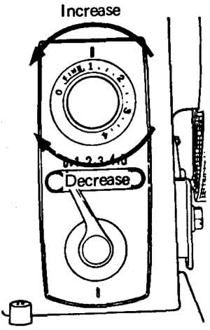
Fig. 2-16 This is the stitch length regulator knob for the Brother
Model 8801.
Different settings of the stitch length regulator simply change the length of the stitches on the straight-stitch machine, or the distance between the points of a zig-zag stitch on a zig-zag machine. This doesn't affect the quality of the machine performance. The stitch length is regulated by turning the stitch length regulator knob (Fig. 2-16). Numerals on the dial represent the stitch length. To increase the stitch length, turn stitch length regulator knob counter-clockwise to larger number on the dial. To decrease the stitch length, turn knob clockwise to smaller number on the dial. The 0 on the dial means that the material isn't fed. The FINE area on the dial is used for making a SATIN STITCH (a close zig-zag stitch). You determine the exact position by observing the feed of the material being sewn.
To sew reverse stitching, push the reverse sewing button as far as it will go and keep it in this position until you wish to sew forward (Fig. 2-17). Reverse stitching is used for reinforcing and finishing all seams.
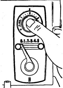
Fig. 2-17. Push the reverse stitch control when YOU want to sew in
reverse with the Brother Model B801 machine.
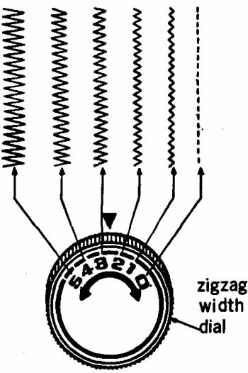
Fig. 2-18. This is a sketch of the zig-zag width regulator on the
New Home Model 545.
Zig-Zag Width Regulator
The zig-zag stitch regulator (Fig. 2-18) works in conjunction with the contour of the particular zig-zag cam to regulate the width of the stitch, from 0mm to about 5mm. It is important to understand that the width of a zig-zag stitch can't be increased beyond certain limits if the cam contours are shallow. Conversely, the width of a zig-zag stitch will be limited by a low setting of the stitch regulator, and will decrease to 0 (straight stitch) as the regulator is moved to 0.
Needle Position Regulator
On most zig-zag machines, a needle position dial or lever allows you to move the entire needle bar to the left, center or right position (Fig. 2-19). If the needle bar is in any position other than CENTER, a zig-zag presser foot and needle plate must be used to keep the needle from striking the foot or plate on its downward stroke, even in straight stitching.
Presser Foot Regulator
For most normal sweeping sewing applications, a normal set ting of the presser foot regulator (Fig. 2-20) is about right. The general rules for adjusting the presser foot pressure are:
• Medium weight materials require normal pressure with a presser bar pressure setting about halfway between the lowest and highest settings of the dial or screw.
• Thin or delicate materials require more presser foot pres sure than heavier materials.
• If the fabric puckers under the presser foot, the pressure should be decreased.
• If the material moves erratically, or seems to slide under the presser foot, the pressure should be increased.
• If the pressure is reduced to zero, the feed dog will have only a slight feeding effect on the fabric, and you will be able to move the material by hand without the action of the feed dog.
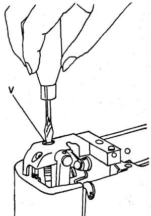
Fig. 2-20.The operator uses a screwdriver to regulate the presser
foot pressure On Pfaff Models 230/332 Automatic.
FEED DOG DROPPING
Many machines have some provision for dropping the feed dog so that the top surface of the feed dog teeth will not contact the material when the machine is running. This feature is used for sewing on buttons, monogramming, darning and embroidering. In the latter three applications, the presser foot pressure is also reduced, so that the material can be moved under the presser foot in a free-hand manner. On most machines, the feed dogs can be dropped by depressing an externally located button. On other machines the adjustment is made by loosening a screw under the bed of the machine (Fig. 2-21).
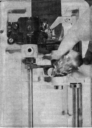
Fig. 2-21 Dropping the feed dogs …
On less expensive machines, disengagement from the feed dogs can be accomplished by installing an accessory needle plate (Fig. 2-22) with a top surface that's raised above the top edge of the feed dog when it's in the highest position. If an older or less expensive machine has neither a drop feed nor an accessory plate to accomplish the same purpose, you may through trial and error, accomplish this purpose by setting the stitch length regulator and presser foot pressure at 0. However, this method does have the disadvantage that the feed dog teeth will contact the material as the feed mechanism goes through its up-and-down cycle, making it difficult to move the material under the presser foot.
If the feed dogs are mistakenly left in the dropped position, the machine will not feed the fabric in normal sewing jobs.
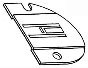
Fig. 2-22. On the Singer Model 248, a relatively new but relatively
inexpensive model, Isolation from the feed dog is accomplished by installing
a special needle plate, with the sewing surface raised above the feed
dog.
PRESSER FEET
As a general rule, a presser foot that's slotted crosswise to provide clearance for zig-zag sewing can be used for most normal sewing jobs. However, certain types of zig-zag presser feet do provide better visibility for certain sewing applications. For example, if you have trouble sewing a straight stitch along a uniform line with a zig-zag machine you should use a straight stitch presser foot. Be sure, however, to set the needle position at CENTER for the appropriate position on your particular machine, with the stitch width dial set at 0.
TENSION REGULATION
While owner’s manuals usually have a considerable amount to say about thread tension regulation, they leave the reader with the impression that once the regulation is set at the recommended average pressure, minimal changes are all that will be required from then on. This may be true as long as you keep the top tension regulator and bobbin tensioner clean, as long as you consistently sew with non-problematic materials and thread and as long as someone else doesn't change the setting of the top tension regulator.
When one of these conditions isn't fulfilled, however, you may experience tensioning problems. It is then that a basic understanding of how much and in what circumstances to change these settings is essential, if you are to get consistently good sewing results. Moreover, poor tensioning often manifests itself as breaking thread, faulty stitching, etc. This can easily be misinterpreted as a faulty mechanism in the machine. The most probable symptoms of poor tensioning are:
• Puckering of the material. This can also be caused by too much presser foot pressure.
• Breaking of the thread while sewing. As a general rule, if the top thread breaks, the top tension is too tight. If the bottom thread breaks, the bobbin tension is too tight. However, other factors that can lead to breaking of threads while sewing (and mislead the operator to believe that the cause is poor tensioning) are cheap polyester threads, usually 100% polyester), which ravel and hang up in either the needle or the bobbin tensioner. Cross layering of the bobbin thread as it's wound on the bobbin can also be the cause of broken threads.
• The point of interlocking of the top and bottom stitches appearing on either the bottom or top of the material (Fig. 2-23), rather than being virtually invisible between the fabrics.
The general rule for correct tensioning is that the top tension should be set halfway between the lowest and highest setting, and the tension spring in the bobbin case should be regulated so that when you let the weight of the bobbin case pull against the thread, no thread will be pulled from the bobbin case. It should take only a slight additional pull to pull the thread from the bobbin case. Once this setting of the bobbin tensioner is established, all subsequent tensioning adjustments should be made at the top tension regulator. Remember, however, that a change of threads in the bobbin may require a change of the bobbin tension.
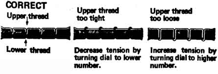
Fig. 2-23. This drawing from the Brother Model B801 operator manual
presents an Inside view of what occurs in stitch interlocking.
Correct Tensioning
To experiment with tensioning, use your favorite quality thread, set the bobbin tension as described and set the top tension at an intermediate setting. At these settings, the stitches should be interlocked between the fabrics. Then, as you turn the top tension too, the interlocking should appear on the bottom of the fabrics, and at 0, noticeable loops should appear on the bottom of the fabrics. When you turn the top tension to the highest setting, the interlocking will begin to appear on the top of the fabrics, until at the highest setting, where there will be loops on top of the fabrics. When changing threads or fabrics, it may be necessary to adjust the top tension setting slightly to one side or the other of the intermediate setting. You may find that if you switch from cotton to polyester threads, the tension will have to be decreased in both the bobbin and top tension regulator.
Regulating the Bobbin Tension
To regulate the tension of the tension spring in the bobbin case, it's best to remove the bobbin case, even in the case of the top-load machine. Examine it carefully under a good light. Some bobbin cases have calibrated dials to indicate higher and lower settings of the tension, and many don't .
Generally, you will see two screws on the tension spring (Fig. 2-24). The screw at the extreme end of the spring is there to hold the spring in place, and the other screw is the tensioning screw. To decrease the bobbin tension, turn the tension spring screw counterclockwise. To increase the tension, turn it clockwise. At the beginning of the procedure, make a mental note of the position of the screw, as determined by the direction of the screw slot. Turn the screw only about V8 turn in the appropriate direction before checking the tension. If synthetic threads are your choice, re member to always use quality, cotton-wrapped polyester, thereby avoiding subsequent changes in the bobbin tension.
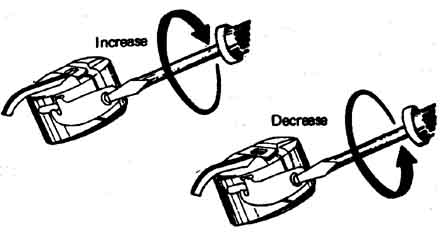 Fig. 2-24. This drawing from the Brother Model B801 operator’s manual
shows how to increase or decrease the bobbin tension. The adjustments
should be slight until the results are noted. Your local repairman might
advise you not to make this adjustment, but sewing perfectionists recognize
the Importance of a variable bobbin tension.
Using the Top Tension Regulator
First and foremost, when threading the machine, you must pass the thread between two tension discs in the top tension regulator assembly. If the machine isn't designed to use a double needle, there will be only two tension discs. But if the machine is designed to use a double needle, there will be three discs. These can be considered as two pair. In the latter case, if you use the optional double needle, and thus two top threads, a thread must be passed between both pairs of discs. If you use a single needle, the single top thread may be passed between either pair of discs.
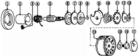
Fig. 2-25. This drawing of the upper tension regulator is taken from
the White Service Manual for oscillating shuttle machines. 1. Base;
2. Tension Barrel; 3. Set screw; 4. Check Spring; 5. Tension Stud; 6.
Tension Disc; 7. Tension Washer; 8. Tension Release Pin; 9. Tension
Presser Tray; 10. Beehive Tension Spring; 11. Nut Tension Dial Stopper;
12. Adjusting Washer; 13. Tension Dali; 14. Spring Washer; 15. Set Screw;
16. Cap.
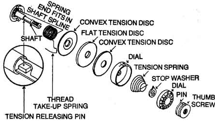
Fig. 2-26. This drawing shows the upper tension regulator disassembled
on the Singer Model 319W. The thread take-up spring, or the thread check
spring, is inserted so that the spring end fits in the appropriate spline
to create a slight tension when the thread pulls the spring counterclockwise.
The appropriate spline might have to be found by experimentation. The
tension releasing pin, shown in the enlarged view, releases the tension
of the tension spring when the presser bar lever is raised. The thread
tension can be correlated to the numbered dial by depressing the numbered
dial while screwing on the thumb screw, and when the actual tension
corresponds to the number on the dial, engaging the thumb screw pin
in the appropriate hole in the numbered dial.
If you suspect missing or misarranged parts in your tension regulator assembly, refer to Figs. 2-25 and 2-26 for representative assemblies. In reassembling the discs, note that each disc has a concave, and a corresponding convex side. In the single needle machine, the discs should be installed with the convex sides adjacent. In the double needle machine, the convex sides of two discs should be adjacent to the flat sides of the center disc.
As part of your ongoing maintenance program, the top tension regulator should occasionally be disassembled and cleaned.
SUMMARY
In this section we have covered machine maintenance and adjustment procedures which should be performed routinely by the operator. With the exception of changing the motor brushes, which is applicable only to machines not under warranty, none of the procedures discussed in this section will void your new machine warranty. However, in the next section, we will discuss internal adjustments and repair procedures which you should undertake only if there is no chance that it will jeopardize your service warranty.
