Nothing of any size will remain standing for long without a foundation— from a hole in the sand dug to support a beach umbrella to the metal supports for a highway sign. Foundations do many things: they keep water out, support gravity loads without settling unduly, resist the “uplift” forces of wind, and hopefully stabilize a structure for a very long time. Even the Leaning Tower of Pisa’s foundation, while clearly not perfect, has helped keep it from falling over.
Foundations have been important to city building for centuries. Most of the world’s earliest metropolises were ports, located adjacent to lakes, rivers, or the sea, and as a result their soil tended to be watery and unstable. Wood piles were used as foundations in these places until the Industrial Revolution, when iron became more widely available.
The earliest skyscraper foundations were thus made of iron, soon to be supplanted by steel. At the time the science of geotechnical engineering was in its infancy. Perhaps not surprisingly, the earliest tall buildings— particularly a number of those built on the soft clay soil of Chicago—settled more than they should have. The Federal Building in Chicago settled so much after its completion in 1880 that it had to be completely destroyed 18 years later.
But foundation technology moved forward quickly as buildings grew taller.
The size and shape of larger loads required foundations to reach farther down into the soil, typically penetrating multiple layers of the earth. In general, the taller a building the deeper its foundation would reach—and the more complex the foundation design and construction process that accompanied it.
Today the amount a skyscraper will settle is carefully calculated and factored into the design of the building. It’s only one aspect of a very complex design process that demands myriad decisions, including what kinds of supports should be used underground (e.g., piles or caissons), what types of material they should be made of (e.g., steel or concrete), how deep they should extend (e.g., to bedrock or not), and how they should be placed underground (driven or bored).
In general, this process is highly scientific, with powerful computers used to model and predict a building’s behavior. However, there is an element of art to it too: it’s said that the world’s best geotechnical engineers can estimate the extent of building settlement fairly accurately on the back of an envelope, given the basic parameters of the soil and the building’s configuration and loads.
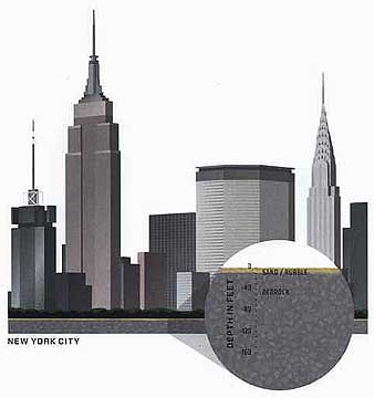
NEW YORK CITY
Soil types and layers vary greatly from city to city. Within cities themselves, soil layers and levels can vary dramatically; in New York, for example, bedrock is much closer to the surface uptown, near Central Park, than it’s in lower Manhattan. And even within the confines of a building site, soil irregularities can require modifications to standard designs; Malaysia’s two Petronas towers were moved 200 feet (60 meters) to take account of an unusually precipitous drop in the bedrock at the point where one set of piles was to be located.
Despite the urban myth that skyscrapers can only be built where bedrock is close to the surface, they can be built just about anywhere. Two of the world’s tallest stand proudly near Chicago’s Lake Michigan—on soft, claylike soil. Two more are founded on the sandy soil of what was once Lake Texcoco in Mexico City and have proven themselves (not once, but three times) to be stronger and more stable than many of their shorter neighbors.
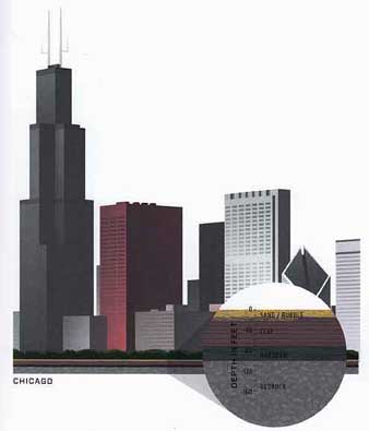
CHICAGO
Test boring --- To design a foundation, geotechnical engineers will prepare a detailed map of the soil beneath a building site. They are particularly interested in the location of different layers of rock or minerals and the extent to which air and water may be present. Several techniques may be used to prepare this map, including seismic measurement, ground-penetrating radar, and test borings.
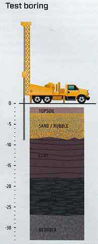
Test borings involve forcing a pipe casing into the earth to remove samples of material across the building site. Samples will be tested for weight, porosity (how much air and water they include), permeability (how fast water moves through them), and consistency. Even bedrock may be accorded different degrees of hardness, and the location of any fracture lines will be noted.
Underpinning:
Skyscrapers are generally constructed in dense urban areas—and often directly up against adjoining buildings. Because digging a new or deeper foundation for a skyscraper will likely disturb the soil underneath adjacent buildings, these neighbors—big or small—will often require underpinning before construction of the foundation can start.
Underpinning counteracts or prevents subsidence of the soil and resulting settlement or collapse of the existing building. It also protects against “heave”— the upward pressure of the soil on a building.
Typically underpinning involves digging below an existing foundation and pouring additional concrete to extend either its width (to better distribute the existing load) or its depth (so that the neighboring building rests on more solid material). A variety of techniques maybe used, including the placement of temporary supports to “jack up” the building as excavation proceeds. Others involve the construction of additional foundation supports and then a choreographed transfer of the existing building from its original foundation to the new one.
Full excavation takes place only after the neighboring structure is fully underpinned.
The process is repeated in a sequenced manner, determined by a structural engineer, to ensure the building’s structure is not damaged.
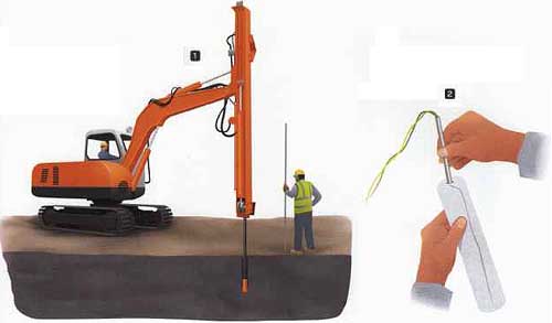
Test borings, surveys, or regulations demonstrate the need for underpinning of buildings adjacent to a building site. The location of utilities must be clearly identified prior to excavation being undertaken.
An excavation pit is dug to allow access to the neighboring building. It must be properly shored and strutted to prevent cave-ins.
The building’s existing foundation is strengthened through expanded concrete footings or by tying it into additional driven piles.
Whistles -- Bedrock conditions often require more than just large excavators and backhoes. Moving the rock requires dislodging it first, generally through some form of blasting. Before any underground rock blasts occur, a series of whistles lets site workers and passersby—as well as workers and residents in nearby buildings—know that a blast is imminent.
In Manhattan, For example, one whistle means three minutes until blasting, two whistles means one minute until blasting, and a series of three whistles signifies an imminent blast. Following a blast, a long whistle will be given as the “all clear” signal.
1. A hole is drilled with a small rock drill or jackhammer anywhere up to 10 feet deep into the rock. This hole will hold the explosives.
2. A blasting cap is inserted into the dynamite. The highly explosive cap will be used to initiate the explosion.
3. The explosive is lowered into the hole. This and any other charges are tamped down and then covered with dirt, sand, or clay.
4. Large steel-mesh mats are placed over the blast hole and surrounding area to contain fragments and concentrate the explosion. Each mat can weigh up to a ton.
5. After a series of safety checks are made and warning whistles are sounded, the “shooter” connects the blasting wires to the blasting box and detonates the charges.
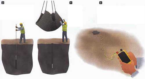
Blasting:
Digging deep in the middle of a city often demands more than a powerful excavator. It may require the blasting of earth well below the surface of a job site, particularly if rock is found at or above the levels that will constitute the foundation. Various forms of dynamite will generally be used to remove it. The placement of dynamite underground is done by drilling a careful pattern of blast holes and then wiring together the explosive charges placed inside them. A “blasting cap,” made of pure nitroglycerine, is located at the end of a cartridge and placed at the bottom of the hole. Dirt or sand is packed in the hole on top of the cartridge and heavy, metal-mesh blasting mats are placed at the surface to protect site workers from any material sent flying by the explosion.
Once the dynamite is set and covered, an electric charge—initiated by a plunger on a remote blasting box—is carried through wires to the individual caps. The resulting explosions are timed to go off in a specific sequence—often seconds, or fractions of a second, apart.
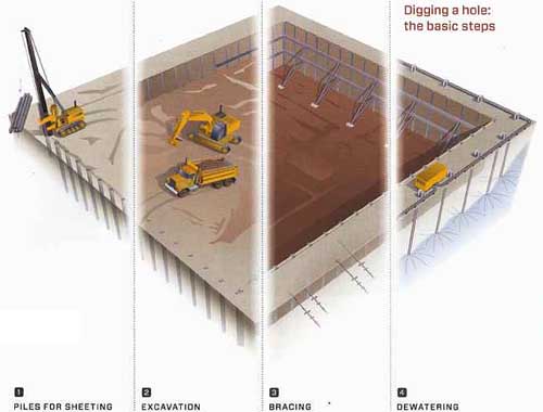
Digging a hole: the basic steps:
1. PILES FOR SHEETING -- A pile driver sinks a continuous perimeter of steel sheet piling into the ground.
2. EXCAVATION -- Excavation proceeds within the area that is surrounded by sheet piling.
3. BRACING -- Bracing, in the form of steel members placed inside the pit or tieback cables extending outward from it, is installed to further protect the integrity of the excavation.
4. DEWATERING -- Depending on the level of the local water table, “dewatering” may be necessary during foundation construction. A variety of well and suction techniques help lower the amount of water flowing into the site.
Sheeting and Bracing:
You don’t need to be an engineer to know that the first step in constructing a foundation is digging a hole. But in the world of tall buildings, the earliest stages of foundation work must happen before excavation begins. Sheeting and bracing must be placed around the perimeter of the site to ensure that the soil around the soon-to-be-dug hole won’t collapse into it during construction (like a hole in the sand at the beach) and that the foundation’s perimeter wall, generally made of reinforced concrete, can be built precisely as designed. A variety of technologies may be used to retain the earth around a hole. Often sheet piles—thick sheets of steel woven together to form a continuous, interlocking barrier—will be driven one at a time into the earth prior to the start of excavation. Alternatively, soldier beams—wide- flange steel sections resembling the letter “H”—may be placed into the earth six to [ feet apart, so that steel sheeting or wood may be inserted between them during excavation.
Once excavation is under way, steel sheeting alone is not enough to resist the pressure of the soil pushing into the newly dug hole. Various bracing methods are typically used to stabilize the sheeting.
Long structural elements maybe placed across an excavation so that loads from the soil on opposite sides of a job site resist each other. Alternatively, bracing may be placed on a diagonal between the sheeting wall and the ground inside the excavation.
“Tiebacks,” also referred to as “cables” or “stays,” are often used to provide additional support. Tiebacks are steel tendons that are drilled into the wall face and anchored well beyond any area of potential soil instability. They exert pressure in the opposite direction of the soil outside the perimeter wall, further supporting the sheeting.
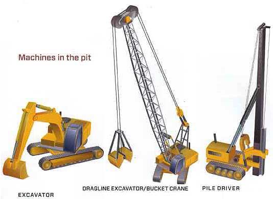
Machines in the pit
EXCAVATOR The workhorse of the pit
DRAGLINE EXCAVATOR/BUCKET CRANE Used to remove soil and rock
PILE DRIVER Used to drive piles for the foundation
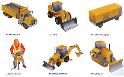
DUMP TRUCK Used for transporting loose dirt, gravel, and rock
LOADER Used to load loose construction debris into trucks
AIR COMPRESSOR Provides high-pressure air to many handheld tools at the site
JACKHAMMER Used for smaller, precision excavating
BACKHOE LOADER Performs the function of an excavator and a loader
BULLDOZER Used to push large quantities of debris
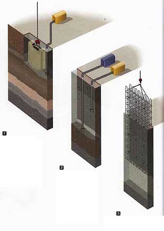
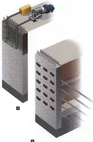
Diaphragm Walls:
From time to time more substantial permanent walls maybe constructed to assist the excavation process. Known as “diaphragm” or “slurry” walls, they assist with earth retention and prevention of water inflow during excavation, and can serve as permanent (though generally not load bearing) basement walls.
The first step in constructing a diaphragm wall is digging a trench around the site. To resist the earth pressure as the trench is dug, it’s filled with a slurrylike mixture (generally made of water and an expansive form of clay) that expands and prevents water or earth from entering the trench. A steel frame composed of reinforcing bars is then inserted into the slurry.
Following insertion of the frame, concrete is pumped into the trench from its bottom. The concrete pushes the slurry upward, allowing it to be easily pumped out from the top of the trench. The concrete then hardens in place around the steel frame to form a permanent wall. Tiebacks may be inserted through it to further offset the weight of the soil pushing inward on the new wall
The World Trade Center’s “bathtub” -- The World Trade Center “bathtub” is perhaps the best-known example of a diaphragm wall. Because of the site’s proximity to the river, the earth was saturated and did not lend itself to simpler excavation and dewatering techniques. A huge slurry trench, four blocks wide by two blocks long, was designed to serve as “the bathtub” to keep the river out of the site. Tiebacks were inserted in the wall prior to site excavation to ensure that the difference in pressure during excavation would not compromise the wall’s integrity. The bathtub remained intact following the destruction of the buildings in 2001, and is now the site of the construction of the 9/11 monument and new office towers.
1. Trenches are dug down to bedrock level. While digging is done, o slurry made of water and an expansive clay called bentonite is piped into the hole.
2. The bentonite slurry material expands along the sides of the trench, blocking the groundwater from seeping into the excavation pit.
3. A steel frame is lowered into the newly dug hole.
4. Concrete is poured into the bottom of the trench. At the same time, the bentonite slurry is pumped out of the top of the trench.
5. Tiebacks are driven through predetermined points in the wall to prevent the diaphragm wall from collapsing inward during construction.
City of fill -- Depending on the size of the planned skyscraper, enormous amounts of material may be excavated from one job site. In the case of the World Trade Center in the 1960s, roughly 1.2 million cubic yards (917,000 cubic meters) of earth and debris was excavated from the 16-acre (6.5 hectare) site to accommodate the complex’s foundation. Instead of trucking or barging this material outside of New York City, it was used as fill to help create 23.5 acres (9.5 hectares) of land alongside the river’s edge just opposite the Trade Center site (most of the other fill came from harbor dredge spoils). Today that fill is known as Battery Park City—and is home to thousands of residents and millions of square feet of commercial office space in addition to supermarkets, schools, museums, yacht marinas, and a highly acclaimed waterfront park.
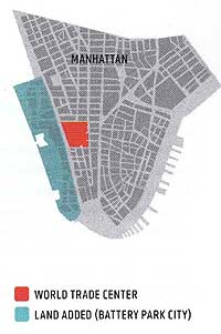
• WORLD TRADE CENTER LAND ADDED ( BATTERY PARK CITY)
The fabulous Baker boys -- There are two of them. They’re both named Baker and both (appropriately) from Chicago, one of the world’s greatest skyscraper cities. And while they’re a generation apart and not in any way related, it’s fair to say that—with the possible exception of Cesar and Rafael Pelli—they have together had more impact on the world of skyscrapers than any other name- connected pair in the business.
Clyde Baker, a geotechnical engineer by profession, knows as much about constructing foundations for tall buildings as almost anyone on the planet. And well he should; at age 80, his years of experience are unmatched. Seven of the 20 tallest buildings in the world were designed to stand on his foundations, and he has been involved as a consultant in countless others. Clyde calls himself “pre-computer,” but he is hardly old school: the innovative foundations that today support the Petronas Towers as well as the new Burj Khalifa in Dubai were designed with his input.
The “other Baker” is Bill, generally recognized as the foremost structural engineer working in skyscraper design today. As a partner at Skidmore, Owings & Merrill (SOM) in Chicago, Bill can trace his lineage back to Fazlur Khan—who held the same job at SOM when he devised his “framed tube” concept that would revolutionize skyscraper design. Baker’s influence may ultimately be just as far- reaching as Khan’s: his concept of the “buttressed core” allowed the Burj Khalifa to reach a full 1,000 feet (305 meters) higher than Taipei 101, the tallest building in the world between 2004 and 2009.
Caissons and Piles:
There are far more words to describe technologies to transfer loads from a building to soil or rock than there are technologies themselves. The words “piers,” “caissons,” and “pila” are most commonly used, though their respective meanings vary from country to country. To confuse matters further, caissons are often referred to as “drilled piles.”
To keep it simple, most foundations can be thought of as comprising either driven or bored piles. Driven piles are prefabricated structural elements driven into the ground. They compress the soil around them in the process, creating friction and thereby increasing their own load-bearing capacity.
Bored piles, often referred to as caissons, are often thread through soft material to reach rock or other bearing material. Typically they are fabricated on-site and sized to fill a predrilled hole in the ground. Temporary casing may be used to protect the hole while it’s being drilled. Subsequently, a reinforcing cage will be placed in the completed hole before concrete is poured around it.
Piles come in many sizes and types and may be made of steel or a mixture of concrete and steel. Their configuration, including their length, is determined by an analysis of the soil in which they will be placed as well as by the physical characteristics of the construction site.
Piles are also differentiated by the way in which they transmit their loads. “End- bearing” piles carry their loads directly to soil or suitable bearing material deep under the building’s foundations; consequently, they are only as strong as the soil or rock that lies at their base. “Friction piles,” also referred to as “cohesion piles,” transfer loads along their entire length through a form of skin friction. They are often driven in groups, to reduce the compression of the soil.
In addition to piles and caissons, many skyscraper foundations feature “mats” or rafts”—flat expanses of reinforced concrete used as building supports on shorter buildings or where rock is shallow. On supertall skyscrapers, these mats are often used in combination with piles or caissons—as a way of knitting them together and providing further stability to the building’s foundation.
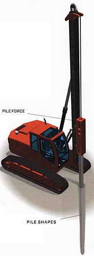
Driven piles -- Driven piles are typically used when the underlying ground condition is granular or rock. Prefabricated piles are often made of pre-stressed, reinforced concrete or steel. The displacement that occurs as the pile is being driven compresses the soil around it, thus increasing both the friction against it and its load-bearing capacity. The length, shape, and material of the pile depend on the type of soil, the need to minimize vibration during construction, and the nature of access to the building site.
PILE SHAPES Reinforced concrete—driven piles will typically be shaped like o noil, but steel piles may take the shape of an X or H cross section or a hollow pipe.
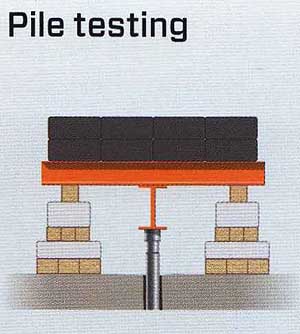
Pile testing -- Through pile testing, it’s possible to check that the piles as designed will be adequate to support the building’s weight before completion. In a Kentledge pile test (shown), reaction weights are stacked on top of a structural grillage that distributes weight over the piles; the applied force versus the displacement of the tested pile is measured.
PILE FORCE: Every one to two seconds, a pile-driver can deliver up to 250 ft-lbs per blow. This is equivalent to dropping 30 to 4 Volkswagen Beetles from a height of seven stories.
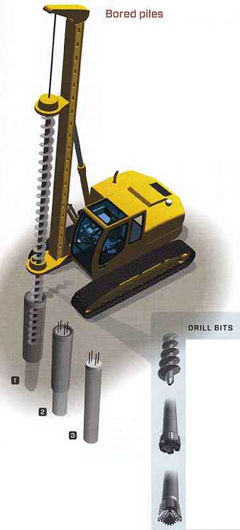
Bored piles -- Bored piles, also referred to as non-displacement piles, drilled piers, or caissons, are generally used in softer or claylike soil conditions. A shaft is drilled by a drill rig, typically relying on pneumatic, hydraulic or diesel power and employing varying types of drill bits. The drilling of the shaft and the installation of the pile, usually consisting of a metal reinforcing cage and cement, are generally vibration-free
BORING A PILE:
1. An auger is inserted into the ground with a drill rig. A steel casing or bentonite mud maybe necessary to support the new hole.
2. When the required boring depth is reached, a reinforcement cage is installed and the pipe is filled with concrete.
3. Finally, the auger and supports are removed.
DRILL BITS:
Hollow-stem augers are used for loose soil, clay, and surface materials.
Farther down the hole, hammer bits are used for soft rock, like calcites, dolomites, limestones, and hard shale; the drill string is rotated along with pneumatic pressure, and nibs on the bit shear the rock.
Rotary drill bits consist of teeth on wheels that turn as the drill string is rotated; these teeth apply a crushing pressure to the rock, breaking it up into small pieces.
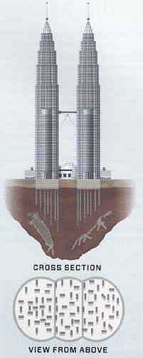
The deepest foundation:
CROSS SECTION
VIEW FROM ABOVE
The foundations of the Petronas Towers are the world’s deepest—extending roughly 500 feet (150 meters) below grade. Because the limestone bedrock below the site slopes sharply, foundation engineers initially designed a hybrid foundation system: one side of the complex would rest on bedrock and the other on concrete columns. But analysis suggested that such a mixed foundation system might settle unevenly—awkward for two buildings connected at the top. So the building was relocated 200 feet (60 meters) east, to an area that could evenly support a thick concrete mat connecting bored piles.
The piles chosen for the foundation were unusual: they were rectangular, not circular, and featured indentation along their sides. Known as “barrette piles,” their novel shape increased friction with the surrounding soil. During their placement, however, the limestone at the base of the piles was found to be unacceptably porous. As a result, reinforcing grout was injected up to 100 feet (30 meters) below the top of the bedrock layer to hold it together permanently.
Earthquakes:
Foundations for skyscrapers are tailor-made and take account of the properties of the soil at a particular site as well as the specific design and weight of the building. Nowhere is this more true than in an earthquake zone, where a tall building is expected to withstand several major seismic events over the course of its life.
The vulnerability of buildings to earthquakes largely relates to their “natural frequency”—the degree and speed at which a building will move back and forth in response to a seismic wave. Buildings vary widely in their natural frequencies due to height, structure, and stiffness. In general, those buildings that happen to move back and forth in sync with a seismic wave will greatly amplify its force upon them—a phenomenon known as “resonance”—and will often be damaged or destroyed in the process.
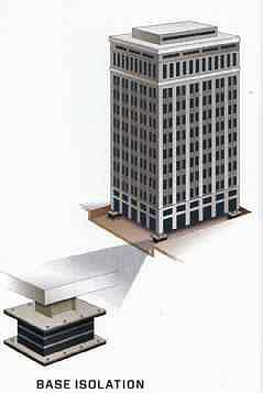
A variety of foundation and structural techniques have been devised to protect buildings from seismic events. In smaller structures, a variety of specialized interconnections, generally referred to as “base isolation techniques,” are used to permit a building to slide around on its foundation—thus minimizing the transfer of seismic energy to the structure above. But because tall buildings can suffer “uplift” problems (water from below or lateral forces can push a building upward), a stronger connection between tower and foundation is required.
Foundation technologies used to stabilize tall buildings in areas of frequent seismic activity include reinforced concrete mats (also called “rafts”) that sit under the structure and connect the piles or caissons drilled deep down into the earth. These mats can be as large as six feet (1.8 meters) thick and the piles and caissons they connect will generally be long—extending down to stable, load-bearing soil.
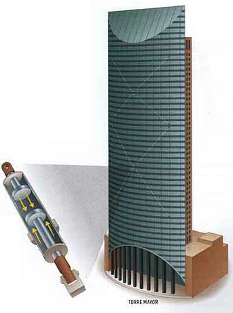
Above the ground, other technologies are often employed to minimize the building’s movement. Fluid, viscous dampers—a form of building shock absorber—are increasingly used within the steel structure of tall buildings to dissipate seismic energy. On the Torre Mayor in Mexico City, For example, these dampers can be seen running alongside the external bracing (another feature commonly used to minimize a building’s lateral movement) on the building’s perimeter.
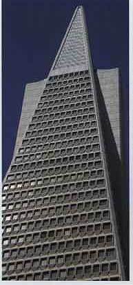
The pyramid’s secrets -- No area of the United States is as earthquake-prone as California, and San Francisco—located atop the San Andreas and Hayward faults—is particularly prone to them. As a result, the city’s skyscrapers are built to resist earthquakes.
The Transamerica Pyramid, perhaps the world’s most recognizable modern pyramid, is a good example. Located atop land that at one time was part of San Francisco Bay, it required a particularly strong and deep foundation. To support its 48 floors, the building’s concrete mat foundation—comprised of some 16,000 cubic yards (12,200 cubic meters) of concrete and 300 miles (483 kilometers) of steel reinforcing rods—was sunk 52 feet (16 meters) into the earth and designed to move with the tremors.
Above ground, its quartz cladding was designed with clearance between its panels to allow for movement of the skin during a seismic event. To provide additional support for horizontal and vertical loads, a unique horizontal truss system was installed above the building’s first floor.
BASE ISOLATION--While typically not used in toll skyscrapers, abase-isolation system is one of the most commonly used methods of seismic protection. The principle of base isolation involves decoupling the building from ground motion during an earthquake by mounting rubber bearings between the building and its foundation. Pasadena and San Francisco city halls and several of Salt Lake City’s municipal buildings have been retrofitted with base-isolation systems.
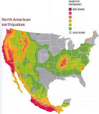
North American earthquakes:
As shown on the map, the western half of North America is prone to larger earthquakes, due to several major fault lines that snake through the Pacific Northwest, California, and Mexico. A number of techniques are used to mitigate their impact on the built environment.
Resonance -- Like striking a tuning fork, an earthquake’s unique energy will cause buildings of certain heights to experience extreme motion, or “resonance.” This typically occurs when the frequency of the building’s vibration (or “natural frequency”) matches the vibration of the earthquake. Sixty percent of the buildings damaged in Mexico City’s devastating 1985 earthquake were between six and 15 stories; those taller and shorter were less likely to experience damage.
VISCOUS DAMPERS -- Viscous dampers, a form of structural shock absorber, can reduce the movement of structures in an earthquake by as much as half. They are typically placed in a diagonal or chevron configuration between structural columns of a building. Buildings relying on these dampers include Los Angeles’ city hall, the San Francisco Civic Center, the Tokyo Rinkai Hospital, and the Torre Mayor in Mexico City.
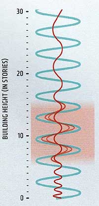
EARTHQUAKE VIBRATION
BUILDING VIBRATION
SEVERITY OF EARTHQUAKES: MOST SEVERE - LEAST SEVERE