Streams and Rivers Provide Energy Free for the Taking
The use of waterwheels to free human beings from heavy labor is almost as ancient as the use of draft animals. The earliest applications of such wheels were to raise water from wells and to turn millstones to grind grain. Later, waterwheels were adapted to provide power for other processes to which a slow, ponderous, unceasing rotary motion was suited. In early America, textile factories and sawmills were generally built on riverbanks to take advantage of waterpower.
---
--------------
Making your own stove
-------

Small wood stove can be made from a 15-gal.
Closed-head heavy gauge grease drum after cleaning drum of any residue of grease.
Tolerances need not be precise. One weld and some furnace cement to hold stovepipe flange to stove top are needed. All other parts bolt on. Cut rectangular openings for fuel loading and ash removal; then cut doors from sheet metal to overlap the openings 1/2 in. all around.
-----------
With the advent of steam power in the 19th century, the massive, wooden waterwheel became obsolete, and water did not again compete as a power source until the invention of the high-speed turbine for generating electricity. This development not only led to huge hydroelectric installations but also made small, private hydropower installations possible.
A personal hydroelectric power source has the potential to sustain every household energy need and provide an unexcelled level of independence. Having enough water flow is less a problem than one might imagine, particularly in hilly areas where hundreds of thousands of potential hydroelectric sites remain untapped. With a drop of 50 feet from water source to turbine, for example, a brook small enough for a child to jump across can provide enough power for a single-family dwelling. However, bear in mind that the smaller the installation, the higher will be the construction cost for each kilowatt generated. Scaled against the cost of power from a public utility, it may be 10 to 20 years before a small installation pays back its initial expense, though rising fuel costs may substantially shorten the payback period.
Traditional Waterwheels

------- Individuality and variety marked the waterwheels of the past. Their diameters ranged from 3 ft. to 20 ft., and they incorporated every conceivable water-flow scheme. The most efficient type was the overshot wheel shown above, but if the water source was not high enough, a breast wheel or undershot wheel was employed. Of low efficiency, but simplest to build because it used no gears, was the tub wheel. A typical large wheel made 10 to 20 revolutions per minute; with wooden gearing this could be stepped up to 10 times the rate. A number of traditional waterwheels are still in operation in America, turning out the stone ground meal so highly prized by home bakers.

-------- Old-fashioned gristmills could grind 5 to 10 bushels of grain an hour. The miller poured the grain into a hopper from which it trickled down through the eye of the upper millstone onto a bed stone. As the 1/2-ton upper stone rumbled over the bed stone, it scraped off husks and pulverized the grain. The husks were then separated with a sieve, leaving flour.
Modern Waterpower Systems
Waterpower achieves its greatest usefulness when it is converted into electricity. Lighting fixtures, heating systems, small appliances, cooking ranges, and machinery of all sorts are some of the common applications. The conversion is made possible by electrical generators that transform rotary motion into electric current.
Though not originally designed for the purpose, old- fashioned waterwheels can actually be used to run generators, but not without overcoming a major obstacle: electrical generators do not operate efficiently except at high speeds, on the order of 1,500 revolutions per minute.
To reach these speeds, a large step-up in the waterwheel's rate of rotation is required, somewhere in the vicinity of 100 to 1. Wooden gears simply will not work-friction alone would destroy them. Instead, rugged, well-made gears or pulleys are required that are not only highly efficient but also capable of handling the huge forces present in the shaft of a waterwheel. Heavy-duty tractor transmissions have been adapted for the purpose and can provide several years of service. The design and construction of a system that will last 20 years or more calls for a high level of mechanical ingenuity plus persistence and luck in finding the appropriate used or abandoned equipment.
Gearing problems can be circumvented by using a turbine instead of a waterwheel. Turbines are devices that convert water flow directly into high-speed turning motion.
Little in the way of supplementary gearing is needed to achieve generator speeds. In addition, turbines are much smaller than waterwheels of the same power output, hardly larger than the generators with which they are coupled.
Turbines run with a high-pitched whine-not as soothing as the rumble and splash of the old mill wheel-and some are subject to cavitation (wear caused by air bubbles).

------ Pelton turbines operate best with heads of 50 ft. or more.
The high-velocity jet of water that results from such heads spins the bladed runner up to generator speed without the need of additional gearing. Pelton runners can be any size from 12-ft. diameters for megawatt installations down to 4- to 18-in. diameters for home installations. Very little flow is required to run a small Pelton turbine, in some cases no more than the water issuing from a modest spring. The need for a high head, how ever, restricts installations to hilly or mountainous locations. Also, springs tend to dry up during some parts of the year and freeze up during other parts, so care must be taken to select a water source that will provide year-round power. A recent improvement in impulse turbines is to orient the jet at an angle to the blades, as in Turgo turbines. These units are smaller and faster than Peltons.
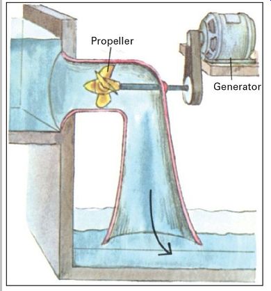
---------- Propeller turbines are most effective at relatively low heads of from 3 ft. to 30 ft. The propeller is completely submerged and is impelled more by the dead weight of the water than by the water's velocity. In high-head installations, propeller turbines suffer wear from cavitation.
In addition, they work well only over a narrow range of speeds, so care is required to match the size of the turbine to the available stream flow . For example, when flow drops to 50 percent of a propeller turbine's optimum, the power output will drop by about 75 percent, and when the flow drops to 30 percent, the output becomes nil. To overcome this limitation, some large hydroelectric installations use several turbines in tandem, shutting down one or more whenever the flow lessens. Others employ Kaplan turbines, which have automatically adjustable blades that compensate for flow changes.

---------- Cross-flow turbines work well when the head is greater than 3 ft. Water from a rectangular orifice passes through a barrel-shaped runner in such a way that the water strikes the ring of blades on the runner two times. This turbine is a relative new comer; it has not yet been built in megawatt sizes but show s a great deal of promise for use in small installations. Moreover, it is simple enough for a person with a home machine shop to make; yet it can match the performance of the other turbines show n, whose fabrication requires a high level of technology. It works well over a wide range of water flow , is relatively free from problems caused by silt and trash, and is not affected by cavitation. To improve efficiency, the rectangular orifice can be partitioned and parts of it closed off during periods of low flow some step-up gearing may be needed for optimum generator speed.

----------- Francis turbines can be used over a wide range of heads 4 ft. and more. As with a propeller turbine, the runner is immersed in the head water, which is guided onto the blades of the runner by a ring of adjustable vanes. The Francis turbine is highly efficient at its optimum flow but easily damaged by grit and cavitation. It is frequently used in large hydroelectric stations and is relatively expensive. As with propeller turbines and other interior flooded turbines, a draft tube beneath the unit with its bottom rim immersed at all times in the tail water (the water flowing out of the power station) is a valuable adjunct: as water drops from the turbine runner down the draft tube, it sucks more water down with it, adding to the effective head of the system. This added head can be of substantial importance whenever the overall head of the remainder of the installation is small.
Before you buy a turbine, you should measure the characteristics of your stream, particularly its head, so you can match the turbine to them. ("Head" is the vertical drop the water makes from the point where it is diverted from the stream to the point at which it reaches the power- generating equipment.) Pelton wheels, for example, perform best under high head conditions; propeller turbines, the reverse. "Flow"-the volume of water carried by the stream past a stationary point each second-is also a factor in turbine design.
Finding Out How Much Your Stream Can Do
To determine the amount of power available in a stream, it is necessary to measure the water flow and make calculations from these measurements. This is not a hard job, since a rough estimate is usually all that you will require. Generally, wide seasonal variations in flow put a limit on the degree of precision that makes sense when measuring a stream.
Changes on the order of 100 to 1 in the volume of water carried by a stream are not uncommon from one part of the year to another. In the Southwest, large rivers as well as smaller streams often dry up completely for long periods of time.
The key information that your measurements should provide is whether or not a stream will yield enough kilowatts of electricity to make its development worthwhile.
You will also want to get an idea of how large the equipment has to be to generate these kilowatts and what type of installation should be used.
A rough estimate, however, may fail to provide sufficient precise data to determine how the installation should be constructed or what specifications the turbine and generator should have. For greater precision professional surveying instruments may be needed; but before involving yourself at this level of complexity, consult the turbine supplier with whom you expect to do business. He should know the degree of accuracy required.
A stream should be measured several times during the year so that its overall potential can be estimated and the power-generating equipment tailored to the variations in flow. The measurements will have value even when the flow is so large that only a small fraction will satisfy your power needs. It is particularly important to measure a stream near its low point during the year. Also, potential flood level should be ascertained if equipment is to be installed near enough to the stream so that it could be destroyed by a flood. When a dam is to be constructed, knowledge of flood potential is crucial.
If you are not familiar with your stream's annual ups and downs just by living near it, contact the nearest U.S.
Geological Survey--Water Resources Office (a branch of the Interior Department) for information on water runoff in your area. The information is free and likely to include rainfall and river flow data going back many years. If a stream is too small to have been directly measured by the office, a knowledge of local water runoff will help you form a profile of its behavior.
What You Must Measure
To find out how much power a stream can deliver, you must know three key measurements: the stream's head, its velocity, and its cross-sectional area.
When the stream is tiny

-------
Flow from a spring can be measured by funneling it into a 5-gal. container and timing how long the container takes to fill. For example, if it takes 20 seconds, the flow is 5/20 gal. per second, or 0.035 cu. ft. per second (multiply by 0.14 to convert gallons to cubic feet). Flow , measured by a container, is the equivalent of the velocity times area, factors that are separately measured in larger streams. Water behind the embankment should not change elevation during the period of measurement.
Head refers to the vertical fall between the water source and turbine. In other words, it is the difference in elevation between the point where the water will be diverted from its natural streambed to the point where the water will be piped into the turbine.
Velocity refers to how fast the stream flows.
Cross-sectional area is a product of the width and depth of the stream.
To make the measurements, follow the procedures outlined on this page and the next. Once the three quantities are determined, multiply them together to obtain a power product. The greater the product, the greater the power available.
Measuring head
Head is measured in step-by-step fashion proceeding downstream from the water source to the planned hydropower location. You will need an assistant to help you make the measurement plus the following equipment: a carpenter's level, a camera tripod or similar support, an 8-foot-long pole, and a tape measure.
Set up the tripod near the water source and place the carpenter's level on the tripod's table. Adjust the table to the horizontal, then vary the tripod's height until the sight line along the level's upper surface is lined up with the water source. Next, have your helper hold the pole vertically at a location downhill from the tripod so that you can sight from the other end of the level to the pole. Call out instructions as you sight toward the pole, and have your assistant make a chalk mark on the pole at the point where the sight line intersects it.
Now set up the tripod and level downhill from the pole at the location where the sight line, looking back uphill toward the pole, will intersect the pole at a point near its base. The assistant should now mark the new point of intersection, measure the distance between marks, and jot the measurement down. Once this is done, both chalk marks can be erased and the pole set up at a new location downhill, where the entire procedure is repeated. Once the power site is reached, add up the figures you have jotted down and you have the head.
What the Power Can Do
After measuring the head, velocity, and area, multiply together the numbers you have obtained and divide the result by 23. You will then have the usable stream power in kilowatts. Expressed as a formula, the calculation is:
--
The divisor, 23, is in the formula to make the answer come out in kilowatts and to reflect an overall system efficiency of 50 percent.
For example, for a head of 10 feet, a stream velocity of 1.4 feet per second, and a cross-sectional area of 4.8 square feet, the usable power output is:

---------
Measuring velocity

------------ Estimate of velocity can be obtained clocking
how rapidly floating objects move down the center of the stream. Select a portion
of the stream that is reasonably straight and without obstructions, turbulence,
or eddies. Tie strings across the stream at two locations spaced 20 ft. apart,
with each at right angles to the direction of flow. Toss a cork, or other object
that floats, into the center of the water upstream of the first string and
time how many seconds it takes for the stream to carry the cork from one string
to the other. Divide this amount into 20 ft., multiply the result by 0.7, and
you will have the stream velocity in feet per second. (The factor of 0.7 is
necessary to reflect the fact that portions of the stream flowing along the
banks and near the bottom move more slowly than the surface of the stream where
the measurement is made.) As an example, suppose the cork took 10 seconds to
traverse the 20-ft. distance from string to string. Dividing 20 by 10 and multiplying
by 0.7 gives a velocity of 1.4 ft. per second.
For greater accuracy, repeat the measurement several times, then average the results.
Measuring area

------------ Cross-sectional area of a stream must be measured at the same
location at which you measured the stream velocity. Mark off one of the strings
in equal intervals. Six to 12 intervals should be enough, depending on the
size of the stream. Measure the depth of the stream at each of the marked points
on the string, record each measurement, and calculate their average after all
the measurements have been made by adding the figures together and dividing
by the number of measurements.
Multiply this result by the width of the stream, measured from bank to bank, and you will have the area.
As an example, suppose your stream measures 6 ft. across and you have marked your string at five points, each 1 ft. apart with depth measurements at each marker 1/2, 1, 1 1/4, 3/4, and 1/2 ft. respectively. The measurements add up to 4 ft.; 4 ft. divided by five gives an average of 4/5 ft.; and 4/5 ft. multiplied by six results in an area of 4.8 sq. ft.
To find out how much electricity is available to you over a period of a month, multiply the figure you have obtained for power by 720-the number of hours in an average month.
In the example above the 2.92 kilowatts (if this output is constant) would provide 2.92 × 720 = 2,104 kilowatt-hours per month.
The computation is similar if a container is used to measure flow. Just take out velocity and area from the formula and substitute the flow measurement in their place.
Making the Calculations
Once you determine a stream's power, you can estimate its usefulness. One way to do this is to compare the kilowatt-hours stated on your electric bill with the stream power you have calculated; you will then have a quick estimate of the proportion of your needs the stream will be able to satisfy. For the comparison use a bill with a monthly charge that is high for the year.
Another way to estimate what the stream can do is to use a capability chart like the one above. In an approximate way the chart indicates the number and type of appliances various power outputs can handle. It assumes that the use of these appliances will be fairly evenly distributed over each month and also assumes that a storage system, such as a bank of batteries, is used in the power system to take care of peak power demands (see A Power System for Hilly Areas, p.75).
One measurement of the stream is not likely to be enough to make a reliable estimate. Because stream flow varies, measure the stream's velocity and area at several times during the year (over the course of a number of years if possible) and use the lowest measured power to estimate usefulness.
Leading the Water To the Powerhouse
A small dam--one up to 4 feet high and 12 feet across--can often be built of locally available materials such as earth, stones, or logs. Such a dam can provide a dependable supply of water at an intake to a race (a canal for diverting water from a stream to a power station) or at a penstock (a pipe that serves as a race).
To moderate the effects of monthly and seasonal variations in stream flow, larger dams can be built. These will store excess water and release it during periods of low flow, providing more dependable power year round. Also, larger dams offer additional head (vertical drop from pond surface to turbine), a factor that can be critical in locations where the terrain is flat.
-----------
Power capability
The amount of kilowatt-hours per month that can run the appliances listed: 300 kilowatt-hours will run all those in A 700 kilowatt-hours will run all those in A and B 1,500 kilowatt-hours will run all those in A, B, and C 8,000 kilowatt-hours will run all those in A, B, C, and D.

--------
-----------------
As the dam is made larger, however, its design becomes more and more complex and the number of potential problems increases. Particularly serious are cracks that may develop because of the varying stress and strain characteristics of the materials used in constructing the dam. In addition, rock formations under the dam may permit unexpectedly large amounts of groundwater seepage that threaten the dam's stability. As a result, dam builders must proceed with extreme caution. A failed dam can be awesomely destructive.
The best way to design against flooding is to obtain rain runoff data for the stream's watershed going back a substantial number of years. If such data are not available, the dam's construction must incorporate a large safety factor. Extra safety precautions must also be taken in earthquake-prone areas. If you are considering building a dam and have any doubts about the design of either the dam or its race, consult a professional engineer. In addition, you should check local regulations governing structures that affect stream flow. For dams above a certain size, a permit must be filed and limitations on construction observed. For further information, write to your state's water resources agency.
When building a dam and race, the area to be flooded, plus a marginal strip around the area, must first be cleared of trees and bushes. This is to prevent any undesirable tastes and odors that may later result from the decay of the plants. The foundation site of a dam itself should, at the very minimum, be cleared of all soil (earth containing organic matter). If a rock fill or concrete dam is to be built, the site should be dug down to bedrock, hard clay, or other stable formation.
While construction is in progress, it will be necessary to divert the course of the stream. One way to do this is to dig a temporary channel around the construction site. Another method, useful for small streams, is to build a wooden flume that straddles the dam, carrying the water overhead while construction proceeds beneath. A third solution is a drainpipe installed under the dam works. By fitting the pipe with a valve, it can be made a permanent part of the structure for use in emergencies. However, such pipes may crack and silt up with the passage of years, so they should not be relied on as the only flood control device.
Types of Dams
A dam impounds many tons of water. If its mass and strength are not sufficient, the weight of the water may be enough to topple the dam or slide it downstream. Also, water seepage under the dam can cause it to settle, crack, and eventually rupture. To protect against this, a variety of cores, barriers, and asphalt blankets are usually incorporated into the dam structure. Another hazard is the possibility of flood waters that may overflow a dam, eroding and disintegrating it as they pour downstream. To meet the danger, an overflow spillway should be built, either in the dam itself or as a separate pond-exit channel cut into the hillside to one side of the dam. On a site where the flood potential is great a spillway may be the dam's dominant feature.
A Low-Head, High-Flow Power Site

--------- Frame dam is fabricated from planks that have been coated with
such preservatives as creosote or pentachlorophenol to prevent rotting. To
forestall seepage, face upstream side of dam with asphalt or a layer of fine
silt or clay.

--------- Concrete dam is preferred whenever overflowing is possible,
since a spillway can easily be incorporated. To prevent erosion under the spillway,
pile rocks at the base or shape the base to deflect the downward rush of water.

-----------Log dam can be built of treated 6-in. logs, such as oak, with stone
or gravel used as fill. Face the upstream side with seepage-proof planks. Wood
dams do not last nearly as long as stone or earth dams and should not be more
than 4 ft. high.

----------Earth dam is the oldest and most common type.
For stability its slopes must be very gradual. To inhibit seepage, a core of impervious clay or concrete may be used. (see Developing a Water Supply, page 42, for more information.)

---------- Rock-fill dam (and concrete dam as well) requires solid foundation
of bedrock, compact sand, or gravel to prevent settling and rupture of watertight
facing. When constructing on bedrock, anchor dam with bolts and seal joint
with concrete.
============
============
A Power System For Hilly Areas
A high head system relies on a long vertical drop rather than a large volume of water in order to generate power.
The minimum head needed is 50 feet, but even at that minimum surprisingly little flow is required to develop usable wattages. For example, with a 50-foot head a flow of only 1 gallon of water (1/8 cubic foot) per second will yield an average power output of 300 watts.
Energy storage is a key factor in many hydroelectric systems. In some, a pond or lake serves as the main storage element. In other systems, especially small ones like the one shown, a bank of rechargeable batteries plays a similar role, helping the system to adapt to daily and seasonal variations in stream flow and power demand.
Perhaps the most important function of the batteries is to store power during periods when little current is being drawn so that it can be tapped at times of peak usage.

---- Powerhouse is built on concrete foundation to minimize vibration.
Batteries are a special type that can withstand repeated charging and discharging;
they are not conventional auto batteries. An inverter converts the 32 volts
DC (direct current) delivered by the generator and batteries to the 60-cycle
115 volts AC (alternating current) on which most appliances operate.
Demand is generally lightest after 10:00 P.M. and heaviest in the morning and between 6:00 and 8:00 P.M. in the evening.
The batteries in the system shown here will tolerate a power draw of up to 3 kilowatts. If peak demand exceeds this, or if the batteries become completely discharged, a circuit breaker discontinues service in order to protect them. A power outage will also occur if the waterline (penstock) becomes clogged. The inconvenience of an outage can be eased if there is an emergency backup system to switch on: either a small gasoline-powered generator or power from the local utility.
Clogging in the penstock is most likely to occur inside the turbine (the narrowest point along the line). To reach the nozzle and clean it, first close the shutoff valve and open up the turbine. Unclogging a plugged line is particularly important in winter, since the stopped-up water may freeze in the penstock and burst it. In cold areas of the country the safest procedure is to bury the penstock below the frost line.
Storage batteries currently on the market can last as long as 15 years if a somewhat reduced charging capacity toward the end of the period is not critical for the homeowner. Eventually, however, they must be replaced.
The cost will not be out of line for a small system, but for a large system the number of batteries required would make replacement too expensive. For such a system a storage pond becomes the preferred alternative.
Power Storage, Regulators, and Inverters
All but the simplest waterpower systems have some means of storing power to compensate for irregular stream flow and to hold power for periods of high user demand. It is also important to have some means of regulating the power output so that it matches the demand placed on the system.
Power when it is generated has to be sent somewhere, whether to appliances, batteries, or the power company. If no loads of this type are present, or if most or all of them happen to be switched off, the generating equipment may freewheel up to a point where it eventually burns out its bearings and self-destructs. The diagrams below show several methods to store and regulate power.
Where it is necessary to convert from DC to AC, an inverter is used. Inverters come in two forms. One is the rotary type, which consists of a combined motor and generator plus built-in controls for maintaining a constant 60-cycle 115-volt AC output. The inverter motor is run electrically by the 32-volt turbine generator. The other type of inverter is electronic. It is less bulky than the rotary type and roughly 30 percent more efficient (the rotary type is only 60 percent efficient). In addition, electronic inverters consume much less power than rotary inverters when all the appliances are turned off.

-------- System without storage is the least costly to install but very
limited in application. The output from the generator has a voltage that varies
widely according to how much water is flowing in the stream and how many appliances
happen to be switched on. Usually the only appliances that work well with such
a system are ones with simple resistance elements for heating, such as hot
water heaters and hot plates. The temperature of the heater's water may not
be constant, but the arrangement is satisfactory if sudden demands on hot water
are avoided.

---------Pond formed by damming a stream is the traditional means for storing
energy and smoothing the effects of erratic stream flow. A speed regulator,
such as the hydraulic model in the installation shown below, is needed to take
care of varying electrical demands as appliances are switched on and off. Hydraulic
regulators are expensive, however, sometimes costing more than everything else
in the powerhouse. Regulators currently being developed to accomplish the same
task electronically may become a cheaper alternative.

-------- Battery storage works well for small systems such as the one shown
on the facing page. Since batteries store and deliver DC electricity, an inverter
is required to convert to AC. An attractive feature of battery storage is that
it acts in part like a regulator, automatically diverting power into the batteries
when house power demand is low and releasing it when demand is high. But to
accommodate periods when the batteries have become fully charged, the turbine
must be sufficiently rugged to withstand the resulting no load condition.

------------ Local power utilities usually permit private citizens to
sell their excess power to them in this way the power company becomes a substitute
for batteries or a storage pond. A device called a synchronous inverter automatically
sends out the excess when the home system overproduces and draws power from
the company when the home system under-produces. Power companies tend to pay
less for your power than what they charge for their power. Even if they pay
nothing, the arrangement still saves the cost of a regulator or batteries.
========

--------Pelton turbine uses a 4-in.-diameter runner (left) with blades shaped in such a way that water striking them is deflected to the sides, where it will not interfere with the incoming jet. An access plate c the turbine (right) can be unbolted to permit access to the epoxy coated runner for inspection and cleaning.
---------Intake to penstock includes a trash filter to keep debris out cit turbine. Filter should he checked periodically, especially in autumn when leaves are apt to collect at intake.
A Homemade 15-Kilowatt Installation

Stream diversion point is site of small dam and spillway … 20-ft-long race to penstock intake. Debris is being removed from intake by Bruce Sloat-owner, designer, and builder of the system.

------------ Powerhouse contains system's generating equipment. Mr. Sloat
tends the hydraulic speed regulator. At his right is a large gate valve on
penstock inlet that feeds the turbine. The generator is to right of large flywheel
in foreground.
===========
Something for Nothing: Water Pumping Itself
Hydraulic Rams
Although a stream or other water source may be considerably below the level of your house, it can be tapped for fresh water without relying on electrical motors, windmills, hand pumps, or buckets. The trick is to use the water to pump itself. The Amish system described below is one method. A more common approach is to use a hydraulic ram, a century-old invention that at first glance seems to give something for nothing.
The heart of a hydraulic ram is a special pump, or ram, that uses the energy of a large mass of water dropping a short distance to raise a small amount of water far above its source level. A typical installation is illustrated on the next page. Ideally, for a fall of 10 feet and an elevation of 50 feet, 50 gallons per minute of water flowing down the drive-pipe would be able to pump 10 gallons per minute into the storage tank, with the remaining 40 gallons being returned to the stream. In actual practice, however, rams operate at about 50 percent efficiency so that the water delivered would be half the ideal figure-5 gallons per minute in the example.
Rams pump at a cyclic rate of 20 to 150 times per minute. The ram shown at right has two built-in rate adjustments: a sliding weight that regulates spring tension and a bolt that limits valve movement. Increasing tension and restricting valve motion speeds the rate and decreases the amount of water pumped. Such a control is useful when water-flow in the stream drops off. If a ram's pumping capacity exceeds the stream's flow rate, intermittent and inefficient operation results.
-------------
Waterwheels to Pump Water
The Amish people of Pennsylvania have for many years been applying stream power to pump water from their wells. Their method is to use small waterwheels that turn at 10 to 20 revolutions per minute located on streams as much as 1/2 mile away from the well. Power is transmitted between waterwheel and well by a wire, attached at one end to a crank on the wheel and at the other end to the pump handle. As the waterwheel turns, the crank translates its circular motion into reciprocating motion. The wire carries the movement to the pump.
Both undershot and breast wheels are used. The wheels are from 1 to 3 feet in diameter and are fabricated from steel sheet, with curved cups for blades. The length of the crank arm is critical; it must be just long enough to produce the back-and-forth motion needed by the pump, usually 4 to 6 inches. The crank is connected by a rod to a triangular frame that pivots at the top of a post. The frame is made of 3/4-inch-diameter galvanized pipe welded or bolted together. A similar frame is used at the pump end of the system. A counterweight weighing about 100 pounds is attached to a corner of this frame.

The ram pumping cycle

--- 1. The cycle begins with the no-return valve closed and the clack valve
open. Water starts to flow down the drivepipe, out of the clack valve, and
onto the floor of the ram enclosure from which it is drained off and returned
to the stream. As the flow builds up momentum, pressure against the clack valve
increases. Within a second or so the pressure rises to a point where it overcomes
the force of the clack valve's weighted spring. The valve closes and the water
stops pouring out of it.
2. With the clack valve closed the water in the drivepipe begins to push against the no-return valve, opening it.
Water now flow s into the air dome, compressing the air trapped inside while at the same time forcing water into and up the delivery pipe. After about a second, the air pressure inside the dome becomes great enough to exert a counter pressure that closes the no-return valve again.
With both valves closed water flow down the drive pipe momentarily stops.
3. With the no-return valve closed, pressure in the dome continues to drive the water in the delivery pipe upward toward the storage tank. At the same time the clack valve's spring opens the valve again because the pressure of the now stationary water in the drivepipe has fallen off. At this point, the conditions are the same as in step 1 and the cycle repeats. Note that the flow of water up the delivery pipe is continuous, largely because of the cushioning action of the air in the dome.


--------- Commercially made rams can be purchased in a variety
of sizes with drive pipes ranging from 1 1/4 in. to 8 in. in diameter. Or a
person who has plumbing experience can actually build a ram at home. For plans
write VITA Publications, 1600 Wilson Blvd., suite 1030, Arlington, Va. 22209.
The wire that connects the frames so that they move in tandem is smooth, galvanized 12-gauge fence wire. If the wire is very long, poles spaced 75 feet apart are used to support it. If the wire is to traverse a zigzag course around obstacles, a device for negotiating the corners, such as the one illustrated, can be constructed.
The system can also be rigged to operate an additional water pump by attaching a second crank to the opposite end of the waterwheel shaft.