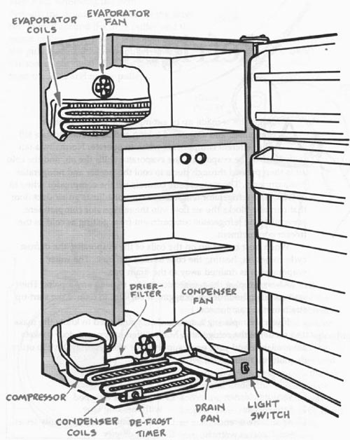
The refrigerator is made up of a compressor, a condenser, an evaporator, and associated tubing and fans. Thermostats tell the different components when to operate. Normally, a fan pulls air over the evaporator, the evaporator chills the all and the cold air is then pushed through ducts to cool the freezer and refrigerator compartments. The temperature controls tell the compressor when to operate. The refrigerator temperature control adjusts an air duct door that partially blocks the air flow into the refrigerator compartment, preventing the refrigerator compartment from getting as cold as the freezer compartment.
When frost builds up on the coils of the evaporator, the defrost cycle comes on, heating the coils to melt the frost. The water evaporates or is drained away to the drain pan.
Always unplug the refrigerator before making any repairs. Then wait about an hour before plugging it back in, to reduce the start-up strain on the compressor.
If you are replacing a door gasket, you'll need to know the make and model of the refrigerator. Many different types of door gaskets are available, and your parts supply store will probably have to order the one you need.
Tools & Materials:
- Vacuum cleaner
- Screwdriver
- Adjustable wrench
- Small socket wrench and sockets
- Putty knife wrapped with masking tape
- Volt-ohmmeter or continuity tester
- Thermometer
- Putty knife wrapped with masking tape
- Volt-ohmmeter or continuity tester
- Thermometer
--------
=============
TROUBLESHOOTING GUIDE
--------- Problem
Refrigerator doesn't run (light is out)
Refrigerator doesn't run (light is on)
Refrigerator runs but light is out
Refrigerator runs but doesn't cool
Refrigerator too cold Refrigerator noisy
--------- Probable causes
Power not reaching refrigerator
Temperature control faulty or in the OFF position
Overheating compressor
Defrost timer faulty or at defrost setting
Compressor relay faulty
Compressor overload protector faulty
Defective compressor
Burned out bulb
Defective door switch
Temperature control set too warm
Faulty temperature control
Condenser coils covered with lint
Faulty door gasket
Evaporator fan faulty
Evaporator coated with ice
Temperature control set too low
Temperature control faulty
Refrigerator not level
Drain rattling
Condenser fan faulty
-------------
Solutions:
Make sure refrigerator is plugged in.
Check for tripped circuit breaker.
Check temperature control.
Clean condenser coils.
Check condenser fan.
Check defrost timer.
Check compressor relay.
Check compressor overload protector.
Check compressor.
Replace bulb.
--
Check door switch.
Adjust temperature control to lower setting.
Check temperature control.
Clean condenser coils.
Replace door gasket.
Check evaporator fan.
Defrost refrigerator.
Check defrost timer.
Adjust temperature to higher setting.
Check temperature control.
Adjust leveling feet.
Reposition drain pan.
Check condenser fan.
===================
--------
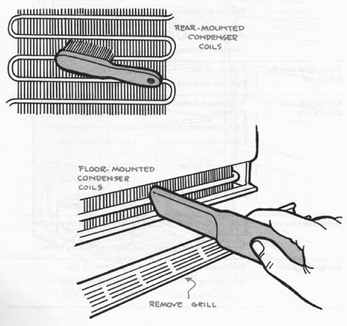
Step 4-1. Cleaning the condenser coils. Unplug the refrigerator and pull it away from the wall. Use a vacuum cleaner with a brush attachment to remove dust and accumulated lint from the coils on the back of the refrigerator. Remove the grill from the bottom front of the refrigerator, and vacuum the area behind the grill to remove accumulated dust and lint.
--------
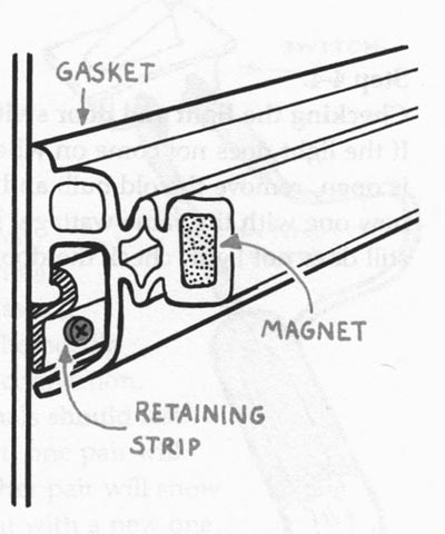
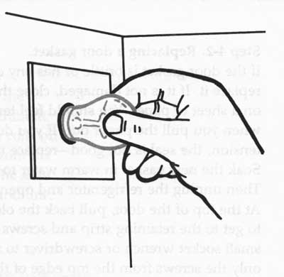
Step 4-2. Replacing a door gasket. If the door gasket is brittle or has any cracks, replace it. If it is not damaged, close the door on a sheet of paper. You should feel tension when you pull the paper out. If you don't feel tension, the seal is not good-replace the gasket. Soak the new gasket in warm water to soften it. Then unplug the refrigerator and open the door. At the top of the door, pull back the old gasket to get to the retaining strip and screws. Use a small socket wrench or screwdriver to remove only the screws from the top edge of the door and the top two screws down each side. Remove the top section of the gasket and install the new one in its place.
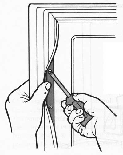
Step 4-3. Completing the job. Install the gasket retaining strip and tighten
the screws. Now repeat the procedure on the remaining three sides of the gasket,
working one section at a time. Do not remove all the screws at one time. The
door might warp out of shape.
----------
Step 4-4. Checking the light and door switch. If the light does not come on
when the door is open, remove the old bulb and install a new one with the same
wattage. If the bulb still does not light, check the door switch.
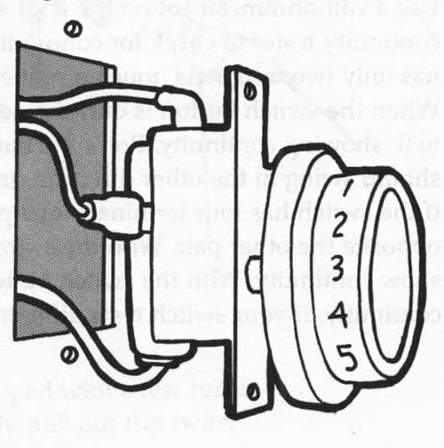
Step 4-5. Removing the door switch.
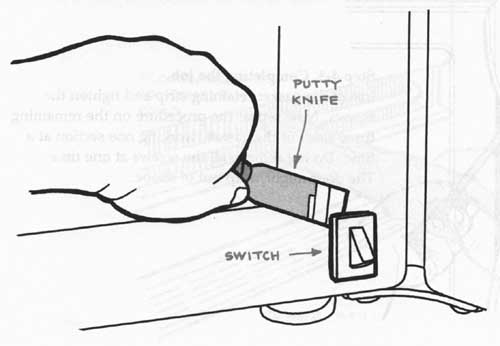
Unplug the refrigerator. Use a putty knife wrapped with a few turns of masking tape to pry out the switch. Carefully pull out the switch a few inches to get to the terminals. The switch might have one or two pairs of terminals. Label the wires and draw a wiring diagram. Now disconnect the wires from the terminals.
-----
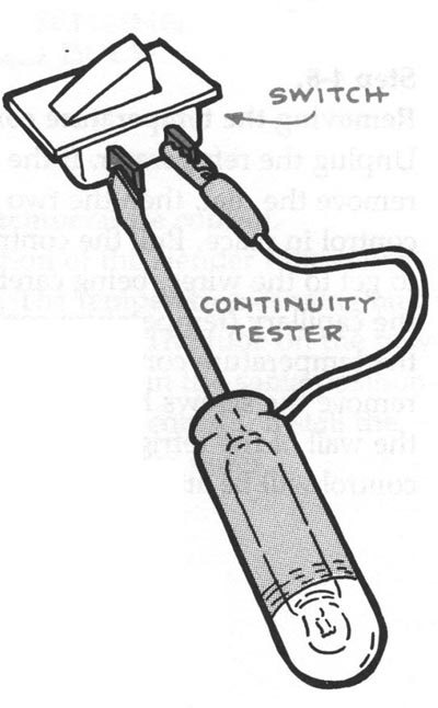
Step 4-6. Testing the door switch. Use a volt-ohmmeter set on the R x 1 scale
or a continuity tester to check for continuity. If the switch has only two
terminals, touch a probe to each terminal. When the switch button is out, the
needle should swing to 0, showing continuity. Press the button in and the needle
should swing in the other direction, indicating no connection. If the switch
has four terminals, one pair of terminals should test opposite the other pair.
With the switch button out, one pair will show continuity. With the switch
button in, the other pair will show continuity. If your switch tests differently,
replace it with a new one.
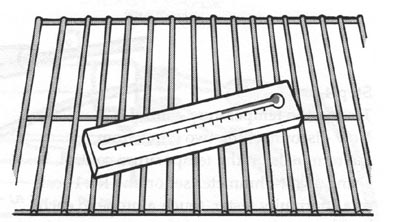
Step 4-7. Checking the temperature control. Place a thermometer in the freezing
compartment for a few minutes. The temperature should be between 0 and 8 degrees
F. Now check the temperature in the refrigerator compartment. It should be
between 38 and 40 degrees F. If the temperature control fails to produce the
desired temperature, check the temperature control.
-------
Step 4-8. Removing the temperature control. Unplug the refrigerator. If the
control has a dial, remove the dial, then the two screws holding the control
in place. Pull the control out just far enough to get to the wires, being careful
not to bend the capillary (temperature-sensing) tube. If the temperature control
is behind a console, remove the screws holding the console to the wall of the
refrigerator. The temperature control will be attached to the console.
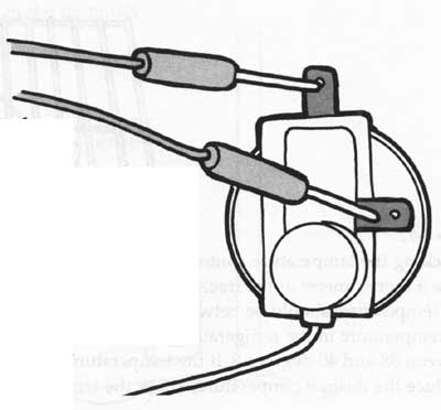
Step 4-9. Testing the temperature control Now disconnect the two wires from
the terminals on the temperature control. Using a volt-ohmmeter set on the
R x 1 scale or a continuity tester, touch a probe to each terminal of the control.
When the control knob is in the OFF position, the meter should not move. With
the control knob in the ON position or any other setting, the meter should
show continuity (the needle should move). Install a new temperature control
if the old one fails these tests.
--------------31
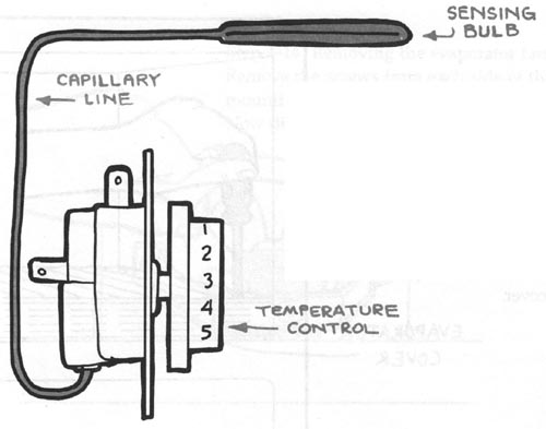
Step 4-10. Replacing the temperature control. Notice the location of the slender
tube called a capillary line. The temperature-sensing bulb is at the end of
the tube. The tube on the new control must be installed in the same position.
Carefully remove the old control, install the new one, and reconnect the wires.
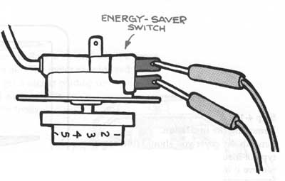
Step
4-11. Testing the energy-saver switch. If the temperature control has an energy-saver
switch, disconnect the two wires from the switch and check it for continuity
by touching a probe to each terminal. If the switch is on, the meter should
move to 0. The meter should not move when the switch is off. If the switch
fails the tests, install a new one and reconnect the wires.
-----------------
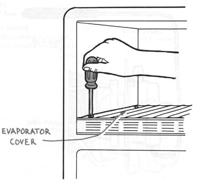
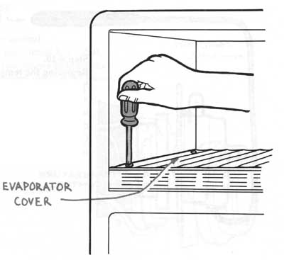
Step 4-12. Removing the evaporator cover. To check the evaporator fan, first
unplug the refrigerator and remove any ice-making equipment. Then remove the
screws holding the evaporator cover in place and remove the cover.
Step 4-13. Removing the insulation. Beneath the cover you should find some
type of insulation or heat shield. Carefully remove it from the compartment.
You should now have access to the fan.
-------------
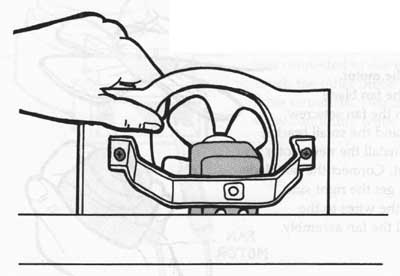
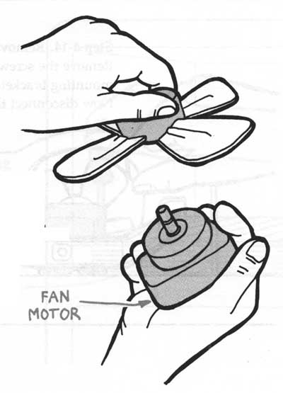
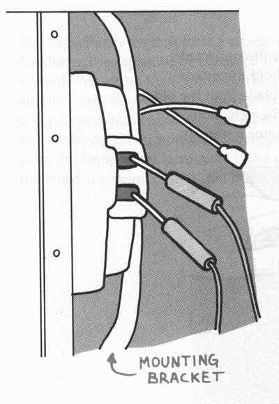
Step
4-14. Removing the evaporator fan. Remove the screws from each side of the
fan's mounting bracket and carefully lift out the fan assembly. Now disconnect
the two wires from the fan motor.
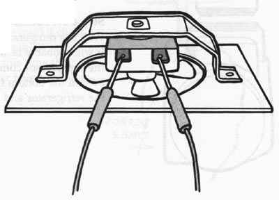
Step 4-15. Testing the fan motor. Set the volt-ohmmeter to the R x 1 scale
and touch a probe to each of the two terminals. The meter should read about
150 ohms. If you get a higher reading or no reading at all, install a new motor.
If the blade does not spin freely, install a new motor.
--------------
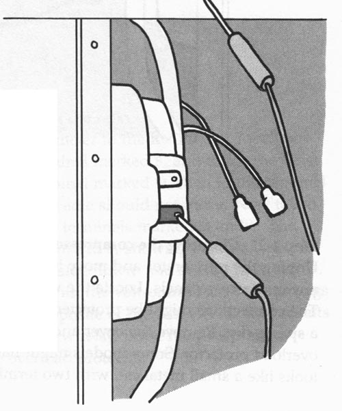
Step 4-16. Replacing the motor. Notice which side of the fan blade faces the
front. Loosen the fan setscrew. Remove the fan blade and the small bracket
in front of the motor. Install the new motor and replace the bracket. Connect
the fan blade next, making sure you get the right side facing out. Reconnect
the wires to the motor and reinstall the fan assembly.
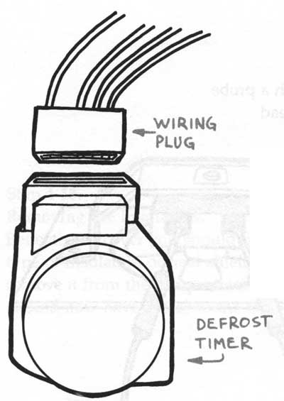
Step 4-17. Locating the defrost timer. With the refrigerator unplugged, locate
the timer. It will probably be at the back of the refrigerator in the compressor
compartment, but it also could be behind the bottom front grill. Remove the
timer from the refrigerator and disconnect the wiring plug.
---------------
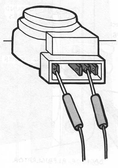
Step 4-18. Testing the defrost timer. Set the volt-ohmmeter on the R x 1 scale
and touch one probe to the terminal that was connected to the white wire in
the plug. Touch the other probe to each of the other three terminals. Two of
the terminals should show continuity while one will not.
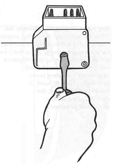
Step 4-19. Performing the second test. Use a screwdriver to turn the timer
until it clicks, and repeat the test. Again, two terminals will show continuity
and one will not, but this time they will be different terminals. If the timer
fails either test, replace it with a new one.
-------------
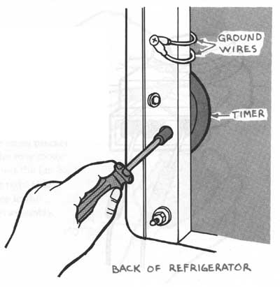
Step 4-20. Replacing the defrost timer.
Use a screwdriver to remove the timer. Disconnect any ground (green) wires, and unplug the wiring plug from the timer. Reconnect the wiring plug to the new timer and reconnect any ground wires. Mount the new defrost timer to the refrigerator.
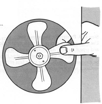
Step 4-21. Checking the condenser fan. While the refrigerator is running,
remove the front grill and feel for a draft of warm air from the condenser
fan motor. If you don't feel any air blowing, unplug the refrigerator and move
it away from the wall. Remove any rear access panels. Spin the fan blade by
hand. If you feel any resistance, the shaft is binding and the motor must be
replaced.
------
Step 4-23. Testing for a short. Now set the volt-ohmmeter to the R x 1K scale
and touch one probe to any unpainted metal part of the refrigerator. Touch
the other probe to each of the two terminals. If the needle moves at all, replace
the motor.
Step 4-22.
Testing the condenser fan motor. Unplug the two wires to the terminals on the fan motor. With the volt-ohmmeter set on the R x 10 scale, touch a probe to each of the two terminals on the fan motor. The needle should read around 75 to 150 ohms. A very high reading or no reading at all means the motor is faulty and needs to be replaced.
-------------------
Step 4-24. Installing the new motor.
With the refrigerator unplugged and the wires disconnected from the motor, disconnect the brackets that hold the motor in place and remove the motor. Remove the fan blade from the old motor and mount it on the new one. Mount the new motor in the brackets and reconnect the wires to the motor terminals.
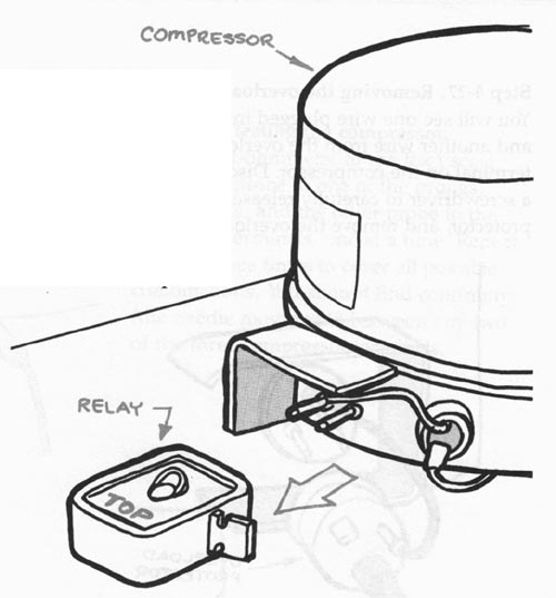
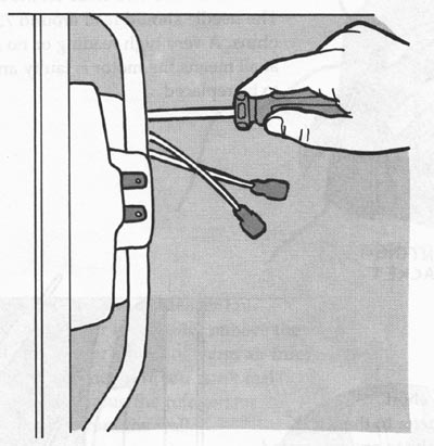
Step 4-25. Checking the compressor relay. Unplug the refrigerator and move
it away from the wall. Remove any rear access panels. Locate the wires going
into the compressor. The connections might be protected by a cover held in
place by a spring clip. Remove the cover and you will see the relay and overload
protector. Some models might have a capacitor, which looks like a small metal
can with two terminals on one end.
----------------
The capacitor is used to store a charge of electricity. Discharge the capacitor by placing a flat-blade screwdriver across the terminals. The relay is simply a switch operated by an electromagnet. It is plugged onto two of the three prongs, or terminals, on the compressor. Unplug the relay from the compressor terminals. If the relay has the word TOP printed on it, hold that side up.
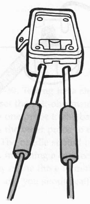
Step 4-26. Testing the relay. Set the volt-ohmmeter to the R x 1 scale. Touch
one probe to the terminal marked S, and touch the other probe to the terminal
marked M, then to the terminal marked L. The needle should not move. Now touch
the probes to the terminals marked M and L. The needle should move to 0, showing
continuity. Next, turn the relay upside down. You should hear a click. Repeat
the test with the volt-ohmmeter. The readings should be the opposite of the
first test. If your results differ, install a new relay. If the relay tests
good, check the overload protector.
-----------------
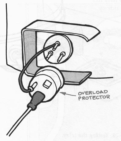
Step 4-27. Removing the overload protector.
You will see one wire plugged into a terminal on the overload protector and another wire from the overload protector connected to the remaining terminal on the compressor. Disconnect both of these wires. Now use a screwdriver to carefully release the spring clip holding the overload protector, and remove the overload protector from the compressor.
Step 4-28. Testing the overload protector. With the two wires disconnected,
set the volt-ohmmeter to the R x 1 scale. Touch a probe to each terminal on
the overload protector. The needle should move to 0, showing continuity. If
not, replace the overload protector with a new one. If the overload protector
tests good, check the compressor.
-----------------
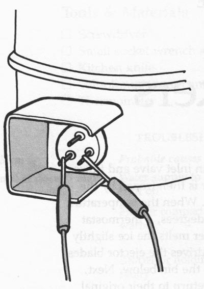
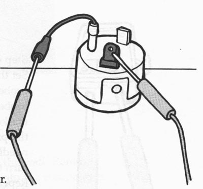
Step 4-29. Testing the compressor. Set the volt-ohmmeter to the R x 1 scale.
Touch one probe to one of the prongs, or terminals, and the other probe to
the other two terminals, one at a time. Repeat this test three times to cover
all possible combinations. You should find continuity (the needle moves to
0) between any two of the three compressor terminals.
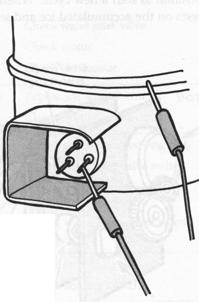
Step 4-30. Testing for a short. Now set the volt-ohmmeter to the R x 1K scale.
Touch one probe to the bare metal of the compressor. Touch the other probe
to each of the three terminals in turn. The needle should not move. If the
needle does move, indicating a connection with the metal frame, for any of
the three terminals, the compressor is faulty and you should call for service.
----------------
Home Guide/index top of page