Microwave Ovens--Operation, Maintenance, Troubleshooting + Repair
| HOME | Troubleshooting | DIY Tips |
|
← ↑ → Cooking takes place in a microwave oven because of the action of the microwaves. Microwaves are radio-frequency waves in the UHF classification. They have a higher frequency than any of the television frequencies. The Federal Communication Commission has assigned 2450 megahertz for use in microwave ovens. THEORY A thorough knowledge of the frequency which is generated by the magnetron tube is not necessary. However, the ser vice technician should be familiar with the manner in which the radio waves are conducted to the cooking cavity in the oven. Upon entering the oven cavity, the microwaves are reflected from the cabinet walls to the food. The food then absorbs the energy from these waves. This energy is then converted to heat because of the movement of the molecules in the food. The molecules move very fast in trying to align themselves with the rapidly moving radio-frequency waves. Actually, with a frequency of 2450 megahertz the molecules in the food are changing their direction four billion nine million times per second. Thus, a great deal of molecular friction is developed by this movement. It’s the generated friction that actually cooks the food. The food is cooked both inside and outside at the same time. These waves penetrate the food about 2 inches. USE OF CONTROLS The following instructions will cover the more popular types of controls that are used on microwave ovens today. Because different models and different manufacturers use different control methods, or combinations of control methods, it’s necessary that the service technician be familiar with as many of the control components as possible. Touch Controls: The operation of the touch control is listed below. Refer to Fig. 1 to learn how this control operates in the different modes. Cook 1: Cook 1 is a function that is classified as a normal cooking operation. The oven operates at 100 percent power unless it’s used in conjunction with the Power pad. To select a timed cooking operation, use the following procedure: 1. Touch the cook pad. 2. Touch the number pads corresponding to the de sired cooking time. 3. Touch the start pad. Cook 1 may also be used with a certain power level, but this involves an extra step. After step 2, if a percentage of power other than 100 percent is desired, touch the Power pad. A power level ranging from 10 to 90 % may then be selected by touching the number pad desired (e.g., “5” equals 50 percent power). Cook 2: Cook 2 is used in conjunction with Cook 1 to allow the oven to cook food at one power level in Cook I and then automatically change to a different level in Cook 2. It may also be used to extend the cooking time beyond the 99 minutes and 99 seconds of Cook 1. Start: After the desired operation has been programmed into the control, the Start pad must be touched to begin operation of the program. If the oven door is opened during operation, the microwave energy is automatically turned off. After the door is closed, the Start pad must be touched again to resume oven operation. 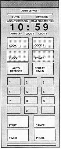 (above) Fig. 1 Typical touch control. Clock: The Clock pad is used to set the time of day or to check the time of day during the cooking operation. To set the clock, use the following procedure: 1. Touch the Clock pad. 2. Touch the number pads corresponding to the time of day 3. Touch the Start pad. Auto Defrost The automatic defrost function automatically calculates the exact amount of time and the correct power level needed to defrost the food. Select one of the three food categories (Meat, Poultry, or Fish) and enter the weight of the food being placed in the microwave. A preprogrammed standing time of 5 minutes is included in the calculated time to allow complete defrosting before the cooking process begins. To use automatic defrost, use the following procedure: 1. Touch the Auto Defrost pad. The Auto Defrost indicator light will appear and flash in the display window. The Enter Category indicator light will also flash. 2. Touch the Auto Defrost pad again to select the food category. The indicator light will move across the display window under three choices (Meat, Poultry, or Fish) as the Auto Defrost pad is touched. 3. Touch the appropriate number pads to enter the weight of the food being placed in the oven. The food weight must be entered in pounds and tenths of pounds. Refer to Table -1 for the conversion of the package weights in ounces into decimal numbers. If the weight is not entered within 3 seconds after choosing the food category, the Enter Weight indicator light will appear and flash in the display window as a signal to enter the weight of the food. If an entered weight is not within the range of the mini mum and maximum weights for each category, the control will beep, signaling that the food is too large or too small to be defrosted using the automatic defrost function of the microwave. The maximum and the minimum weight for each food category is listed in Table -2. 4. Touch the Start pad. The Auto Defrost indicator light will continue to flash in the display window. When the preprogrammed defrosting time has run out, the oven will beep and the word End will appear in the display window. Defrost (models with five power levels): For defrosting foods the control board automatically operates the oven at 30 percent power. Table -1 Conversions of ounces to tenths of a pound. Table -2 Minimum and maximum food weights allowed.
Table -3 Setting reheat times. To select an automatic defrosting operation, use the following procedure: 1. Touch the Defrost pad. 2. Set the defrost lime by touching the appropriate number pads. 3. Touch the Start pad. Power: This oven function may be used in conjunction with Cook 1 and Cook 2. The Power pad allows the user to select a percentage of operating lime for the magnetron tube. The percentage of power that may be selected ranges from 10 to 90 percent. To select a percentage of power, select the amount of operating lime in either Cook 1 or Cook 2. Touch the Power pad and any number from 1 through 9 (1 being 10 percent and 9 being 90 percent). The magnetron tube will cycle on and off for the selected percent age of lime based on a 20-second time base. Re-heat Times: The reheat times function is a time saving convenience when heating small amounts of food or beverages. The reheat times function is preprogrammed for six different reheating limes. Touch the pad from one to six times to select one of the preprogrammed settings. Cancel: If at any time during operation of the oven it’s desired to terminate an operation, touch the Cancel pad and the unit will stop its count and cancel all programs except the time of day. Probe: The automatic temperature probe feature measures the internal temperature of the food, then either turns the oven off automatically when the food is done, or holds the food at that temperature for delayed serving. To use the automatic temperature probe, use the following procedure: 1. Insert the probe into the food as close to the center as possible. 2. Plug the probe into the microwave oven jack. 3. Touch the probe pad on the oven control panel. 4. Touch the last two numbers of the desired tempera ture for the food being cooked. Note: The number 1 is automatically placed in by the control panel for the first number. 5. Touch the Start pad on the control panel. Timer: The timer can be used regardless of whether or not the oven is off or on. The timer can be set during either the cooking or the defrosting process to be used as a reminder to turn or stir foods in the middle of the cooking process. The timer does not control the cooking function. If using the timer during the cooking function, enter the function and start the oven before setting the timer. To set the timer, use the following procedure: 1. Touch the timer pad. “Time?” will appear in the upper display window. 2. Touch the number pads to set the amount of time desired. The timer can be set for any time from 1 second to 99 minutes and 99 seconds.
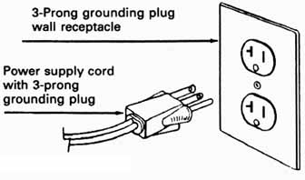
Turntable (if applicable): Models that are equipped with a turntable feature have a round glass tray in the bottom of the oven cavity that can be rotated by a motor during the oven cooking operation. This feature is used in conjunction with the stirrer to give the oven an even cooking pattern. To operate the turntable, use the following procedure: 1. Install the round glass tray into the oven cavity. 2. Set a cooking time on the control panel. 3. Press in on the Turn switch (if applicable). 4. Touch the Start pad. Note: Turntable models come with a square glass tray and a round glass tray. INSTALLATION INFORMATION Microwave ovens must be installed in the proper manner for safe and efficient operation. The following are some guidelines that may be used during the installation process. ELECTRICAL GROUNDING Microwave ovens are equipped with a three-prong grounding plug for protection against a shock hazard. These ovens must be plugged directly into a properly grounded receptacle. See Fig. 2. Don’t cut or remove the grounding prong from this plug. Use a properly polarized and grounded three-hold receptacle as required by the National Electrical Code on all new construction. The Appliance Must Be Grounded For the safety of the user, it’s required that all major appliances requiring electricity for operation be electrically grounded in accordance with the National Electric Code ANSI-1981. Check all code rules and regulations for connecting the appliance to be certain that the installation conforms with all local, municipal, and state codes as well as local utility regulations.
Fig. 2 Grounding receptacle. Power supply cord with 3-prong grounding. Where a two-prong wall receptacle is encountered, it’s the personal responsibility of the user to contact a qualified electrician and have it replaced with a properly grounded three-prong wall receptacle in accordance with the National Electrical Code. Don’t use a two-prong adaptor, since proper grounding is not assured even if the ground wire or metal tab is connected to the outlet box. Don’t use an extension cord since the ground wire could be broken without it being known. Under no circumstances should the rounded ground prong be removed from the plug. Failure to comply with the above could result in a serious shock hazard. 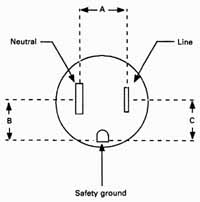 Fig. 3 Checking the polarity and ground of a wall receptacle. To remove the wrapper, use the following procedure: 1. Disconnect the electrical power from the oven. 2. Remove all 11 screws. See Fig. 4. 3. Slide the wrapper off the cabinet frame, from the rear of the oven. TESTING OUTLETS Several small plug-in testers are available to check the polarity and house grounds. It would be a wise investment for each technician to have one of these testers, especially with electronically controlled appliances that absolutely must have proper polarization and grounding. It’s imperative, even when one of the plug-in testers is not available, that the technician know how to check for proper ground and polarity. This can be accomplished very easily with an ac voltmeter. When checking a three-wire grounded receptacle, the meter should show the voltages illustrated in Fig. 3. A correctly polarized and grounded receptacle will have the small vertical slot on the right connected to the hot line, the large vertical slot on the left will be connected to the neutral, and the round opening will be the safety ground. The following tests will reveal the condition of the receptacle. See Table -4. Table -4 Testing the receptacle:
DISASSEMBLY, ADJUSTMENTS, AND REPLACEMENT OF PARTS To disassemble, adjust, or replace any of the components on a microwave oven, use the following procedures. Wrapper: The wrapper (or outer cover) is secured to the cabinet frame with two (2) screws at the bottom of each side and seven (7) screws along the back lip. Caution: Unplug the oven and discharge the capacitor before testing or removing any internal component. Important: Don’t operate the oven with the RF gasket missing. The RE gasket is located around the dome of the magnetron tube to prevent any leakage between the magnetron tube and the waveguide, with the waveguide and the oven not intact, or if the door does not fit properly. 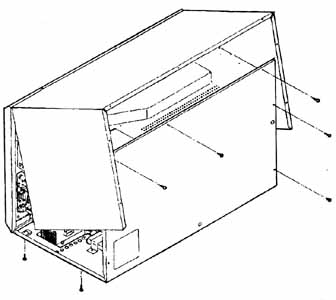 Fig. 4 Location of the wrapper screws. Stirrer Cover: The stirrer cover is held in place by eight (8) plastic rivets (four along each side). 1. Disconnect the electrical power from the unit, remove the wrapper, and discharge the capacitor. 2. Push down on each plastic rivet from the top side of the oven cavity while holding the cover in place. 3. With the rivets removed, slide the cover back to disengage it from the lip of the front frame. See Fig. 5. Stirrer Assembly: The following is a description of the stirrer assembly service procedures: To remove the stirrer from the oven, use the following procedure: 1. Open the oven door. 2. To remove the stirrer, the stirrer cover must be removed (see the Stirrer Cover section). 3. The stirrer is held into place by three (3) tabs which are part of the stirrer support. Notice that one tab slot in the stirrer blade is larger than the others. 4. With the thumb, push horizontally on the tab in the larger slot. The stirrer blade will be free from one tab. 5. Pull the stirrer from the other two tabs. See Fig. 6. To remove the stirrer support, use the following procedure: 1. Disconnect the electrical power from the unit, re move the wrapper, and discharge the capacitor. 2. The stirrer support snaps into the stirrer pulley. To release the support from the pulley, spread the tabs on the pulley and push the support shaft downward. See Fig —6. 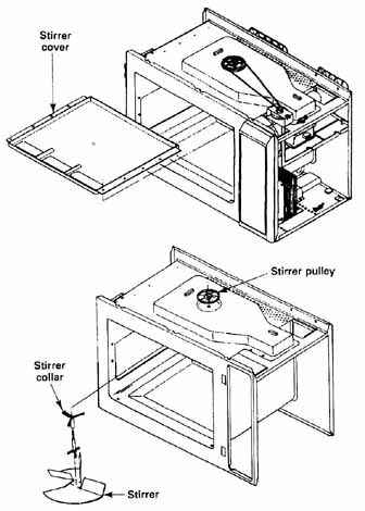 Fig. 5 (top) Stirrer cover removal. Fig. 6 (bottom) Location of the stirrer blade. To remove the stirrer collar, use the following procedure: 1. The stirrer collar snaps into the top of the oven. From the top of the oven squeeze the two-piece leg of the stirrer collar together and push downward. 2. Reach into the interior of the cavity to release the other two (2) tabs. To remove the stirrer pulley, use the following procedure: 1. Remove the belt from the stirrer pulley. Squeeze the tabs to release the pulley. See Fig. 6. Stirrer Motor: To remove the stirrer motor, use the following procedure: To remove the stirrer cover, use the following procedure: 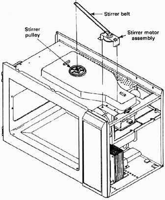 Fig. 7 Stirrer motor removal. 1. Disconnect the electrical power from the unit, re move the wrapper, and discharge the capacitor. 2. Remove the belt from the stirrer pulley. 3. Remove the screw that secures the motor mounting bracket to the chassis and lift the bracket from the chassis. 4. To disconnect the belt from the motor pulley, re move the bolts that hold the motor to the mounting bracket and disassemble the plastic guard and plastic drive pulley. See Fig. 7. Fan Assembly To remove the fan assembly, use the following procedure: 1. Disconnect the electrical power from the unit, remove the wrapper, and discharge the capacitor. 2. Disconnect the electrical leads from the fan motor. 3. Disconnect the electrical wire leads from the magnetron filament terminals. 4. Disconnect the electrical wire leads from the cavity light bulb. 5. Remove the screw from the stirrer motor mounting bracket. 6. Remove the four (4) screws from the fan air duct (2 from the top of the unit, 2 from the back of the unit). 7. Remove the fan assembly including the fan air duct. 8. Remove the fan blade by pulling it from the motor shaft. 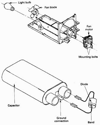 (above) Fig. 8 Fan assembly removal. (below) Fig. 9 High-voltage diode replacement. . Keep track of these parts: Fan blade; Fan motor; Diode; Capacitor; Ground connection; Band; Light bulb; Mounting bolts. 9. The fan motor can now be removed by removing the two (2) mounting nuts and bolts that secure the fan motor to the fan air duct. See Fig. 8. High-Voltage Diode: To remove the high-voltage diode, use the following procedure: 1. Disconnect the electrical power from the unit, re move the wrapper, and discharge the capacitor. 2. The diode is located at the end of the capacitor. 3. When reinstalling the diode, observe the proper diode polarity. The band on the diode should point to the ground. See Fig. 9. To replace the thermal fuse, use the following procedure: 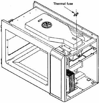 Fig. 10 Thermal fuse replacement. Thermal Fuse: 1. Disconnect the electrical power from the unit, re move the wrapper, and discharge the capacitor. See Fig. 10. 2. Disconnect the electrical leads from the thermal fuse. 3. Remove the mounting screw. Capacitor: To replace the capacitor, use the following procedure: 1. Disconnect the electrical power from the unit, remove the wrapper, and discharge the capacitor. 2. Remove the two (2) screws from the capacitor mounting bracket and lift out the capacitor. See Fig. 11. 3. If a replacement capacitor is used, replace it wire for wire to avoid making any mistakes in the wiring. 4. Reverse the above procedure to reassemble the unit. It’s important for proper grounding that the capacitor be securely attached to the cabinet base mounting bracket. Plate Transformer: To replace the power transformer, use the following procedure: 1. Disconnect the electrical power from the unit, re move the wrapper, and discharge the capacitor. 2. Disconnect all electrical leads to the transformer: primary, secondary, and the filament. 3. Remove the four (4) mounting screws from the underside of the chassis that fasten the transformer and lift the transformer out. See Fig. 12. 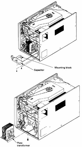
(above) Fig. 11 Capacitor replacement. (below) Fig. 12 Transformer replacement. Note the plate transformer. Note: When installing, make sure that the mounting screws are fight because these are the ground connection. Cavity Light: To replace the cavity light, use the following procedure: 1. Unplug the oven from the wall receptacle, remove the screw that secures the magnetron air duct to the back of the oven. 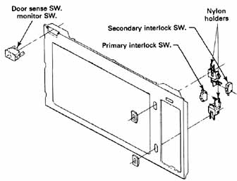
Fig. 13 Primary interlock switch replacement. 2. Lift off the air duct. 3. The bulb can now be removed. 4. Replace the bulb with a 40-watt bulb and reinstall the air duct. Note: The cavity light can be replaced by the customer. Light Socket To replace the light socket, use the following procedure: 1. Disconnect the electrical power from the unit, re move the wrapper, and discharge the capacitor. 2. Remove the light bulb. 3. Depress the prong and pull the mounting bracket out. 4. Replace the socket wire for wire to prevent any mistake in rewiring the unit. Replace the socket into the cabinet by pushing the socket into the hole provided for it. Line Fuse: Important: If the 20-amp fuse blows, refer to the troubleshooting section presented later in this section. Don’t replace the fuse until the problem is corrected. Also, if for any reason a fuse blows, internal or external, all interlock switches must be replaced. (See the interlock switches section presented later in this section.) To replace the line fuse, use the following procedure: 1. Disconnect the electrical power from the unit, re move the wrapper, and discharge the capacitor. 2. Remove the fuse from the holder. 3. A blown fuse can be diagnosed visually. The fuse will be discolored. 4. Determine what caused the fuse to blow before replacing it. 5. Replace the fuse with a 20-amp fuse. Interlock Switches: Use the following procedures to check the primary interlock switch, the safety monitor and sense switch, and the secondary interlock switches: To check the primary interlock switch, use the following procedure: 1. Disconnect the electrical power from the unit, re move the wrapper, and discharge the capacitor. 2. Remove the control panel to gain access to the interlock switch. 3. Spread the mounting bracket tabs and lift the mounting bracket from the bezel. 4. To remove the switch, spread the switch holding tabs and lift out the switch. 5. Disconnect the electrical leads to the switch. 6. Reverse the above procedure to reassemble the unit. See Fig. 13. Important: Be sure that the switch holding tabs of nylon holders are not bent, broken, or otherwise deficient in the power to hold the switches. If they are deficient, replace the holder as well as the switches. To replace the safety monitor and sense switch, use the following procedure: 1. Disconnect the electrical power from the unit, re move the wrapper, and discharge the capacitor. 2. Remove the wires from the switch. 3. Squeeze the tabs on the sides of the switch and push the switch through the front frame. See Fig. 13. To replace the secondary interlock switch, use the following procedure: 1. Disconnect the electrical power from the unit, re move the wrapper, and discharge the capacitor. 2. Remove the control panel to gain access to the switch. 3. Spread the mounting bracket tabs and lift the mounting bracket from the bezel. 4. To remove the switch, spread the switch holding tabs and lift out the switch. 5. Disconnect the electrical leads from the switch. 6. Reverse the above procedure to reassemble the unit. Important: Be sure that the switch holding tabs of nylon holders are not bent, broken, or otherwise deficient in the power to hold the switches. If they are deficient, replace the holder as well as the switches. Important: The interlock switches must meet strict federal requirements for reliable operation. It’s extremely important that any questionable switches be replaced with the exact same type switch. Defective switches must be rendered inoperative by twisting off one of the terminals. Door sense SW. monitor SW. Secondary interlock SW. Nylon holders Primary interlock SW. handle Control Panel Assembly To remove the control panel, use the following procedure: 1. Disconnect the electrical power from the unit, remove the wrapper, and discharge the capacitor. 2. Tag and disconnect the wiring from the control board. 3. Remove the two (2) screws from the control panel assembly. See Fig. 14. 4. Open the oven door and swing the bottom of the control panel out about 2 inches, then pull gently downward. 5. To separate the touch panel/circuit board from the control panel, remove the two (2) screws at the top and two (2) screws at the bottom of the control panel. Door Assembly: To remove the door assembly, use the following procedure: 1. Disconnect the electrical power from the unit, re move the wrapper, and discharge the capacitor. 2. Remove the six (6) screws that secure the hinge of the chassis and remove the door. See Fig. 15. 3. Remove the three (3) screws that secure the door handle to the door and remove the handle. 4. Lift the door cover from the assembly. 5. Remove the two (2) screws that secure the hook angle assembly to the door and remove the hook angle assembly. Door Adjustment: The door adjustment on all microwave ovens is very important to prevent any excessive leakage. The RF leakage levels should be checked after all door, interlock switches, and associated repairs are made. The following door adjustment must be performed for proper door alignment. Note: The primary and secondary interlock switches must open before the door gap exceeds 0.10 inch. To adjust the hinge side of the door, use the following procedure: 1. Disconnect the electrical power from the unit, re move the wrapper, and discharge the capacitor. 2. Loosen the six (6) screws on the hinge side until the door can be easily moved back and forth. 3. Swing the door 90°. Lift up on the end of the door until it’s level. Then hold the door in that position and lighten the screws. Important: After the repairs have been made, it’s very important to make a microwave leakage check of the door. Magnetron Assembly: To remove the magnetron assembly from the unit, use the following procedure: 1. Disconnect the electrical power from the unit, re move the wrapper, and discharge the capacitor. Control panel Hook angle assembly Mounting screws  Fig. 14 (top) Control panel removal. (below) Fig. 15 Oven door removal. Parts: Door cover Magnetron assembly removal. 2. Disconnect the electrical wires from the magnetron filament terminals. 3. Remove the two (2) screws that hold the rear of the air duct. 4. While supporting the magnetron, remove the four 5/16 inch mounting nuts. The magnetron can now be pulled down and out of the unit. See Fig. 16. 
Fig. 16 Bottom plate removal. (below Fig. 17 Probe receptacle removal. Note: The magnetron studs have metric threads, don’t loosen the nuts. Important: Don’t operate the oven with the magnetron disassembled from the waveguide. Important: Care must be taken to make sure that the RF gasket remains between the magnetron and the waveguide. Replacement magnetrons should be equipped with a new RF gasket to replace the old one. Probe Receptacle: To remove the probe receptacle, use the following procedure: 1. Disconnect the electrical power from the unit, re move the wrapper, and discharge the capacitor. 2. Remove the electrical wires from the receptacle. 3. While holding the body of the receptacle, loosen the nut on the inside of the oven cavity using a wrench. Once the nut is loose, unscrew it from the receptacle. 4. Reverse the above procedure to install a new receptacle. 5. Insert the probe and check to see that the tempera ture probe function is working. See Fig. 17. Bottom Plate (Turntable Models) To remove the bottom plate, use the following procedure: 1. Disconnect the electrical power from the unit. Remove any loose items from inside the oven cavity and set the oven on the hinge side. 2. Remove the two (2) screws from the rear of the bottom plate and slide the plate toward the rear and out of the unit. See Fig. 18. Turntable Motor (Turntable Models) To remove the turntable motor, use the following procedure: 1. Disconnect the electrical power from the unit, re move the wrapper, and discharge the capacitor. 2. Remove the bottom plate from the unit. 3. Disconnect the two (2) electrical leads from the turntable motor. 4. Remove the two (2) screws holding the turntable motor from the inside of the oven cavity. 5. Lift the square drive from the motor shaft and pull the motor out of the unit. See Fig. 18. TROUBLESHOOTING Checking Power Wattage There are two power wattages indicated on the model serial plate of each microwave oven. For example, the following information may be printed below the model/serial number:
From the above example, “1500 W” is the amount of power wattage needed to operate the oven during a full power cooking cycle (input power wattage). “OUTPUT 700 W,” on the other hand, is the amount of power wattage produced by the magnetron assembly during a full-power cooking cycle (output power wattage). When testing a microwave oven for power wattage, the output power wattage must be checked. To perform this test and obtain more accurate results, two 1-liter (microwave safe) containers and a glass Centigrade scale thermometer should be used. To check the output power wattage, use the following procedure: 1. Fill the two 1-liter containers with tap water. 2. Stir the water in each container with the thermometer and record the temperature of each container. 3. Find the average temperature of the two containers by adding the two temperatures together and dividing the total by 2. 4. Place both containers in the center of the micro wave oven cavity. 5. Set the oven power level to the highest setting and operate the oven for exactly 2 minutes. 
(left) Fig. 18 Bottom plate removal. Parts: Turntable motor Screws. (right) Fig. 19 Discharging the capacitor. Note: When testing an oven with a mechanical timer, use an accurate watch for better timing accuracy. 6. When 2 minutes have elapsed, stir each container again with the thermometers and record the temperatures. 7. Find the average temperature of the two containers by adding the two temperatures together and dividing the total by 2. 8. Subtract the average temperature determined in step 3 from the average temperature determined in step 7 to determine the temperature rise. 9. Multiply the temperature rise by a factor of 70 to determine the approximate output power wattage. 10. Compare the result in step 9 with the output power wattage printed on the model/serial plate of the unit tested. If the result is within 10 percent of the stated output, the oven has sufficient cooking capabilities. Discharging the Capacitor To discharge the capacitor, use an insulated handle screwdriver and a 29-inch jumper wire with alligator clips. 1. Connect one end of the wire to the screwdriver blade and the other end to the case of the capacitor, or chassis of the oven. 2. Place the screwdriver blade across the terminals of the capacitor. See Fig. 19. * The 10 percent allowance in output power wattage is due to the voltage operating range of the microwave oven (110 to 120 volts). This is noted in the owner’s manual by refer ring to a “range of cooking time” (i.e., “2 to 3 minutes”) when heating food. NEXT: ← ↑ → Home top of page |
