Electric water heaters--Troubleshooting and Repairing
| HOME | Troubleshooting | DIY Tips |
|
TOPICS
Electric water heaters are heat-producing appliances. They normally have two heating elements (Figr.1), with each element controlled by a thermostat. The thermostats are mounted on the outer wall of the water heater tank just above the elements, from where they sense the temperature of the water through the outer wall of the water heater tank. A temperature and pressure relief valve, which is mounted on the outside of the tank, is a device applied to a water heater which will open to pass water or steam, if excessive pressure or temperature occurs in the water heater tank. Electric water heaters are available in many different sizes of height and width. They are similarly available in different capacities. PRINCIPLES OF OPERATION The water heater tank is full of water; the electricity is on; the upper thermostat (Figr.1) senses that the water is cold; and this condition energizes the upper element. At the same time, the lower element is not activated. The upper heating element will heat approximately one quarter of the tank’s capacity. When the temperature of the water reaches the thermostat setting, the upper thermostat will shut off. Then, the lower thermostat becomes energized and heats the remainder of the water in the tank. When the temperature of the water reaches the thermostat setting, the lower thermostat will deactivate the lower heating element. The tank is now filled with hot water. As the consumer uses the hot water, hot water is drawn from the top of the tank, and is re placed with cold water through a dip tube (Figr.1) located near the bottom of the tank. When the lower thermostat senses the cold water, the thermostat activates the lower heating element, heating the water. Figr. -2 identifies one of the many types of thermostats. Also, in the same figure, there is a schematic drawing showing the thermostat switch contacts. SAFETY FIRST Any person who cannot use basic tools, or follow written instructions, should not attempt to maintain or repair any electric water heaters. Any improper installation, preventive maintenance, or repairs could create a risk of personal injury or property damage. 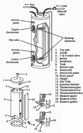
__1 Exploded view of the electric water heater. Hot line; Cold line; Heating elements; Upper thermostat 1. Top pan 2. Anode 3. T&P relief valve 4. Jacket 5. Insulation 6. Tank 7. Bottom pan 8. Draincock 9. Draincock panel 10. Front panel 11. Nipple 12. Dip Tube 13. Junction bracket 14. Thermostat-upper 15. Thermostat-lower 16. Thermostat-bracket 17. Element-upper 18. Element-lower 19. Element gasket If you don’t fully understand the preventive maintenance or repair procedures in this section, or if you doubt your ability to complete the task on your electric water heater, then please call your service manager. These precautions should also be followed: 1. Before checking the water heater, turn off the electricity. 2. Never restore the electricity to the water heater if the tank is empty; do so only after it’s full of water. 3. Never remove the heating elements with the tank full of water. 4. If a water heater needs to be replaced, it’s strongly recommended that all electrical, plumbing, and placement of the tank should be done by qualified personnel. Observe all local codes and ordinances for electrical, plumbing, and installation procedures. Before continuing, take a moment to refresh your memory concerning the safety procedures in Section 2. 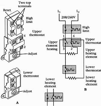 __2 A. Typical upper and lower water heater thermostats. B. Wiring schematic for upper and lower thermostat. ELECTRIC WATER HEATERS IN GENERAL Much of the troubleshooting information in this section covers electric water heaters in general, rather than specific models, in order to present a broad overview of ser vice techniques. The pictures and illustrations that are used in this section are for demonstration purposes; for clarifying the description of how to service these heaters. In no way do they reflect on a particular brand’s reliability. ELECTRIC WATER HEATER MAINTENANCE Every so often, inspect the water heater tank for possible water leaks. Check the following:
1. Check all pipe connections to the tank. If corroded, they must be repaired before there is serious water damage to the property. 2. Check the temperature/pressure relief valve. Is it leaking? 3. Turn off the electricity, remove the access panels, inspect the wiring, elements, and insulation for signs of water leakage. If water is leaking, the leak must be repaired, or the unit must be replaced immediately. Once a year the water heater tank should be drained and flushed out. By doing this procedure, it will increase the life expectancy of the tank by removing the unwanted sediment. Before you begin draining the tank, turn off the electricity to the water heater. To drain the water heater tank, turn off the water supply to the tank. Connect a garden hose to the draincock, and open the valve. To increase the water flow draining out of the tank, open the hot water faucet, this will increase the flow of water draining out of the tank. When you are ready to refill the tank, close the draincock, turn on the water supply to the water heater, and begin to refill the tank. Leave the closest hot water faucet open during refilling; the air that is trapped in the tank will escape through the hot water faucet. When all of the air is out of the tank and water lines, close the hot water faucet. Go to all of the other hot water faucets and open them to remove the air in the lines. Close all water faucets. Now you are ready to turn on the electricity to the water heater. STEP-BY-STEP TROUBLESHOOTING BY SYMPTOM DIAGNOSIS In the course of servicing an appliance, don’t tend to overlook the simple things which may be causing the problem. Step-by-step troubleshooting, by symptom diagnosis, is based upon diagnosing malfunctions with their possible causes arranged into categories relating to the operation of the water heater. This section is intended only to serve as a checklist to aid you in diagnosing a problem. Look at the symptom that best describes the problem that you are experiencing with the water heater, then proceed to correct the problem. No hot water 1. Do you have the correct voltage at the water heater? 2. Check for loose wiring. 3. Check to be sure the reset button did not trip. 4. With the electricity off, check the thermostats for continuity. 5. With the electricity off, check the heating elements for continuity. Also check for a grounded heating element. Not enough hot water 1. Is the water heater undersized for the usage? 2. Check the lower heating element for continuity. Also check for a grounded heating element. 3. Check for leaking faucets and pipes. 4. Check to see if anyone is wasting water. 5. Drain the tank; remove lower element; see if any sediment is in the bottom of tank, or around the heating element. 6. Is there any lime formation on the elements? 7. Are the thermostats operating properly? Run a cycle test. 8. Check the thermostat settings. Verify if they are set too low. Water too hot 1. Check to see if the thermostat is snug against the tank. 2. Is the thermostat set too high? 3. Are the thermostats operating properly? Run the cycle test. 4. Check for a grounded element. Water heater element failure 1. Check for loose or burned wiring connections. 2. Check for the correct voltage to the elements. 3. Is the element shorted or grounded? Test the elements for continuity. Discolored or rusty water 1. Drain the tank; remove the lower element; see if there is any sediment in the bottom of the tank. 2. Is the water supply to the water heater rusty in color? 3. Check the water for softness. 4. Check to see if there are excessive mineral deposits. 5. Inspect the anode rod to note its condition. If it did dissipate, replace the anode. Repair procedures Each repair procedure is a complete inspection and repair process for a single water heater component; containing the information you need to test a component that may be faulty; and to replace it, if necessary. Upper thermostat The typical complaints associated with the upper thermostat are: 1. No hot water. 2. Burned wires. 3. Water heater runs continuously. 4. The fuse blows, or the circuit breaker trips. 1. Verify the complaint To verify the complaint, turn on the hot water. Does the water get hot? 2. Check for external factors-- You must check for external factors not associated with the water heater. Is the water heater installed properly? Does the water heater have the correct voltage? 3. Disconnect the electricity--Before working on the water heater, disconnect the electricity. This can be done by pulling the plug Out of the electrical outlet. Or disconnect the electricity at the fuse panel or at the circuit breaker panel. Many installations have a disconnect switch/breaker box near the heater. Turn off the electricity. 4. Remove the access panel--To gain access to the upper thermostat, the access panel must be removed (Figr.1). The access panel is held on with 2 screws on most models. Peel back the insulation; then, remove the thermostat protective cover. 5. Test the thermostat--To test the upper thermostat, use your voltmeter. Set the range on the 300-volt scale. Touch the probes to terminals 1 and 3 above the reset button (Figr.3). Turn on the electricity. If the meter reads no voltage, have the customer call an electrician to find out where the power failure is. If the meter reads the proper rated voltage, as stated on the name plate, the electricity is okay. Next, touch the probes to terminals 2 and 4 below the reset button (Figr.4). If the meter reads the proper rated voltage, the electricity is okay. If the meter reading is “0” volts, press the reset button on the thermostat. If there is still no voltage reading on the meter scale, either the water temperature in the tank is too hot, or the thermostat is inoperative. At this stage, again turn off the electricity to the tank. Remove the wires from the upper heating element (Figr.5). Be absolutely sure that the electricity is OFF before any further tests are made using your ohmmeter. Use your ohmmeter to test terminals 1 and 2 on the upper thermostat (Figr.5). If the thermostat is calling for heat, the ohmmeter needle will swing to the right showing continuity. Now, touch the probes to terminals 1 and 4 on the thermostat (Figr.6). If the water in the tank is cold, you won’t get a reading on the ohmmeter scale. If the water in the tank is hot, as called for by the thermostat, the needle will swing to the right, thus showing continuity. 6. Cycle the upper thermostat--Reconnect the wires to the heating element. Turn on the electricity to the tank. Take your ammeter and clamp the jaws around the wire that goes from terminal number 4 to the upper element 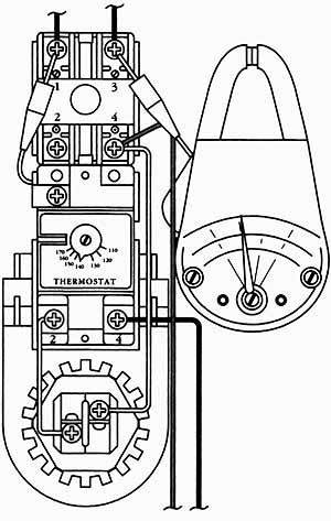 __3. Place the voltmeter probes on terminals I and 3 to check the voltage. 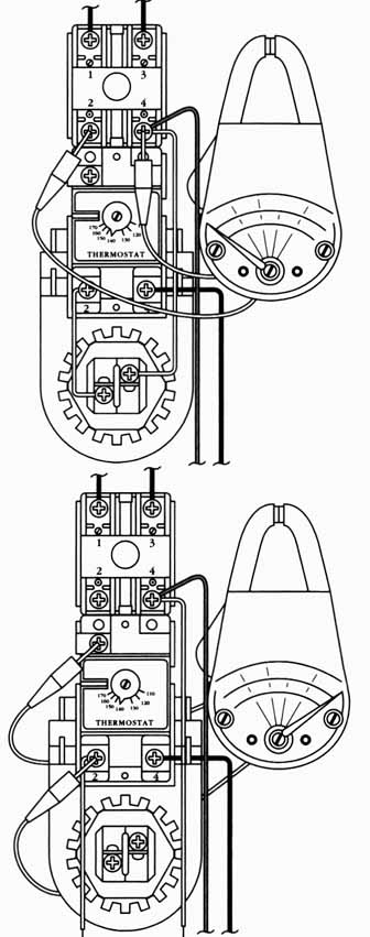 __4. Place the voltmeter probes on terminals 2 and 4 to check the voltage. __5. Remove the wires from the element. Place the ohmmeter probes on terminals 1 and 2. When the thermostat is calling for the element to turn on, the ohmmeter scale will read continuity. (Figr.7). With cold water in the tank, and the thermostat calling for heat, you should get a reading on the meter in amps. The reading you get will depend on the rating (in watts) of the heating element, divided by the voltage supplied (see the formula in Figr.8). After the temperature is reached, the needle on the ammeter scale will read “0.”  __6. Place the ohmmeter probes on terminals 1 and 4. If the water in the tank is cold, the ohmmeter scale will read no continuity __7. The ammeter jaws encircled on the number 4 terminal wire go to the element. Conversion chart for determining amperes, ohms, volts, or watts Amperes = A, Ohms = C Volts = V, Watts = W 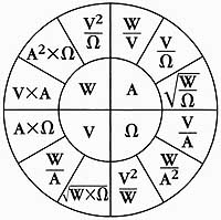 __8. Ohm’s Law equation wheel: the conversion chart for deter mining amperes, ohms, volts, or watts. Next, place the ammeter jaws on the number 4 terminal wire, that goes from the upper thermostat (just below the temperature gauge setting) to the lower element (Figr.9). The ammeter should show a reading, indicating that the lower element is working. 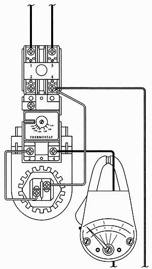 __9. Place the ammeter jaws around terminal 4. The ammeter reading is 0. 7. Replace the upper thermostat--Turn off the electricity to the water heater. To replace the upper thermostat, remove all of the wires from the thermostat. Be sure that you mark the wires so that you can replace them exactly the way you took them off. Next, pry back the thermostat bracket with your fingers far enough to slide the thermostat up and out; remove the thermostat. To install the new thermostat, just reverse the disassembly procedure, and reassemble. Be sure that the thermostat is snugly mounted against the tank so that it can sense the temperature better. 8. Test the new upper thermostat--After you have completed the new installation, turn on the electricity to the water heater. Repeat this testing process as described, and verify that the new unit is working correctly. Lower thermostat: Testing the lower thermostat is similar to testing the upper thermostat; with the following exception. With the wires removed from the element, place the ohmmeter’s probes on each terminal. Take a screwdriver and place it on the set screw of the thermostat, and turn it clockwise. The needle on your ohmmeter will swing to the right, indicating that there is continuity. If the needle does not move, the thermostat needs to be replaced. Replace this thermostat as per the upper thermostat replacement previously described. Then, test the thermostat by placing the jaws of the am meter around the wire that connects to the lower thermostat. Check to be sure that the thermostat cycles on and off. Heating element: The typical complaints associated with the heating element are: 1. No hot water. 2. Burned wires. 3. The fuse blows, or the circuit breaker trips. 1. Verify the complaint--To verify the complaint, turn on the hot water. Does the water get hot? 2. Check for external factors-- You must check for external factors not associated with the water heater. Is the water heater installed properly? Does the water heater have the correct voltage? 3. Disconnect the electricity--Before working on the water heater, disconnect the electricity. This can be done by pulling the plug out of the electrical outlet. Or disconnect the electricity at the fuse panel, the circuit breaker panel, or the disconnect switch. Turn off the electricity. 4. Remove the access panel In order to gain access to the heating element, the access panel must be removed (Figr.1). The access panel is held on with two screws on most models. Peel back the insulation; then, remove the wires from the heating element. 5. Test the heating element--Use the ohmmeter to test the heating element. Set the range to R x 1. Touch the probes to the element screws (Figr.10). If the element is good, the ohmmeter scale will show continuity. If the element is bad, the ohmmeter needle won’t move, showing an open element. Now, set the ohmmeter on R x 100. Take one probe and place it on either terminal of the element. Take the other probe and touch the element head (Figr.11). If you get any reading, the element is grounded, and it should be replaced. Repeat this procedure for the other terminal on the element. Both terminals must be measured for grounding. 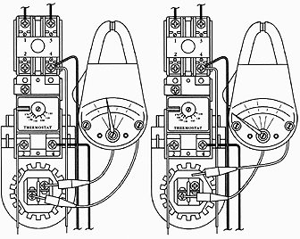 __10. Testing heater element. Place the ohmmeter probes on the screw terminals of the element. __11. Testing the heater element for the ground. 6. Remove the element--Turn off the electricity to the water heater. Next, turn off the water supply. Connect a garden hose to the draincock, and open the draincock. At the same time, open a nearby faucet to allow the water to drain faster. After the tank is empty, disconnect the wires from the element and remove it. 7. Install the new element--To install the new element, just reverse the disassembly procedure, and reassemble. When installing the new element, always replace the gasket. Before you insert the new element into the tank, clean the flange of debris. 8. Test the new element--When you are done installing the replacement element, close the draincock, and open the water supply. Close the nearby faucet after all of the air in the tank has dissipated. Next, check for water leaks. Turn on the electricity to the water heater. Use the ammeter to check the element. The ammeter should show a reading. DIAGNOSTIC CHARTS The following diagnostic flow charts, wiring diagrams, and tables will help you to pin point the likely causes of the problem (Figrs. 12 through 19; Tables 1 and 2). To electric power supply. 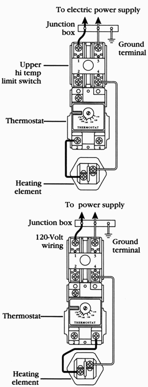 __12. Pictorial wiring diagram for a standard 2-wire 208-/240-voft circuit, single element. __13. Pictorial wiring diagram for a standard 2-wire 208-/240-voft circuit, single element. To power supply; Junction box; Upper hi temp limit switch; 120-Volt wiring; Thermostat 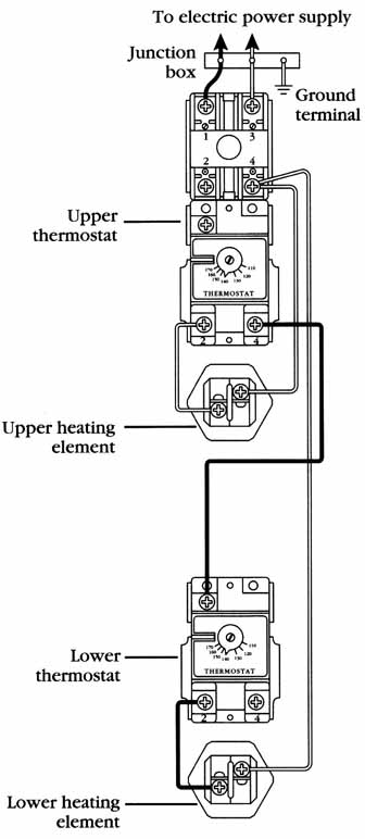
__14. Pictorial wiring diagram for a standard 2-wire interlocking 208-/240-/277-volt circuit, double element. 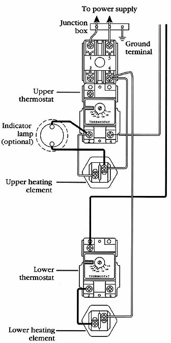
__15. Pictorial wiring diagram for a 4-wire off-peak double-element non-simultaneous operation. Upper thermostat; Upper heating element thermostat Circuit breaker out or blown fuse. Check for voltage at water heater—No--Check fuse/ circuit breaker Yes--Check for a short in the circuit Yes Locate the short; circuit and correct. No Check the for wrong wiring connections-- Yes Correct the wiring connections according to wiring diagram. 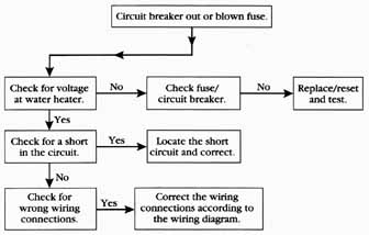
__16 Water heater flow chart circuit breaker out or fuse blown. Circuit breaker out or blown fuse. Check for voltage at water heater. NO. Check fuse/circuit breaker. YES Check for a short in the circuit. YES. Locate the short circuit and correct. NO. Check for wrong wiring connections. YES. Correct the wiring connections according to the wiring diagram. 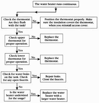 __17. Water heater flow chart: water heater runs continuously. The water heater runs continuous. Check the thermostat. Are they flush with the tank? NO. Position the thermostat properly. Make sure the insulation covers the thermostat, when you reinstall access cover. YES. Check upper thermostat for proper operation. YES. Check lower thermostat for proper operation. YES. Check for water leaks on the tank. Check for any open faucets. NO. Is the water heater undersized. YES. Replace the water heater with a larger water heater. 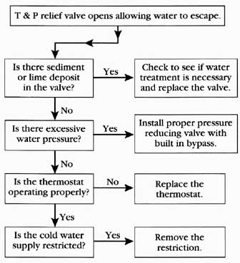 __18. Water heater flow chart: relief valve opens. T & P relief valve opens allowing water to escape. Is there sediment or lime deposit in the valve? No. Is there excessive water pressure? No. Is the thermostat operating properly? Is the cold water supply restricted? YES: Check to see if water treatment is necessary and replace the valve. Install proper pressure reducing valve with built in bypass. Replace the thermostat. Remove the restriction. 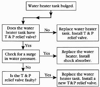 __19. Water heater flow chart: water heater tank bulged. Does the water heater tank have T & P relief valve? Yes. Check for a surge in water pressure. No. Is the T & P relief valve faulty? 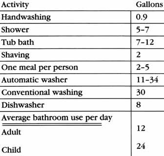 Table 1. Typical Hotwater Usage Chart Activity | Gallons
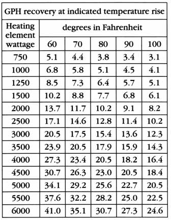 Table 2. Electric Water Heater Recovery (Calculated at 100% recovery efficiency). GPH recovery at indicated temperature rise. Heating element wattage. degrees in Fahrenheit. Prev: Automatic dishwashers Next: Automatic washers Home top of page All related articles |