AMAZON multi-meters discounts AMAZON oscilloscope discounts
LEARNING GOALS:
• identify the grounded and ungrounded conductors in cable or conduit (color coding).
• identify the various types of toggle switches for lighting circuit control.
• select a switch with the proper rating for the specific installation conditions.
• describe the operation that each type of toggle switch performs in typical lighting circuit installations.
• determine when a neutral conductor must be added for switch boxes.
• demonstrate the correct wiring connections for each type of switch per Code requirements.
• understand the various ways to bond wiring devices to the outlet box.
• understand how to design circuits to avoid heating by induction.
WARNING! Improper wiring can result in fires, personal injuries, and electrocutions! All wiring must be done in conformance to the NEC. Anything less is unacceptable!
CONDUCTOR IDENTIFICATION (ARTICLES 200 AND 210)
Before making any electrical connections, an electrician must understand conductor color coding.
Ungrounded Conductor. An ungrounded conductor must have an outer finish that is a color other than green, white, gray, or three continuous white stripes.
This conductor is commonly called the "hot" conductor. You will get a shock if this "hot" conductor and a grounded conductor or grounded surface such as a metal water pipe are touched at the same time.
Popular colors for cable wiring systems are black, red, and sometimes blue. Many other colors are available for conduit systems including blue, yellow, brown, orange, and purple.
Grounded Conductor. For alternating-current circuits, the NEC requires that the grounded (identified) conductor have an outer finish that is either continuous white or gray, or have an outer finish (not green) that has three continuous white stripes along the conductor's entire length. From a NEC definition standpoint, a neutral conductor connects to the neutral point. In multiwire circuits, the grounded conductor is also a neutral conductor.
Three Continuous White Stripes. In house wiring, you will probably never run across a conductor that has three continuous white stripes on other than green insulation. This method of identifying conductors is done by the cable manufacturer and would be found on larger size conductors and some that may be used by the electric utility. Some underground service conductors such as those used for a mobile home feeder may have two black conductors, one black conductor that has three white stripes, and one green conductor.
Grounded Neutral Conductor:
For residential wiring, the grounded conductor with white insulation is commonly referred to as the neutral. However, this conductor is not always a neutral conductor, as you will learn.
For branch circuits and feeders, the grounded neutral conductor must be insulated, 310.106(D). For residential services, the grounded neutral conductor is permitted to be insulated or bare, 230.41.
For residential wiring, the 120/240-volt electrical system is grounded by the electric utility at their transformer, and again by the electrician at the main service. This is in accordance with 250.20(B)(1) requiring that the system be grounded if the maximum voltage to ground on the ungrounded conductors does not exceed 150 volts. NEC 250.26(2) requires that the neutral conductor be grounded for single-phase, 3-wire systems.
Electricians often use the term "neutral" whenever they refer to a white grounded circuit conductor. The correct definition is found in the NEC.
Neutral Conductor. The conductor connected to the neutral point of a system that is intended to carry current under normal conditions.* See Fgr. 1.
Neutral Point. The common point on a wye connection in a polyphase system or midpoint on a single-phase, 3-wire system, or midpoint of a single phase portion of a 3-phase delta system, or a midpoint of a 3-wire, direct current system.* See Fgr. 1.
By these definitions, the white grounded conductor in a 2-wire circuit is a neutral conductor. In a multiwire 3-wire branch circuit, the white grounded conductor is a neutral conductor. See Fgr. 1.
For those of you who will broaden your training into commercial and industrial wiring, you will find that there are electrical systems such as a 3-phase delta connected corner grounded system where the grounded conductor is a phase conductor and is not a neutral conductor. This is covered in detail in the Electrical Wiring-Commercial text.
A neutral conductor in residential wiring is always a grounded conductor-but a grounded conductor is not always a neutral conductor.
Although it may seem obvious to trained electricians, NEC 200.2(B) prohibits using a metal enclosure, a metal raceway, or metal cable armor to be part of a grounded conductor's path. Always connect the neutral conductor to the terminal bar for the neutral conductors rather than to an equipment grounding terminal bar.
===
Neutral conductor, Neutral point, Equipment grounding conductor carries current only under abnormal conditions.
Carries current under normal conditions 120/240-V, 1-phase, 3-wire 120 240120 Line-to-neutral connected loads Service Line-to-line connected loads
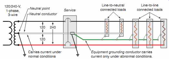
FGR. 1 Definition of a neutral conductor and neutral point.
===
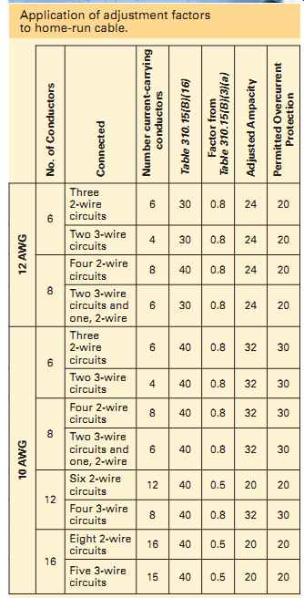
TABLE 1 Application of adjustment factors to home-run cable.
No. of Conductors Connected Number current-carrying conductors
Table 310.15(B)(16) Factor from Table 310.15(B)(3)(a) Adjusted Ampacity Permitted Overcurrent Protection
===
Multiwire Branch-Circuit
The Code defines a multiwire branch circuit as A branch circuit consisting of two or more ungrounded conductors having a voltage between them, and a grounded conductor having equal volt age between it and each ungrounded conductor of the circuit and that is connected to the neutral or grounded conductor of the system.* For additional information relative to the hazards involved with multiwire circuits, refer to Fgrs. 5, 6, 7, 8, and 9 in Section 17.
Color Coding (Cable Wiring)
The conductors in nonmetallic-sheathed cable (Romex) are color coded with insulation as follows:
2-wire: one black ("hot" phase conductor) one white (grounded "identified" conductor) one bare, covered, or insulated (equipment grounding conductor) 3-wire: one black ("hot" phase conductor) one white (grounded "identified" conductor) one red ("hot" phase conductor) one bare, covered, or insulated (equipment grounding conductor) 4-wire: one black ("hot" phase conductor) one white (grounded "identified" conductor) one red ("hot" phase conductor) one blue ("hot" phase conductor) one bare, covered, or insulated (equipment grounding conductor) Four-wire nonmetallic-sheathed cable is also available with two ungrounded ("hot") and two neutral conductors. This cable is designed for wiring two 120-volt branch circuits without using a common neutral. This avoids the requirement of installing a tie handle on the circuit breakers or installing a 2-pole circuit breaker.
This cable has the following insulated conductors:
• one black ("hot" phase conductor)
• one white with a black stripe (grounded "identified" conductor)
• one red ("hot" phase conductor)
• one white with a red stripe ("hot" phase conductor)
• one bare, covered, or insulated (equipment grounding conductor)
Manufacturers of Type MC cable also make a "home run cable." This cable is available with 6 or 8 12 AWG conductors and with 6, 8, 12, and 16 10 AWG conductors. The insulation is THHN/THWN, so derating [required by NEC 310.15(B)(3)] is started in the 90°C column of NEC Table 310.15(B) (16). Table 1 illustrates application of derating for the number of current-carrying conductors in the home run cable. Notice that the number of current carrying conductors can change depending on how connections are made.
In every case, the allowable ampacity of the conductors after application of the adjustment factors permits a 20-ampere overcurrent device to be used.
In some installations, home run cable can be used rather than installing a subpanel some distance away from the service equipment.
Color Coding (Raceway Wiring)
When the wiring method is a raceway such as EMT, the choice of colors for the ungrounded "hot" conductors is virtually unlimited, with the following restrictions:
Green or green with yellow stripe(s): Reserved for use as an equipment grounding conductor only. Not permitted to be used as a grounded or ungrounded conductor. See 250.119 and 310.12(B).
White or gray: Reserved for use only as a grounded circuit conductor (neutral). See Table 2 for more information about identifying conductors.
What about Conductors with Gray Insulation?
The NEC recognizes a conductor with gray insulation to be used as a grounded conductor. See 200.6(A) and (B).
The NEC prohibits a conductor with gray insulation to be used as an ungrounded "hot" conductor.
See 200.6(A) and (B).
For years, conductors with gray insulation were used in commercial and industrial installations as both grounded conductors and ungrounded conductors. Past editions of the NEC used the term natural gray, but no one really knew what it was. Was it "dirty white"? Was it "light gray"? Was it "dark gray"? Confusion was the end result.
To bring an end to the confusion, all references to the term natural gray have been deleted in the NEC.
You might be saying to yourself, "No cable that I use for house wiring has a gray conductor in it." Right! But in commercial and industrial work, there are situations where two systems are installed in the same raceway, such as a 120/208-volt and a 277/480-volt circuit. This is an example of where you might want to use a white insulated conductor for the 120/208-volt system neutral conductor, and a gray insulated conductor for the 277/480-volt sys tem neutral conductor.
===

TABLE 2
Changing colors of conductor insulation in a raceway or cable.
To Change This . . . to This, Do This
red, black, blue, etc. … an equipment grounding conductor
Conductors 6 AWG or smaller: No re-identification permitted for conductors 6 AWG and smaller. An equipment grounding conductor must be bare, covered, or insulated. If covered or insulated, the outer finish must be green or green with yellow stripes. The outer finish color must run the entire length of the conductor.
Conductors larger than 6 AWG: Insulation on large conductors is usually black but may have other colors. Therefore, at time of installation, at both ends and at every place where the conductor is accessible except in a conduit body where there are no splices, do any one of the following:
• strip off the insulation for the entire exposed length, or…
• at the termination, encircle the insulation with green color, or…
• at the termination, encircle the insulation with a few wraps of green tape, green adhesive labels, or green heat shrink tubing See 210.5(B), 250.119, and 310.110(B).
---
red, black, blue, etc. ... a grounded conductor ...
Conductors 6 AWG or smaller: For the conductor's entire length, the insulation must be white, gray, or have three continuous white stripes on other than green insulation. Re-identification in the field is not permitted when the wiring method is a raceway.
Conductors larger than 6 AWG: For the conductor's entire length, the insulation can be white, gray, or have three continuous white stripes on other than green insulation.
If not white, gray, etc., re-identification at terminations to be white or gray paint, tape, or heat shrink tubing. This marking must encircle the conductor or insulation. Do this marking at time of installation.
Identification must encircle the conductor.
See 200.2, 200.6(A) and (B); 200.7(A), (B), and (C); 210.5(A); and 310.110(A).
… white, gray ... an ungrounded (hot) conductor ...
Change permitted for cables but not for raceways: Insulated conductors that are white, gray, or have three continuous white stripes are to be used only as grounded conductors in raceways.
Conductors that are part of a cable assembly having white or gray insulation are permitted to be re-identified for use as an ungrounded conductor by marking tape, painting or other effective means.
Re-identification required at each location the conductor is visible, accessible and at terminations.
For switch loops, the re-identified conductor is to be the supply to the switch but not the return.
See 200.7(A), (B), and (C); and 310.110(C).
===
Black plastic tape TYPE NM-B A B
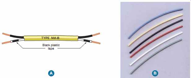
FGR. 2 Shows a white conductor re-identified with black plastic electrical
tape.
(B) Shows an assortment of easy-to-use, 6-in.-long heat shrink tubing that is slid over the conductor to be re-identified, then shrunk tightly over the conductor by applying heat as specified in the instructions. (-)
===
Changing Colors When Conductors Are in a Cable
The basic rule in 200.6 is that grounded conductors must be white, gray, or have three continuous white stripes on other than green insulation.
For cable wiring such as nonmetallic-sheathed cable or armored cable, 200.7(C)(1) permits the white or gray conductor to be used for single-pole, 3-way, or 4-way switch loops. These sections require that when used for a switch "loop," the conductor that is white, gray, or marked with three continuous white stripes is to be used for the sup ply to the switch, and not as the return conductor from the switch to the switched outlet. Also, the conductor must be permanently re-identified to indicate its use by painting or other effective means, at its terminations and at each location where the conductor is visible and accessible. See Fgr. 2.
A new requirement for providing a neutral conductor at all switch boxes trumps the provisions in 200.7(C)(1) for re-identifying the neutral conductor for switch loops. See the discussion later in this section as well as in Section 6.
How to Re-identify Conductor Insulation
Small conductors are available with insulation colors of black, blue, brown, gray, green, orange, pink, purple, red, tan, white, and yellow. There are a number of ways to re-identify a conductor's insulation. Plastic electrical tape, heat shrink tubing, permanent felt tip marking pens, and fast-drying "touch-up" paint are generally considered accept able ways to permanently re-identify conductor insulation. You might want to test the paint on a conductor to make sure that it does not have a harmful effect on the insulation, NEC 310.10(G). Whichever method you choose to re-identify a conductor, be sure it encircles the insulation.
Increasingly, electricians are finding that permanent marking pens are a great way to re-identify conductor insulation. These pens are readily available with a wide felt tip (5/8 inch). Cut a notch or drill a small hole in the felt tip. Slide the notched marker up and down the conductor insulation, or slide the marker with the small hole over the conductor and slide it up and down. This makes the job of re-identifying a conductor very easy-and fast. Inspectors like this method.
Heat shrink tubing (UL recognized) with a shrink ratio of 2:1 is available at electrical distributors in packages of assorted colors and sizes, for example, 6 in. (150 mm) long. See Fgr. 2(B). This method is more labor intensive than using permanent marking pens or tape.
Some electrical inspectors have very strong feelings about what they will accept for re-identifying conductors. They might not consider plastic tape as being a "permanent" material. Check it out!
It is pretty obvious that the intent of the Code is to permanently re-identify a white conductor when it is used as a "hot" conductor. If not properly re-identified, someone someday will get a surprise. An accident waiting to happen-such "surprises" can prove to be fatal! The wiring diagrams that follow are good examples of where permanent re-identification of the white conductor is necessary.
Changing Colors When Conductors Are in a Raceway
Because of the availability of so many insulation colors, it is rarely necessary to re-identify a conductor. If, however, it becomes necessary to change the actual color of a conductor's insulation.
===
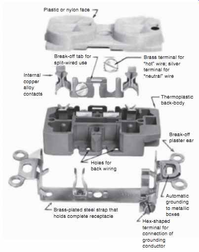
Break-off plaster ear, Automatic grounding to metallic boxes, Hidden from view is the green hexagon screw to attach the grounding wire, Grounding slot, Wide slot for grounded “neutral” wire, Ampere rating, 15 A Voltage rating, 125 V Silver-colored terminals for grounded “neutral” wire, Underwriters Laboratories label -- Hidden from view are the back-wire holes for back-wiring, Narrow slot for ungrounded “hot” wire Break-off tab for split-wired use -- Brass colored terminal for “hot” wire Canadian Standards Association logo
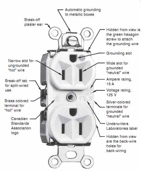
FGR. 3 Grounding-type receptacle detailing various parts of the receptacle.
===
CONNECTING WIRING DEVICES
Terminating and splicing conductors is a skill. The connections must be tight so as not to overheat under load.
NEC 110.3(B) requires us to follow the manufacturers' instructions regarding the listing and labeling of all electrical products. NEC 110.14 provides clear requirements for making electrical connections.
Table 4 shows in detail the terminal identification markings found on wiring devices (switches and receptacles) indicating the types of conductors permitted to be connected to them.
Most commonly used wiring devices have screw terminals.
Some wiring devices have back-wiring holes only. For these, the conductor insulation is stripped off for the desired length, inserted into the hole, and held in place by the device's internal spring pressure mechanism. These wiring devices are referred to as having push-in terminals.
For convenience, some wiring devices have both screw terminals and back-wiring holes, as illustrated in Fgrs. 3 and 4. These can be connected or hooked up in different ways. One way is if the conductor insulation is stripped off for the desired length and inserted into the back hole, and then the screw terminal is properly tightened. In another way, the conductor insulation is stripped off for the desired length and terminated under the screw terminal, in which case the back-wiring holes are not used.
Using both the back-wiring terminals and the screw terminals, it would be possible to terminate as many as four conductors to the white terminal, and four conductors to the brass terminal. This is a violation of 110.3(B). UL does not test receptacles with so many conductors connected to the device.
A much better way is shown in Fgr. 5, where all of the necessary splicing is done independent of the receptacle. Short lengths of wire called pigtails are included in the splice, and these pigtails in turn connect to the receptacle. Removal of the receptacle would not have any effect on the splice.
===
FGR. 4 Exploded view of a grounding type receptacle, showing all internal
parts. 200.10(B) requires that terminals on receptacles, plugs, and connectors
that are intended for the ground-circuit conductor be substantially white (usually
silver colored) or marked with the word "white" or the letter "W" adjacent
to the terminal. The terminal for the ungrounded "hot" conductor
is usually brass colored.
Plastic or nylon face Break-off tab for split-wired use Brass terminal for “hot” wire; silver terminal for “neutral” wire Internal copper alloy contacts Thermoplastic back-body Break-off plaster ear Holes for back wiring Brass-plated steel strap that holds complete receptacle Automatic grounding to metallic boxes Hex-shaped terminal for connection of grounding conductor
===
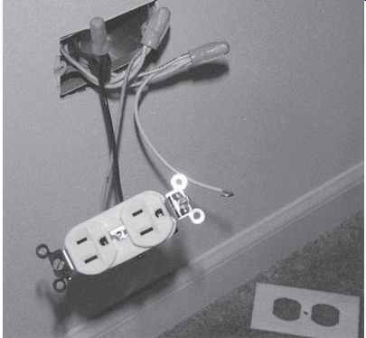
FGR. 5 A receptacle connected with pigtails. This particular installation
has one receptacle switched and one receptacle on continuously. In some areas
this is referred to as a "split-wired receptacle," and as a "switched
receptacle" in other areas. Six conductors enter the box because the wiring
runs from receptacle to receptacle around the room.
A 4-in. square outlet box trimmed with a single-gang plaster (drywall) cover is used.
Removal of the receptacle does not affect the circuit to the other receptacles.
===
Installing Switches and Receptacles
Always make sure that the yokes of switches and receptacles are rigidly held in place so they do not twist. Not tightly securing wiring devices is unsafe as well as being an example of sloppy workmanship, 406.4(A).
Receptacle Configuration
Fgr. 6 illustrates some of the common receptacle configurations used in homes in conformance to Table 210.21(B)(3). Range and dryer receptacles are discussed in Section 20.
===
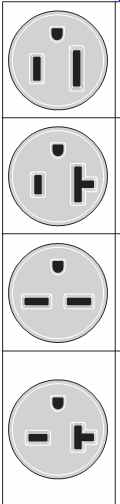
FGR. 6 Slot configuration of receptacles.
Receptacles have the suffix "R" and plug caps have the suffix "P."
A 15-ampere, 125-volt, NEMA 5-15R receptacle.
Short slot: “hot” conductor.
Long slot: grounded conductor.
Horseshoe slot: equipment grounding conductor.
A 15-ampere, 250-volt, NEMA 6-15R receptacle. Slot arrangement will not accept standard 125-volt attachment plug cap; could be used for a 240-volt window air conditioner.
Short slots: “hot” conductors.
Horseshoe slot: equipment grounding conductor.
A 20-ampere, 250-volt, NEMA 6-20R receptacle. Slot arrangement will not accept standard 125-volt attachment plug cap; could be used for a 240-volt window air conditioner. Accepts a 250-volt, 15- or 20-ampere attachment plug.
Short slot: “hot” conductor.
"T" slot: “hot” conductor.
Horseshoe slot: equipment grounding conductor.
A 20-ampere, 125-volt, NEMA 5-20R receptacle. Accepts a 125-volt, 15- or 20-ampere attachment plug.
Short slot: “hot” conductor.
Long "T" slot: grounded conductor.
Horseshoe slot: equipment grounding conductor.
===
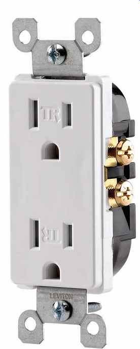
FGR. 7 A typical duplex tamper-resistant receptacle. (Leviton Manufacturing)
===
PUSH-IN TERMINATIONS
Be careful when using screwless push-in terminals.
Screwless push-in terminals on receptacles are listed by Underwriters Laboratories (UL) for use only with solid 14 AWG copper conductors. They are not to be used with:
• aluminum or copper-clad aluminum conductors.
• stranded conductors.
• 12 AWG conductors. By design, the holes are large enough to take only a 14 AWG solid conductor.
Push-in terminals for 12 AWG solid copper conductors are still permitted on snap switches.
Fgr. 7 shows a typical tamper-resistant receptacle. These receptacles are required in most every location in a single-family dwelling. They were introduced into the NEC in an attempt to reduce the number of injuries caused by children who insert foreign objects into these receptacles. Electric shock and burn injuries commonly result when metallic foreign objects make contact with energized terminals in these receptacles.
The general rule in 406.12 is all nonlocking type, 125-volt, 15- and 20-ampere receptacles are required to be tamper-resistant for new installations in dwelling units in all areas specified in 210.52. If you take a look at that section, you will find it literally covers all locations in a dwelling including living areas, garages, unfinished basements, and accessory buildings. Scan through 210.52 and refresh your memory on the areas where tamper-resistant receptacles are required.
Several exceptions apply and exclude:
1. receptacles located more than 5 1/2 ft (1.7 m) above the floor.
2. receptacles that are part of a luminaire or appliance.
3. a single receptacle or a duplex receptacle for two appliances located within dedicated space for each appliance that in normal use is not easily moved from one place to another and that is cord-and-plug connected in accordance with 400.7(A)(6), (A)(7), or (A)(8).
4. Non-grounding receptacles used for replacements as permitted in 406.4(D)(2)(a).
Existing receptacles that are replaced in locations where tamper-resistant receptacles are now required must be replaced with tamper-resistant receptacles; see 406.4(D)(5).
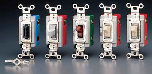
FGR. 8 Toggle switches. (Hubbell Lighting Outdoor & Industrial )
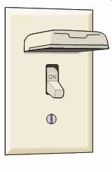
FGR. 9 Switch is protected by a weatherproof cover.
TOGGLE SWITCHES (ARTICLE 404)
UL refers to them as "snap switches." Manufacturers and electricians refer to them as "toggle switches." They are one and the same.
The most frequently used switch in lighting circuits is the flush toggle switch, Fgr. 8. When mounted in a flush switch box, the switch is concealed in the wall, with only the insulated handle or toggle protruding through the cover plate.
Fgr. 9 shows one of the ways switches can be weatherproofed.
Toggle Switch Ratings
UL lists toggle switches used for lighting circuits as general-use snap switches. The UL requirements are the same as 404.14(A) and (B) of the NEC.
AC/DC General-Use Snap Switches [404.14(B)]
The requirements for general-use snap switches include the following:
• Alternating-current (ac) or direct-current (dc) circuits
• Resistive loads not to exceed the ampere rating of the switch at applied voltage
• Inductive loads not to exceed one-half the ampere rating of the switch at applied voltage
• Motor loads not to exceed the ampere rating of the switch at applied voltage only if the switch is marked in horsepower
• Tungsten filament lamp loads not to exceed the ampere rating of the switch at applied voltage when marked with the letter "T"
• For switches marked with a horsepower rating, a motor load not to exceed the rating of the switch at rated voltage.
Why a "T" Rating?
A tungsten filament lamp draws a very high momentary inrush current at the instant the circuit is energized. This is because the cold resistance of tungsten is very low. For instance, the cold resistance of a typical 100-watt lamp is approximately 9.5 ohms. This same lamp has a hot resistance of 144 ohms when operating at 100% of its rated voltage.
Normal operating current would be: 0.83 ampere
The instantaneous inrush current could be as high as: 17.9 amperes
This instantaneous inrush current drops off to normal operating current in about 6 cycles (0.10 second). The contacts of T-rated switches are designed to handle these momentary high inrush currents.
See Section 13 for more information pertaining to inrush currents.
The ac/dc general-use snap switch normally is not marked ac/dc. However, it is always marked with the current and voltage rating, such as 10A-125V or 5A-250V-T.
AC General-Use Snap Switches [404.14(A)]
This is the type most commonly used for house wiring projects. Alternating-current general use snap switches are marked "ac only," in addition to identifying their current and voltage ratings. A typical switch marking is 15A, 120-277V ac. The 277-volt rating is required on 277/480-volt systems.
Other requirements include these:
• Alternating-current (ac) circuits only are allowed.
• Resistive and inductive loads are not to exceed the ampere rating of the switch at the voltage involved. This includes electric-discharge lamps that involve ballasts, such as fluorescent lamps.
• Tungsten-filament lamp loads are not to exceed the ampere rating of the switch at 120 volts.
• Motor loads are not to exceed 80% of the ampere rating of the switch at rated voltage. A UL requirement is that the load shall not exceed 2 horsepower.
What Are the Switching Conductors Called?
In 200.7(C)(1), we find a few unique words that have to be explained. There are also local and regional expressions for these words. It is always best to use the terms found in the NEC.
• Switch loop: The conductors that run between (to and from) a switched outlet and the switch controlling that outlet.
• Supply: The conductor that runs from the source to the switch. It might also be referred to as the feed, hot, hot leg, or supply leg.
Lamp Source Switch, loop S
• Return: The conductor that runs from the switch back to the switched outlet. It might also be referred to as the switch leg or switched leg.
Conductor Color Coding for Switch Connections
The insulated conductors in nonmetallic sheathed cable or armored cable that are commonly used for switching functions are typically black-white, black-white-red, or, in some cases, black-white-red-blue. We usually think of the black insulated conductor as the supply to a switch and a red insulated conductor as the return. However, when wiring with nonmetallic-sheathed cable or armored cable, we are "stuck" with the colors found in the cables. We must not use a white conductor as the return conductor from a switch, 200.7(C)(1). A color-coding scheme must be established for the supplies and returns. In the case of 3-way and 4-way switches, we also have "travelers"-the conductors that connect between 3-way and 4-way switches.
The wiring diagrams in Fgrs. 11 through 22 show the recommended color schemes when wiring with cable.
Do You Need the Grounded Circuit Conductor at the Switch?
Maybe yes; maybe no.
Conventional switches operate on a mechanical principle and are simply connected "in series" with the load. The contacts of the switch close (on) and open (off). This type of switch does not require a grounded circuit conductor to operate correctly.
However, a new requirement was added to the 2011 edition of the NEC in 404.2(C). The rule requires, Where switches control lighting loads supplied by a grounded general purpose branch circuit, the grounded circuit conductor for the controlled lighting circuit shall be provided at the switch location.* This rule applies irrespective of the wiring method used or whether the switches are single-pole, 3-way, or 4-way.
Two exceptions are provided. The first applies to wiring methods such as EMT. It allows, (1) A grounded circuit conductor is not required if the conductors for the switches that control lighting loads enter the box through a raceway so long as the raceway has sufficient cross-sectional area to accommodate the extension of the grounded circuit conductor of the lighting circuit to the switch location even if the conductors in the race way are required to be increased in size to comply with 310.15(B)(3)(a).
* A second exception applies to cable-type wiring methods and provides, A grounded circuit conductor is not required so long as the cable assemblies for switches controlling lighting loads enter the box through a framing cavity that is open at the top or bottom on the same floor level, or through a wall, floor, or ceiling that is unfinished on one side.
* The Informational Note tells us the purpose of the neutral conductor is to complete a circuit path for electronic lighting control devices.
The result of this rule requires a 3-wire cable to most single-pole switches if the source is at the lighting outlet-one supply conductor to the switch, one return conductor, and the neutral. This is shown in Fgr. 13.
For 3-way and 4-way switch loops, the number of conductors varies according to which end of the switches the supply is connected to. If the sup ply is at the furthest 3-way switch from the lighting outlet, three conductors are required between switches, as shown in Fgr. 21. This shows compliance with the new rule, as a neutral is avail able at each switch box. If the supply starts at the lighting outlet, the installation is more complicated and expensive. To provide a neutral at every switch location, a 3-wire cable is required from the lighting outlet to the first 3-way switch and a 4-wire cable between the 3-way switches. This is shown in Fgr. 22.
If the dwelling is wired with EMT, the electrician will have to be certain there is space for the neutral to be pulled into the EMT. The exception to the rule for EMT wiring includes the requirement to preplan for derating, because there are more than three current-carrying conductors in the raceway.
Electronic control devices such as dimmers, motion sensors, occupational sensors, photoelectric devices, timers, and fan speed controls must have a small voltage drop across them to operate.
This type of switch (control) must have both the grounded and ungrounded circuit conductors connected to it.
Recently introduced to the marketplace are listed wiring devices such as occupancy sensors that have internal electronic circuitry that allow a maximum of 0.5 milliampere (mA) "leakage" to ground. This tiny amount of "leakage" current is enough to power up the electronic circuitry in the device, yet does not pose a shock hazard. This is referred to as low-level standby current. The maxi mum leakage current of 0.5 mA is the same value of leakage current permitted for electric appliances. These devices will have a white conductor that is connected to the neutral provided in the switch box.
Illuminated toggle switches, rocker switches, and illuminated faceplates do not require the grounded circuit conductor. These are merely "in series" with the load. Their operation is load "ON," pilot lamp "OFF"; or load "OFF," pilot lamp "ON." See Fgr. 25.
True pilot lights require the grounded circuit conductor. Their operation is load "ON," pilot lamp "ON"; or load "OFF," pilot lamp "OFF." See Fgr. 27.
What To Do? Most decisions on how the switching run is installed are made on an installed-cost basis.
The electrician or electrical contractor will need to look at the actual layout on the job to determine the most economical approach based on the cost of labor and materials. The most economical installation may be to always connect the supply at the switch. The two methods are shown in Fgrs. 12 and 17.
Never use the equipment grounding conductor as a substitute for the circuit's grounded or neutral conductor. This could prove to be deadly.
When the wiring method is a raceway or electrical metallic tubing (EMT), the choices of insulation colors are virtually unlimited.
Always connect a white wire to the white (silverish) terminal or to the white wire of a lampholder or receptacle, 200.9 and 200.10. Always connect the black switch leg conductor (or red in some cases) to the black wire (or dark brassy terminal) of a lamp holder or receptacle.
Because the neutral is required at the switch box, the need to re-identify conductors as neutrals in 2-, 3-, and 4-wire cables used for switching functions has practically been eliminated.
Never use a green-colored insulation for a grounded or ungrounded conductor. Green is reserved for equipment grounding conductors. See 210.5 and 250.119. See Table 2.
Prev. | Next
Similar Articles