AMAZON multi-meters discounts AMAZON oscilloscope discounts
OBJECTIVES
• understand some of the safety issues concerning optional standby power systems.
• understand the basics of standby power.
• understand the types of standby power systems.
• understand wiring diagrams for portable and standby power systems.
• understand transfer switches, disconnecting means, and sizing recommendations.
• understand the National Electric Code requirements for standby power systems.
The text that follows is a general discussion and overview of home-type temporary generator systems.
It is not possible in this section to cover all the variables and details involved with the many types of standby power systems available in the market place today.
WARNING: Exhaust gases contain deadly carbon monoxide, the same as an automobile engine.
One 5.5-kilowatt generator produces as much carbon monoxide as six idling automobiles. Carbon monoxide can cause severe nausea, fainting, or death. It is particularly dangerous because it is an odorless, colorless, tasteless, nonirritating gas. Typical symptoms of carbon monoxide poisoning are dizziness, headache, light-headedness, vomiting, stomachache, blurred vision, and inability to speak clearly. If you suspect carbon monoxide poisoning, remain active.
Do not sit down, lie down, or fall asleep. Breathe fresh air-fast!
Precautions to Follow When Operating a Generator
• Always install equipment such as generators, power inlets, transfer switches, and panelboards that are listed by a nationally recognized testing laboratory (NRTL).
• Always carefully read, understand, and follow the manufacturer's installation instructions.
• Always turn off the power when hooking up standby systems. Do not work on "live" equipment.
• Do not stand in water or otherwise work on electrical equipment with wet hands.
• Do not touch bare wires.
• Store gasoline only in approved red containers clearly marked "GASOLINE."
• Do not operate indoors.
• Do not operate in the garage.
• Operate a portable generator only outside in open air, not close to windows, doors, or other vents. Exhaust fumes from the generator can infiltrate the house or a neighbor's house.
• Death is just around the corner when the above warnings are not heeded!
WHY STANDBY (TEMPORARY) POWER?
Everyone has experienced a power outage, some times more often than one would like. You are left in the dark. Your furnace does not operate. You are concerned about water pipes freezing in the winter.
Your refrigerator and freezer are not running. Your sump pump is not operating, and your basement is flooding. Your overhead garage door does not operate. You want the peace of mind that the essential equipment and appliances will continue to function while you are on an extended trip. Or, possibly worst of all, you may miss the most important sports game of the year on TV!
What can you do? The Y2K crisis made every one aware of the consequences of a major power outage. Generators were carried out of home centers and other dealers at a furious pace. Now that the supposed Y2K crisis is history, it still makes sense to consider a standby power system.
A few questions have to be answered. In your home, which loads are critical and must continue to operate in the event of a utility power outage? You need to know this so you can select a generator panelboard with adequate space for branch circuits. Only you can make this decision. Another question that must be answered is, how large must the generator be to serve the loads that are considered critical in your home? Still another question is, how simple or complicated a standby system do you want?
WHAT TYPES OF STANDBY POWER SYSTEMS ARE AVAILABLE?
The Simplest
Home centers usually carry the simplest and most economical portable generators, as shown in FIG. 1. These consist of a gasoline-driven motor/ generator set that must be started manually. Some models have the recoil "pull-to-start" feature; others have battery electric start. These are the types construction workers use for temporary power on job sites. Depending on the size of the fuel tank and the load being sup plied, these smaller generators might be capable of running for 4 to 8 hours. This type of portable genera tor is commonly referred to as "backup" power.
These small portable generators consist of a gasoline engine driving a small electrical generator, just like a gasoline engine drives the blades of a lawn mower or snow thrower. Some generator sets have one or more standard 15- or 20-ampere single or duplex grounding-type receptacles, some have GFCI receptacles, and others have 20- and 30-ampere twistlock-type receptacles. Some are rated 120 volts, whereas others are rated 120/240 volts.
These generators are available in sizes up to about 7000 watts. Also available are models with more "bells and whistles" such as oil alerts, adjust able output voltage, larger fuel tanks, and so on.
The procedure for this type is to start up the generator, then plug an extension cord into the receptacle and run it to whatever critical cord-and-plug- connected load needs to operate.
If you are not home when a power outage occurs, you are out of luck!
====
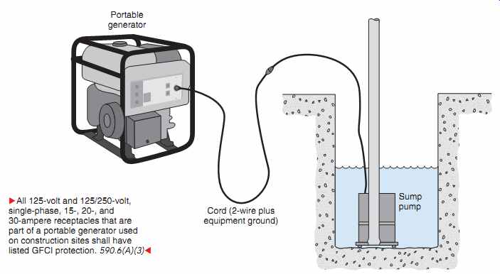
FIG. 1 A portable generator serving standby power to a 120-volt sump
pump.
Portable generator Sump pump Cord (2-wire plus equipment ground)
All 125-volt and 125/250-volt, single-phase, 15-, 20-, and 30-ampere receptacles that are part of a portable generator used on construction sites shall have listed GFCI protection. 590.6(A)(3)
====
Receptacles on Portable Generator Sets
Because of the extreme hazards always present for workers on construction sites, particularly when using portable generators for temporary power, NEC 590.6(A)(3) requires that All 125 volt and 125/250 volt, single-phase, 15-, 20-, and 30 ampere receptacle outlets that are a part of a 15 kW or smaller portable generator shall have listed ground fault circuit interrupter protection for personnel.* The requirements of Article 590 apply to Temporary Wiring and clearly cover construction sites.
CAUTION: Electricity from generators can also cause electric shock when used at dwellings.
Purchase a generator that has GFCI protection. For existing generators without GFCI protection, use a listed portable cord that has GFCI protection.
====
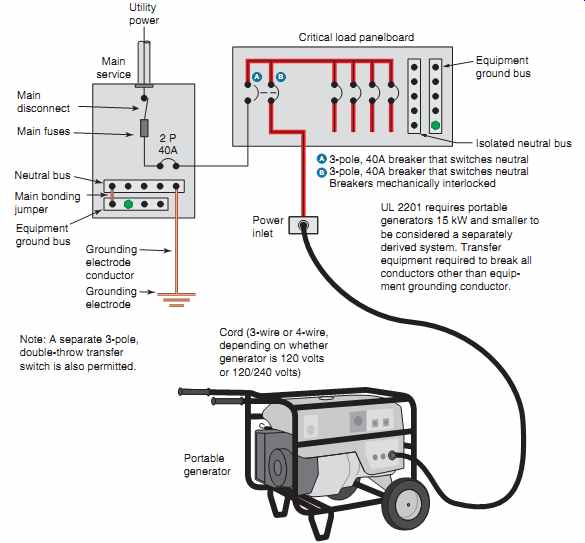
FIG. 2 A portable generator supplies standby power to a critical load
panelboard. The circuit breakers in the critical load panelboard must be manually
turned to the temporary power position. These breakers are equipped with a
mechanical interlock so there will be no feedback of electricity between the
generator power and the utility normal power.
2 P 40A Grounding electrode conductor Grounding electrode Main service Utility power Main disconnect 3-pole, 40A breaker that switches neutral 3-pole, 40A breaker that switches neutral Breakers mechanically interlocked Equipment ground bus Isolated neutral bus Power inlet
Portable generator ;Cord (3-wire or 4-wire, depending on whether generator is 120 volts or 120/240 volts) Main fuses Neutral bus Main bonding jumper Equipment ground bus Critical load panelboard A B A B UL 2201 requires portable generators 15 kW and smaller to be considered a separately derived system. Transfer equipment required to break all conductors other than equipment grounding conductor.
Note: A separate 3-pole, double-throw transfer switch is also permitted.
====
The Next Step Up
The next step up involves both permanent wiring and cord-and-plug-connected wiring.
This is by far the most popular when it comes to standby power for homes. In the event of a power outage, you must manually start the generator, flip the transfer switching device over from normal power to standby power, and plug in the power "patch" cord (FIG. 2).
The permanent wiring part of the installation involves connecting specific branch circuits to a separate generator panelboard (usually located right next to the main panelboard), installing and properly connecting a transfer switch (discussed later), and installing a power inlet receptacle (discussed later). The generator panelboard serves those circuits that you have selected as critical to operate in the event of a power outage. This panelboard is sometimes referred to as a generator panelboard, a selected load panelboard, an emergency panelboard (these systems in dwellings almost never meet the definition of an emergency system in NEC 700.2), and sometimes a critical load panelboard (FIG. 3).
The cord-and-plug-connected part of the installation consists of merely a flexible power patch cord that runs between the generator and the power inlet receptacle. This cord and the generator are set up as needed.
These are gasoline-powered generators that use a flexible 4-wire rubber cord (12 AWG for 5000-watt generators, 10 AWG for 7500-watt generators) that plugs into a female polarized twistlock receptacle on the generator. The other end of the cord plugs into a polarized twistlock receptacle mounted on the out side of the house in a weatherproof power inlet box.
This polarized twistlock receptacle is permanently connected to transfer equipment or to a special electrical generator panelboard in which the critical branch circuits are connected. The generator panelboard will have a transfer mechanism plus from 4 to 20 branch-circuit breakers; it all depends on the wattage rating of the generator. Some generator panelboards have the polarized twistlock receptacle mounted as part of and just below the generator panelboard.
===
2 P 40A Grounding electrode conductor Grounding electrode Main service Utility power Main disconnect 3-pole, 40A breaker that switches neutral 3-pole, 40A breaker that switches neutral Breakers mechanically interlocked Equipment ground bus Isolated neutral bus Power inlet
Portable generator Cord (3-wire or 4-wire, depending on whether generator is 120 volts or 120/240 volts)
Main fuses Neutral bus Main bonding jumper Equipment ground bus Critical load panelboard A B A B UL 2201 requires portable generators 15 kW and smaller to be considered a separately derived system. Transfer equipment required to break all conductors other than equipment grounding conductor.
Note: A separate 3-pole, double-throw transfer switch is also permitted.
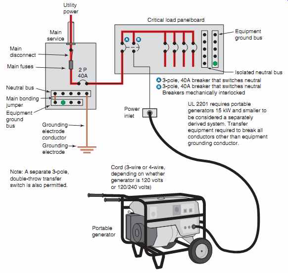
FIG. 3 A critical load panelboard served by normal power from the main
service panelboard.
A portable generator is shown plugged into the power inlet. To switch to standby power, the circuit breakers in the critical load panelboard must be manually turned to the standby position. These breakers are equipped with a mechanical interlock so there will be no feedback of electricity between the generator power and the utility normal power.
===
During normal operation, this generator panel board is fed from a 2-pole circuit breaker in the main panelboard. This 2-pole breaker might be rated 30, 40, 50, or 60 amperes, depending on the number of critical branch circuits to be supplied.
When utility power is lost, this generator panel board is fed from the generator. When the electric utility loses power, you must manually turn the "transfer switch" from its normal power position to its temporary power position. One manufacturer of electrical equipment furnishes a panelboard that contains two circuit breakers that are mechanically interlocked. These are required to be 3-pole breakers because the neutral from a portable generator must be switched. These breakers serve as the transfer switching means. Only one breaker can be in the "On" position at the same time. One of these breakers brings the normal power to the generator panelboard. The second breaker brings the power from the generator to the generator panel board. When one breaker is turned "Off," the other is turned "On." This panelboard will have four or more branch-circuit breakers.
With this system, the procedure generally is to first plug the 4-wire cord into the polarized twistlock receptacle on the generator; plug the other end into the power inlet receptacle; and then start the genera tor, which is always located outdoors. The transfer switch in the generator panelboard is then switched to the "GEN" position.
When normal power is restored, turn the transfer switch in the generator panelboard back to its normal position; turn off the generator according to the manufacturer's instructions; unplug the power cord from the generator; and finally, unplug the other end of the cord from the power inlet receptacle.
UL Standard Requirements
The UL Safety Standard UL 2201 is titled,
''Portable Engine-Generator Assemblies.'' This standard covers portable generators that are rated up to 15 kW. The guide card information for the standard in the UL White Book in category "Engine Generators for Portable Use (FTCN)" reads,
"This category covers internal-combustion engine-driven generators rated 15 kW or less, 250 V or less, which are provided only with receptacle outlets for the ac output circuits.
The generators may incorporate alternating- or direct-current generator sections for sup plying energy to battery-charging circuits.
When a portable generator is used to supply a building wiring system:
1. The generator is considered a separately derived system in accordance with ANSI/NFPA 70, National Electrical Code (NEC).
2. The generator is intended to be connected through permanently installed Listed transfer equipment that switches all conductors other than the equipment grounding conductor.
3. The frame of a listed generator is connected to the equipment grounding conductor and the grounded (neutral) conductor of the generator. When properly connected to a premises or structure, the portable generator will be connected to the premises or structure grounding electrode for its ground reference.
4. Portable generators used other than to power building structures are intended to be connected to ground in accordance with the NEC.*" The safety standard adds to or supplements requirements in the NEC. Let's look at these rules one by one.
1. "The generator is considered a separately derived system in accordance with ANSI/NFPA 70, National Electrical Code (NEC)." The term separately derived system as defined in NEC Article 100 means that the transfer equipment must break all system conductors from the generator, including the neutral.
This rule is in place to prevent the equipment grounding conductor from being in parallel with the neutral and carrying neutral current.
Normally, this rule would require the genera tor to be grounded at the source. The NEC has special rules for grounding portable generator electrical systems in NEC 250.34. See our discussion following list item 4.
2. "The generator is intended to be connected through permanently installed Listed transfer equipment that switches all conductors other than the equipment grounding conductor." The installation of transfer equipment that switches all conductors, including the grounded or neutral conductor, is the deciding factor in deter mining that the system is in fact a separately derived system. Once again, separately derived systems are generally required to have the neutral grounded (connected to earth) at the source.
This is not the case for portable generators. See our discussion following list item 4.
3. "The frame of a Listed generator is connected to the equipment-grounding conductor and the grounded (neutral) conductor of the generator.
When properly connected to a premises or structure, the portable generator will be connected to the premises or structure grounding electrode for its ground reference." These connections ensure that a ground-fault return path is established back to the source, which is the generator winding. Be very cautious when selecting a generator. Some manufacturers produce generators with a floating neutral.
As a result, it is impossible for an overcurrent device to operate on a ground fault because no circuit for fault current can be established.
The connection of the neutral and equipment grounding conductor to the frame of the generator is required in NEC 250.34(A)(2) and (C).
4. "Portable generators used other than to power building structures are intended to be connected to ground in accordance with the NEC." This sentence might better be read "Portable generators used other than to power building structures are intended to be connected to ground (grounded) if required by the NEC." The NEC contains special requirements for grounding of portable generators in 250.34.
So long as the generator supplies loads only through receptacles mounted on the genera tor and the equipment grounding conductor is connected to the generator frame, the frame of the portable generator is not required to be connected to a grounding electrode.
When connected to the service-supplied electrical system by cord-and-plug connection, the equipment grounding conductor serves as a ground or earth reference for the electrical system because the conductor is extended to the windings of the generator.
Important: If you intend to have a GFCI breaker-protected branch circuit transferred to the generator panelboard, be sure to connect this circuit to a GFCI breaker in the generator panelboard.
Because GFCIs and AFCIs require a neutral conductor, make sure the neutral conductor is properly connected between the main panelboard neutral bus and the neutral bus in the critical panelboard.
The neutral bus in the generator panelboard is insulated from the generator panelboard enclosure.
The ground bus in the generator panelboard is bonded to the generator panelboard enclosure.
Standby generators of this type can have run times as long as 16 hours. Again, it depends on the loading. The manufacturer's installation and operating instructions will provide this information.
If you are not home when the power outage occurs, you are out of luck! The Top of The Line
Standby power served by a permanently installed generator is truly standby power. These types of generator systems are covered under UL Standard 2200, Stationary Engine Generator Assemblies.
Standby power is a system that allows you to safely provide electrical power to your home in the event of a power outage. Instead of running extension cords from a portable generator located out side of the house to whatever critical loads (lights, sump pumps, refrigerators, etc.), you select the branch- circuits you feel are critical or essential to satisfactorily operate your home electrical system.
These branch circuits are placed in a panelboard that will be transferred to the generator in the event of a power outage from the electric utility. The diagrams in this section show this.
The generator for this type of system is permanently installed on a concrete pad at a suitable location outside of the home, convenient to making up all of the electrical connections to serve the selected critical loads. These systems generally run on natural gas (FIG. 4) or propane (liquid petroleum gas-LPG), and in rare cases, on diesel fuel. All the conductors between the generator, the transfer switch, and the generator panelboard installed for the selected critical loads are permanently wired.
Note than the power conductors and control conductors are installed in separate raceways to satisfy the requirements in NEC 725.136.
The automatic transfer switch monitors the incoming electric utility's voltage. Should a power outage occur, the standby generator automatically starts, the transfer switch "transfers," and the selected loads continue to function. When normal power is restored, the transfer switch automatically "transfers" back to the normal power source, and the generator shuts down.
Because the fuel supply is a permanently installed natural gas line, these systems can run indefinitely in conformance to the manufacturer's specifications.
To be totally automatic, an electronic controller that is part of the transfer switch immediately senses the loss of normal power and "tells" the standby generator to start, and to "tell" the transfer switch to transfer from normal power to standby power. This controller senses when normal power is restored, allowing the transfer switch to return to normal power and to shut off the standby generator. All of the circuitry is reset, and it is now ready for the next power interruption.
WIRING DIAGRAMS FOR A TYPICAL STANDBY GENERATOR
For simplicity, the diagrams in FIGs. 5 and 6 are one-line diagrams. Actual wiring consists of two ungrounded conductors and one grounded "neutral" conductor. Equipment grounding of all of the components is accomplished through the metal raceways that interconnect the components. See 250.118.
The neutral bus in a panelboard that serves selected loads must not be connected to the metal panelboard enclosure. Connecting the neutral conductor, the grounding electrode conductor, and the equipment grounding conductors together is permit ted only in the main service panelboard.
If you were to bond the neutral conductor and the metal enclosures of the equipment (panelboard, transfer switch, and generator) together beyond the main service panelboard, you would create a parallel path. A parallel path means that some of the normal return current and fault cur rent will flow on the grounded neutral conductor and some will flow on the metal raceways and other enclosures. This is not a good situation! See NEC 250.6 and 250.24(A)(5).
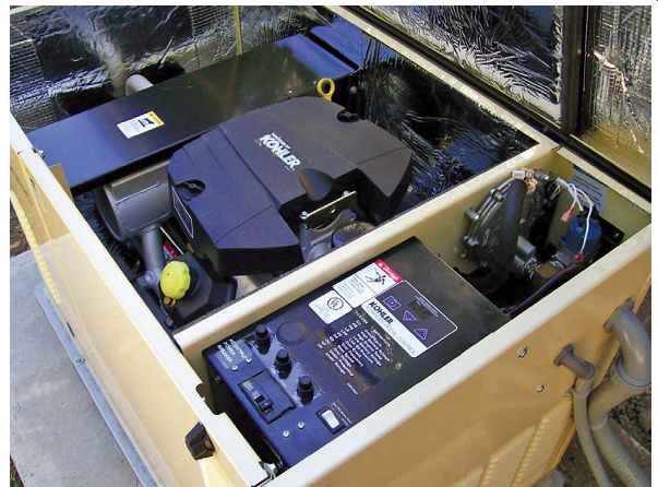
FIG. 4 A natural gas-fueled generator. (Kohler Power Systems)
Manufacturers of generators in most cases do not connect the generator neutral conductor lead to the metal frame of the generator. Instead, they connect it to an isolated terminal. Then it is up to you to determine how to connect the generator in compliance with the NEC and/or local electrical codes.
Most inspectors will permit the internal neutral bond in a portable generator to remain in place. In fact, when you purchase a portable generator, you should insist the neutral-to-case bond is in place.
Without the bond, an overcurrent device cannot function on a ground fault because a return path does not exist. For permanently installed generators, inspectors will generally not permit a bond between the generator neutral and the metal frame of the generator because of the explicit requirements in the NEC.
A sign must be placed at the service-entrance main panelboard indicating where the standby generator is located and what type of standby power it is. See 702.8(A).
The total time for complete transfer to standby power is approximately 45-60 seconds.
To further give the homeowner assurance that the standby generator will operate when called upon, some systems provide automatic "exercising" of the system periodically, such as once every 7 or 14 days for a run time of 7 to 15 minutes.
====
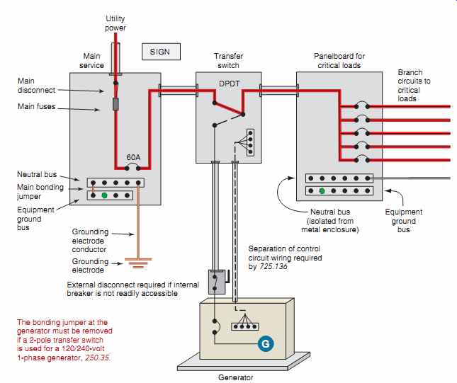
FIG. 5 A natural gas-driven generator connected through a transfer switch.
The transfer switch is in the normal power position. Power to the critical
load panelboard is through the main service panelboard, then through the transfer
switch.
====
WARNING: When an automatic type of standby power system is in place and set in the automatic mode, the engine may crank and start at any time without warning. This would occur when the utility power supply is lost. To prevent possible injury, be alert, aware, and very careful when working on the standby generator equipment or on the transfer switch. Always turn the generator disconnect to the "Off" position, then lock out and tag out the switch, warning others not to turn the switch back "On." In the main panelboard, locate the circuit breaker that supplies the transfer equipment, turn it "Off," then lock out and tag out the circuit breaker feeding the transfer switch.
===
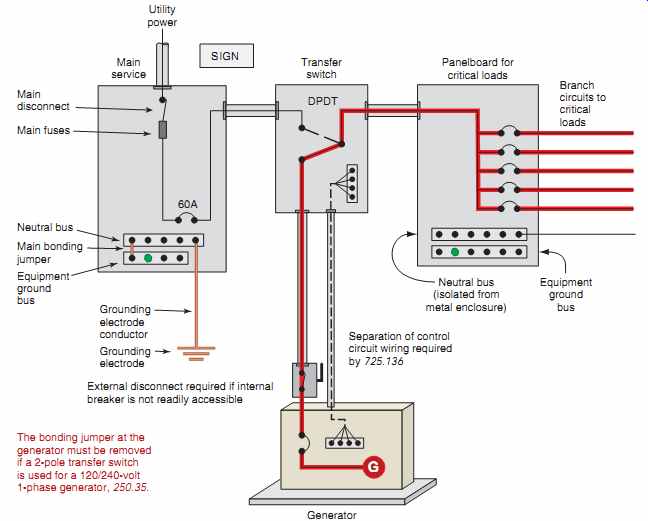
FIG. 6 A natural gas-driven generator connected through a transfer switch.
The transfer switch is in the standby position, feeding power to the critical load panelboard. Neutral bus (isolated from metal enclosure) Equipment ground bus 60A Generator Main service Transfer switch Utility power Main disconnect Main fuses Panelboard for critical loads Branch circuits to critical loads G SIGN DPDT Neutral bus Main bonding jumper Equipment ground bus The bonding jumper at the generator must be removed if a 2-pole transfer switch is used for a 120/240-volt 1-phase generator, 250.35.
Grounding electrode conductor; Grounding electrode; Separation of control circuit wiring required by 725.136; External disconnect required if internal breaker is not readily accessible
===
TRANSFER SWITCHES OR EQUIPMENT
A transfer switch or equipment shifts electrical power from the normal utility power source to the standby power source. A transfer switch isolates the utility source from the standby source in such a way that there is no feedback from the generator to the utility's system, or vice versa. When normal power is restored, the automatic transfer switch resets itself and is ready for the next power outage.
Transfer switches or equipment for typical residential applications might have ratings of 40 to 200 amperes. Some have wattmeters for balancing generator loads.
For home installations, transfer switches may be 3-pole double throw (TPDT) or double-pole, double throw (DPDT), depending on how the type of system is being installed. As stated above for listed portable generators, a 3-pole, double-throw transfer switch or equipment is required.
For permanently installed generators, either a 2-pole or 3-pole transfer switch or equipment is permitted so long as the generator produced electrical system is coordinated with the transfer equipment.
Two-pole transfer switches or equipment do not break the "neutral" conductor of a 120/240 volt single-phase system. Technically speaking, the NEC refers to this type of system as a nonseparately derived system. A nonseparately derived system is properly grounded through the grounding electrode system of the normal premises wiring at the service equipment. A system where the neutral is disconnected by the transfer switch is referred to as a separately derived system and must be regrounded according to 250.30. Separately derived systems are common in commercial and industrial installations and are required for connection of portable generators.
If a transfer switch is connected on the line side of the main service disconnect, it must be listed as being suitable for use as service equipment. In FIGs. 5 and 6, the transfer switch is not on the line side of the main service disconnect and therefore does not have to be listed for use as service equipment.
A transfer switch must "break-before-make." Without the "break-before-make" feature, a dangerous situation is present and could lead to destruction of the generator, personal injury, or death. If the transfer switch does not separate the utility line from the standby power line, utility workers working on the line could be seriously injured. For low cost, nonautomatic transfer systems, the transferring means might consist of two 2-pole or 3-pole circuit breakers that are mechanically interlocked so both cannot be "On" at the same time.
Capacity and Ratings of Transfer Equipment (NEC 702.6) The rating of the transfer switch must be capable of safely handling the load to be served. Otherwise, the transfer switch could get so hot as to cause a fire.
This is nothing new; it is the same hazard as over loading a conductor. Specific rules on the capacity of the generator are dependent on the type of the transfer switch used, as follows:
1. If manual transfer equipment is used, an optional standby system is required to have adequate capacity and rating for the supply of all equipment intended to be operated at one time. The user of the optional standby system is permitted to select the load that is connected to the system.
2. If automatic transfer equipment is used, an optional standby system must comply with parts (a) or (b).
(a) Full Load. The standby source shall be capable of supplying the full load that is transferred by the automatic transfer equipment.
(b) Load Management. If a system is employed that will automatically manage the connected load, the standby source must have a capacity sufficient to supply the maximum load that will be connected by the load management system.
A transfer switch must also be capable of safely interrupting the available fault-current that the generator or utility is capable of delivering. Listed transfer switches or equipment may be provided with or without integral overcurrent protection. The suitability of listed transfer equipment for interrupting or withstanding short-circuit current is marked on the transfer equipment.
A typical transfer switch might take 10 to 15 seconds to start the generator. This eliminates nuisance start-ups during momentary utility power outages.
After start-up, another 10- to 15-second delay is pro vided to allow the voltage to stabilize. After start-up and warm-up, full transfer takes place. Similar time delay features are used for the return to normal power.
Some systems can do the full transfer in a few seconds.
The UL Product Standard is 1008, Transfer Switch Equipment.
See the book Electrical Grounding and Bonding for additional information on grounding and bonding of separately derived and nonseparately derived alternate power systems supplied by generators.
DISCONNECTING MEANS
A disconnecting means is required for a generator. NEC 445.18 states that Generators shall be equipped with disconnect(s), lockable in the open position, by means of which the generator and all protective devices and control apparatus are able to be disconnected entirely from the circuits supplied by the generator except where both of the following conditions apply:
1. The driving means for the generator can be readily shut down
2. The generator is not arranged to operate in parallel with another generator or other source of voltage.*
NEC 225.34 requires that all disconnecting means shall be grouped.
If an outdoor housed generator set is equipped with a readily accessible disconnecting means that is located within sight of the building or structure supplied, and additional disconnecting means is not required where ungrounded ("hot") conductors serve or pass through the building or structure, NEC 702.12. Most electrical inspectors will allow the cord-and-plug connection for a portable generator to serve as the disconnecting means.
Where the normal power main service disconnecting means is located inside of the home, some electrical inspectors will require that a disconnect for the standby power from the generator be installed near the main service equipment.
NEC 225.34(B) states that the required disconnect for the standby generator be located remote from the normal service disconnect. This is to lessen the possibility of accidentally shutting off both disconnects at the same time.
Having one disconnecting means inside the home and another outside of the home presents quite a challenge for firefighters or others wanting to totally shut off the power to the home. This is why NEC 702.9(A) requires that a sign be placed at the service-entrance equipment that indicates the type and location of on-site optional standby power sources.
GROUNDING
Grounding the metal frame of a portable generator is through the equipment grounding conductor in the power cord. Grounding of a hard-wired generator is accomplished by means of a metallic wiring method or other means acceptable by 250.118.
It is not necessary to connect the frame of a portable generator to a grounding electrode, 250.34(A).
CONDUCTOR SIZE FROM STANDBY GENERATOR
The conductors that run from the standby generator to the transfer switch and to the generator panel board that contains the branch-circuit overcurrent devices shall be sized not less than 115 percent of the generator's nameplate current rating. See NEC 445.13. This applies if overcurrent protection of the conductors is not provided at the generator source.
If the generator is equipped with an overcurrent device, the standard rules for sizing conductors in NEC 240.4 apply.
In the 608C column of Table 310.15(B)(16), we find that an 8 AWG copper conductor has an allow able ampacity of 40 amperes. The discussion on when to use the 608C and when to use the 758C columns of NEC Table 310.15(B)(16) is covered in Section 4.
The neutral conductor is permitted to be sized according to 220.61, which under certain conditions allows the neutral conductor to be smaller than the phase conductors. This information is found in NEC 445.13.
TABLE 1 Wattage ratings of appliances. [not shown]
GENERATOR SIZING RECOMMENDATIONS
No matter what type or brand of generator you purchase, you will have to size it properly. There is no better way to do this than to follow the manufacturer's recommendations. Generators for home use are generally rated in watts. The manufacturer of the generator has taken into consideration that watts 5 volts 3 amperes. Some manufacturers suggest that after adding up all of the loads to be picked up by the generator, add another 20% capacity for future loads.
As stated above, the type of transfer switch installed determines the minimum capacity required for the generator. If a manual transfer switch or equipment is installed, a generator is required to have capacity for all of the equipment intended to be operated at one time. The user of the optional standby system is permitted to select the load connected to the system. See NEC 702.6(B)(1).
If the generator is supplied with an automatic transfer switch or equipment, it is required to be capable of supplying the full load that is transferred by the automatic transfer equipment. A load management system is permitted to be installed, in which case the generator must be sized not smaller than required to supply the maximum load that the load management system will allow for it to be connected to the equipment. See NEC 702.6(B)(2).
Wattage ratings of appliances vary greatly, as shown in Table 32-1. Resistive loads such as toasters, heaters, and lighting do not have an initial high inrush surge of current. Motors, on the other hand, do have a high inrush surge of starting current, which lasts for only a few seconds until the motor gets up to speed. This inrush must be taken into consideration when selecting a generator. Here are some typical approximate values for household loads. For heating-type appliances, the typical operating watt age values are used. For motor-operated appliances, the starting wattage values should be used. Verify actual wattage ratings by checking the nameplate on the appliance. Verify that the connected loads do not exceed the generator's marked capacity.
Most generators are capable of handling a momentary "inrush" of an extra 50% of their rating.
Here again, check the manufacturer's specifications.
THE NATIONAL ELECTRICAL CODE REQUIREMENTS
The NEC addresses optional standby systems in Article 702. This includes those systems that are permanently installed in their entirety, and those systems that are intended for connection to a premises wiring system from a portable alternate power supply.
• NEC 702.6: All of the equipment must have the capacity and rating for the loads that will be supplied by the equipment. The equipment shall be suitable for the maximum available fault current at its terminals.
• NEC 702.7: Transfer equipment shall be suitable for the intended use and designed to prevent the interconnection of the generator and the normal utility supply.
• NEC 702.8: Some systems, where practical, require audible and visual signal devices to indicate when the normal power system has been transferred to the standby system. The manufacturer of the equipment provides these features. Signal devices are not required for portable standby generators, 702.8, Exception.
• NEC 702.9(A): A sign is required at the service entrance equipment to indicate the type and location of the standby generator.
• NEC 702.9(B): Where the grounded circuit conductor connected to the optional standby generator is connected to a grounding electrode conductor at a location remote from the standby source, there shall be a sign at the grounding location that shall identify all standby and normal sources connected at that location. For most residential standby systems, this connection is made on the neutral bus in the generator panelboard. This neutral bus in turn has a conductor run to the neutral bus in the main panelboard, where the neutral bus and equipment grounding bus are connected together, and a grounding electrode conductor is connected and run to the grounding electrode of the system. The neutral bus in the genera tor panelboard is isolated from the panelboard enclosure. The equipment grounding bus in the generator panelboard is bonded to the panel board enclosure.
• NEC 702.9: It is permissible to run standby power conductors and normal power conductors in the same raceway or enclosure.
• NEC 702.11(B): Where a portable optional standby source is used as a nonseparately derived system, the equipment grounding conductor shall be bonded to the system grounding electrode. The equipment grounding conductor (green or bare) from the standby generator to the generator panelboard is connected to the equipment grounding bus in the generator panelboard. The equipment grounding bus in the generator panelboard is bonded to the generator panelboard enclosure. In turn, the equipment grounding bus in the generator panelboard is bonded back to the main panelboard either by a metallic wiring method, or by a separate equipment grounding conductor. At the main panelboard, the grounding electrode conductor is connected to both the equipment ground bus and the neutral bus.
• NEC 702.12 tells us that if an optional outdoor housed standby system generator is
- equipped with a readily accessible disconnecting means, and
- located within sight of the building it serves, an additional disconnecting means is not required where the ungrounded conductors from the generator serve or pass through the building it serves. See 225.31 and 225.32.
Permits Permanently installed generators require a considerable amount of electrical work and gas line piping. The installation will probably require applying for a permit so that proper inspection by the authorities can be made. Check with your local building official.
Sound Level Because generators produce a certain level of "noise" (decibels) when running, you will want to check with your building authorities to make sure the generator you choose is in compliance with local codes relative to any sound ordinance that might be applicable. Sound-level information is provided by manufacturers in their descriptive literature.
REVIEW
Note: Refer to the Code or the plans where necessary.
1. The basic safety rule when working with electricity is to...
2. Where would the logical location be for running a portable generator?
3. The best advice to follow is to always use (listed) (cheapest) (smallest) equipment.
Select the correct answer.
4. How would you define the term standby power?
5. Describe in simple terms the three types of standby power systems.
6. Is it permitted to ground the neutral conductor of the standby generator to the metal enclosure of the generator, transfer switch, or critical (generator) panelboard? Explain.
7. Briefly explain the function of a transfer switch.
8. When a transfer switch transfers to standby power, the electrical connection inside the switch (circle the correct answer):
a. maintains connection to the normal power supply as it makes connection to the standby power supply.
b. breaks the connection to the normal power supply before it makes connection to the standby power supply.
9. A typical transfer switch for residential application is (circle the correct answer):
a. a three-pole, double pole switch (TPDT).
b. a double-pole, double-throw switch (DPDT).
c. a single-pole, double-throw switch (SPDT).
d. a double-pole, single-throw switch (DPST).
10. The technical NEC definition of a system in which the neutral conductor is not switched is referred to as (circle the correct answer):
a. a separately derived system.
b. a nonseparately derived system.
11. The NEC requires that a _________ means be provided for standby power systems. In the case of portable gen sets, this might be as simple as pulling out the plug on the extension cord that is plugged into the receptacle on the gen set. For permanently installed standby power generators, this might be on the gen set and/or separately provided inside or outside of the home.
12. The conductors running from a permanently installed standby power generator to the transfer switch shall not be less than (100%) (115%) (125%) of the generator's out put rating if overcurrent protection of the conductors is not provided at the generator.
(Select the correct answer.)
13. NEC 590.6(C) requires that all 125-volt and 125/250-volt, single-phase, 15-, 20-, and 30-ampere receptacle outlets used on a construction site that are a part of a portable generator shall have listed (circle the correct answer):
a. ground-fault circuit interrupter protection for personnel.
b. grounding-type receptacles.
c. twist-lock receptacles.
Prev. | Next
Similar Articles